Technical specifications
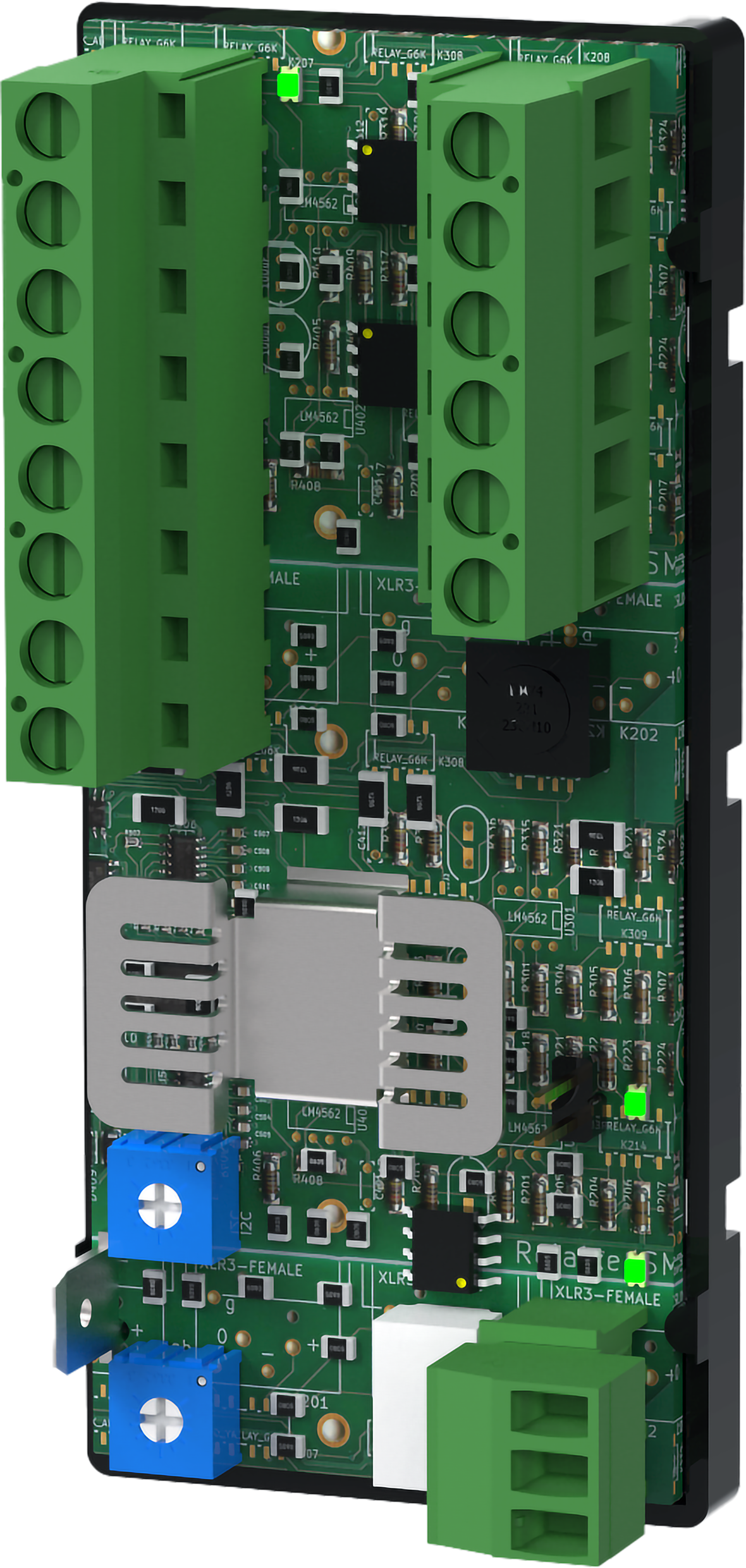
Voltage converter 24-12V 2A also called Ground fault detector, is an optional board with ground fault indication and with two completely current-limited outputs. The board has controllable outputs, 12 V / 24 V.
Mounting in battery backup
The card is delivered mounted in it's plastic casing, for easy installation.
If the card has come loose, snap it back into the plastic casing.
Mount the card on any card slot in the enclosure, leave space for cables.
Important
Install the board before screwing on wiring or commissioning.
Letter | Explanation | Comment |
|---|---|---|
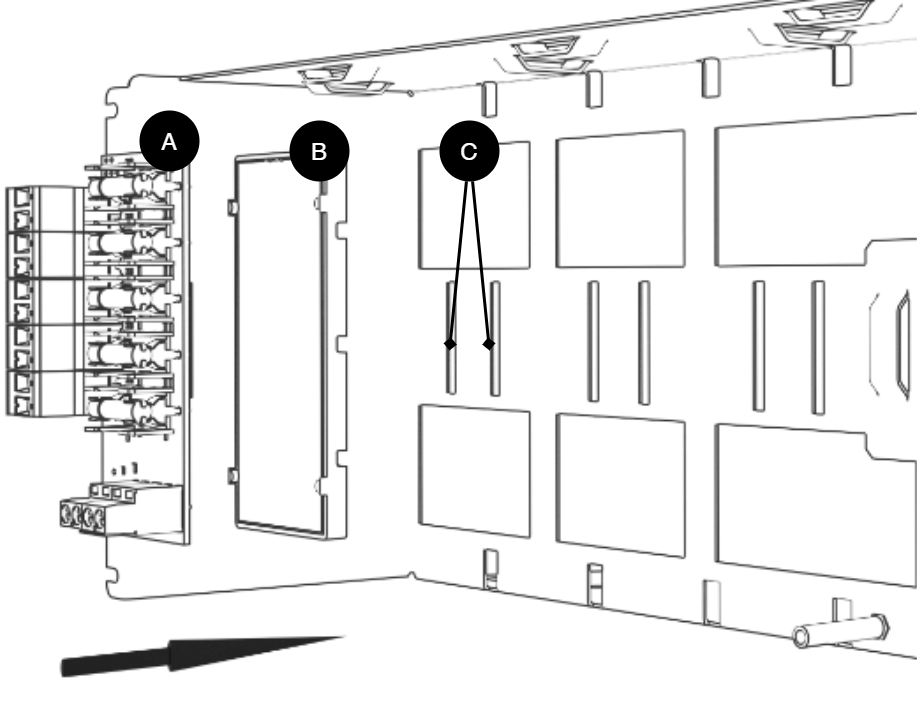
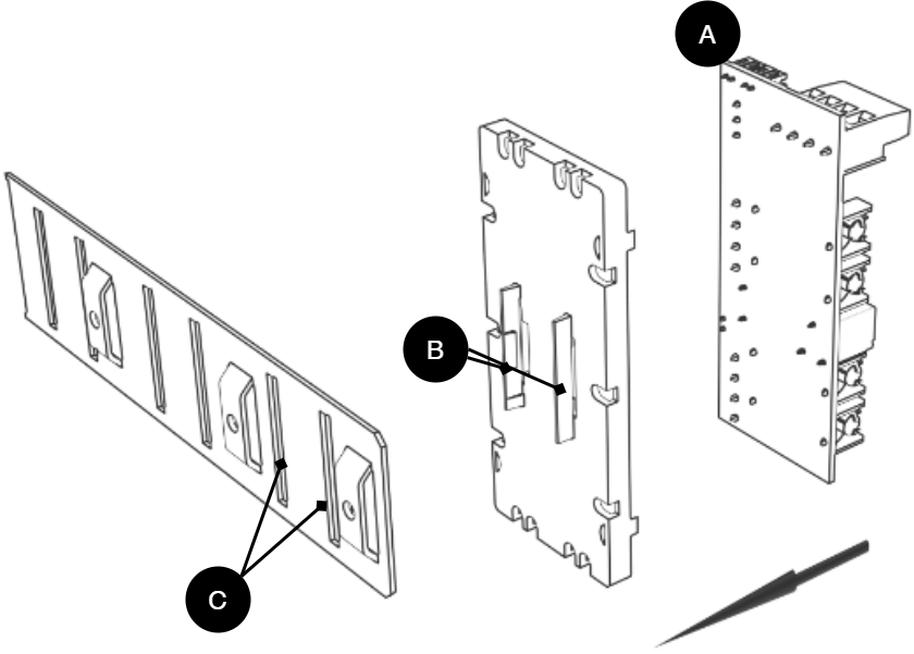
A | Optional card | Optional card comes mounted on plastic housing from factory. Has it come loose? Snap it back on before mounting the card. |
B | Plastic casing | The plastic casing has hooks for attaching slots in the plate. |
C | Place for plastic casing | Slits in sheet metal to snap the plastic bracket. |
PCB description
No | Explanation | No | Explanation |
|---|---|---|---|
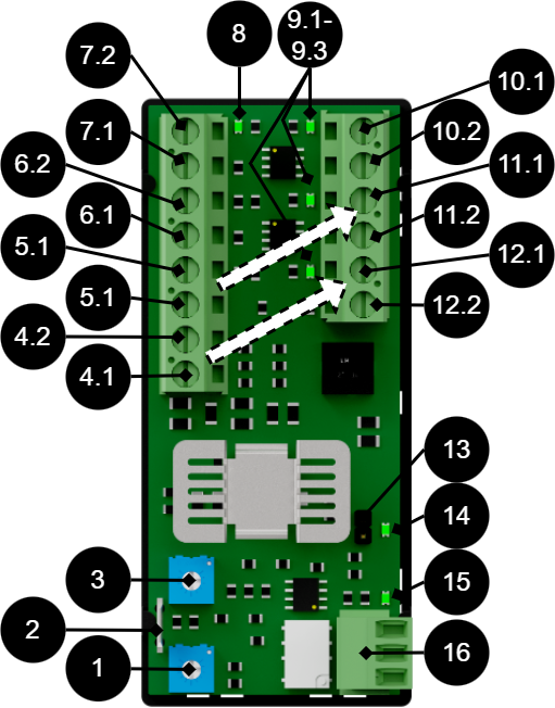
1 | Ground misalignment -. | ||
2 | Ground pin. | ||
3 | Ground fault adjustment +. | ||
4.1 | Controllable output, + high (24 V). Control load output: | 12.2 | Load output + |
4.2 | Controllable output, - low (0 V). Control load output: | 12.1 | load output - |
5.1 | Controllable output, + high (24 V). Control load output: | 11.2 | Load output + |
5.1 | Controllable output, - low (0 V). Control load output: | 11.2 | load output - |
6.1, 7.1 | 24 V in from motherboard. | ||
6.2, 7.2 | + 24 V in from motherboard. | ||
8 | Indicator diode lights up green when voltage is connected. | ||
9.1-9.3 | Indicator diode lights up green when there is voltage out. | ||
10.1 | Cargo access - (not controllable). | ||
10.2 | Load access + (not controllable). | ||
13 | Jumper for 12 V or 24 V control of the board. Unbridged = 12 V, bridged = 24 V. | ||
14, 15 | Indicator diode lights up yellow in the event of an ground fault. | ||
16 | Alarm output, NC/CO/NO |
Connecting the board to the motherboard in battery backup
Load and alarm | PRO1 - Motherboard in battery backup | Voltage Converter 24V-12V 2A | Comment |
|---|---|---|---|
Alarm | J15 | J8 | Use the supplied cable |
Load | Load output 1 | IN +/- | Use cable, max 2.5 mm2, not included. |
Load and alarm | PRO2 v3 - Motherboard in battery backup | Voltage Converter 24V-12V 2A | Comment |
|---|---|---|---|
Alarm | J7 | J8 | Use the supplied cable |
Load | Load output 1 | IN +/- | Use cable, max 2.5 mm2, not included. |
Load and alarm | PRO3 - Motherboard in battery backup | Voltage Converter 24V-12V 2A | Comment |
|---|---|---|---|
Alarm | J10 | J8 | Use the supplied cable |
Load | Load output 1 | IN +/- | Use cable, max 2.5 mm2, not included. |
Connection of load on the card
Caution
Connect load before commissioning battery backup.
Connect load wiring. LOAD (10.1,10.2) is prioritized load output. LOAD 1 (11.1, 11.2) and LOAD 2 (12.1, 12.2) are controllable outputs.
Alarm is connected to 16 - NC/CO/NO
If the card is to be used for ground fault monitoring: Connect ground cable to ground pin on the board and ground in battery backup. If the card is not to be used for earth fault monitoring, this step can be skipped.
Enable battery backup. See manual for battery backup.
Caution
Maximum load is 2 A per load output, and the card's total load must not exceed 2.5 A.
Ground fault monitoring
Earth fault monitoring takes place via the supply from the battery backup into the card (1 or 3). This means that battery backup is earth-fault monitored if the board is powered.
Turn potentiometer, (1, 3), clockwise to reduce earth fault indication sensitivity.
14 and 15 light up yellow in the event of an earth fault. If the potentiometer is adjusted, the indicator diodes will turn off (unless there is an earth fault).
Technical data
Article number, voltage converter | A-VC002402A01LM01 |
Article number, ground fault detector | A-OT0024EA01LM01 |
Product description | Voltage converter 24V to 12V/2A with 2 controllable outputs and ground fault indication. |
Measure | 85 x 37 mm |
Own consumption | 22mA |
Entrances | Two entrances. (For alternative power supply when changing local units. In order not to interrupt the load voltage.) A terminal can be used as a bridge to the next optional card, (only if the battery backup has room for two cards). |
Voltage in | 24 V |
Voltage out | 12 V or 24 V. |
Outputs | 3 prioritized current-limited load outputs. Two outputs are controllable. |
Fuses | Outputs are current limited, which is why load fuses are not needed. |
Max load | 2 A per output and a total of 2.5 A. |
Alarm output | NO, CO, NC |
Alarm | Sum-alarm in the event of an ground fault. Alarm on potential-free relay contact. |
Indication: | One indicator diode per load output +/-. Steady green light = normal operation, Red LED = alarm error. |
Ground fault adjustment | +/- |
About translation of this document
User manual and other documents are in the original language in Swedish. Other languages are machine translated and not reviewed, errors may occur.
Address and contact details
Milleteknik AB |
Ögärdesvägen 8 B |
S-433 30 Partille |
Sweden |
+46 31 340 02 30 |
info@milleteknik.se |
www.milleteknik.com |