
Technical specifications: Tamper switch
T-Tamperswitch is an accessory for battery backups which is a microswitch whic,h when connected to the motherboard, gives an alarm for tampering.
T-Tamperswitch can also be connected to external alarms, this is done in the devices that do not support tamper alarms on motherboards.
Installation of tamper switch in M
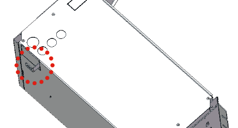
Tamper switch in the cabinet of size M has its place on the right, in front of the cable entry.
IN there is no connection for tamper contact on circuit boards, so alarms from tamper switches must be connected externally.
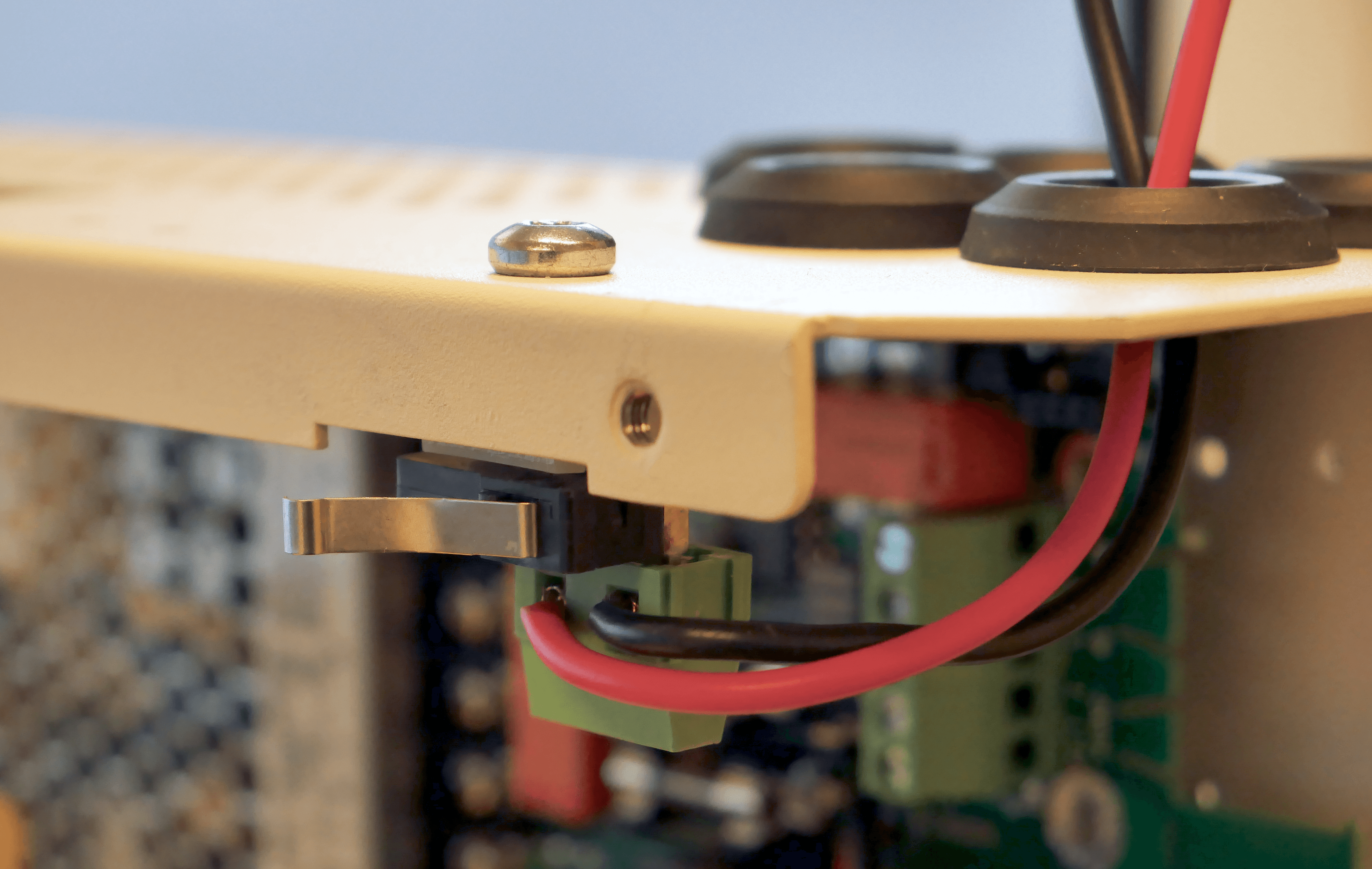
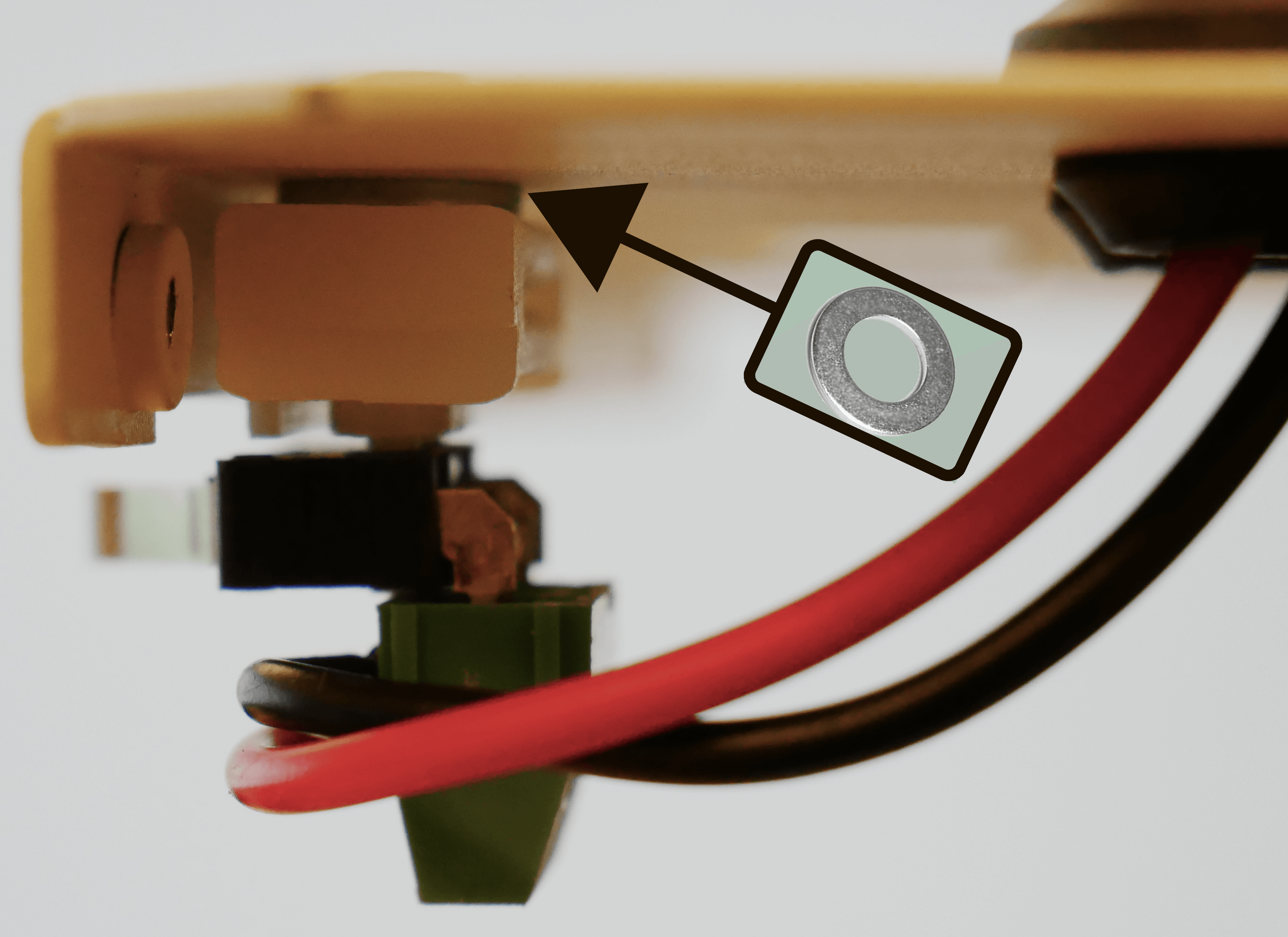
Screw tamper switch in the roof of the cabinet.
There should be a washer between the white piece of plastic and the ceiling on the inside of the cabinet.
(If the washer is on the top, it is not possible to close the lid.)
Connect cables, tamper connector has no connection on circuit board.
Tamper switch and alarm class 3/4 according to SSF1014
Tamper switch must be attached to the wall to comply with alarm class 3/4 according to SSF1014.
The tamper switch must be connected to the system board.
If the distance is long from the wall when mounting in a rack, for example, a spaccer is needed. It is the installer's responsibility to install the appropriate spacer. The tamper switch in the cabinet must end when the cabinet door is closed. If the alarm goes off ("tamper alarm" / alarm to the control panel), the lever may need to be adjusted.
Tolerance levels for tamper contact: Alarm must be triggered when: Opening the cabinet door; > 1 mm. Breaking unit from wall:> 2.5 mm.
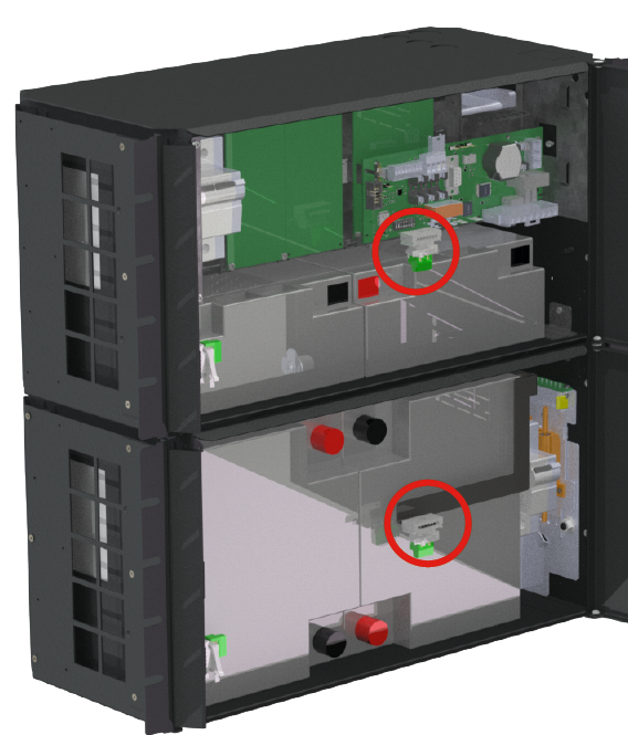
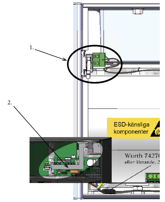
The picture shows location in battery backup and battery box.
Installation of tamper switch in FLX S
Tamper switch placements
The T-Tamperswitch must be in one of two placements:
To alarm when the door is opened, then the T-Tamperswitch placed in the cabinet above the lock.
In the wall to give an alarm in the event of breakage of the entire enclosure T-tamperswitch must be mounted in the wall to meet the alarm class according to SSF. Note that sheet metal angle may differ from actually delivered.
Installation of tamper switch in FLX M
Tamper switch placements
The T-Tamperswitch must be in one of two placements:
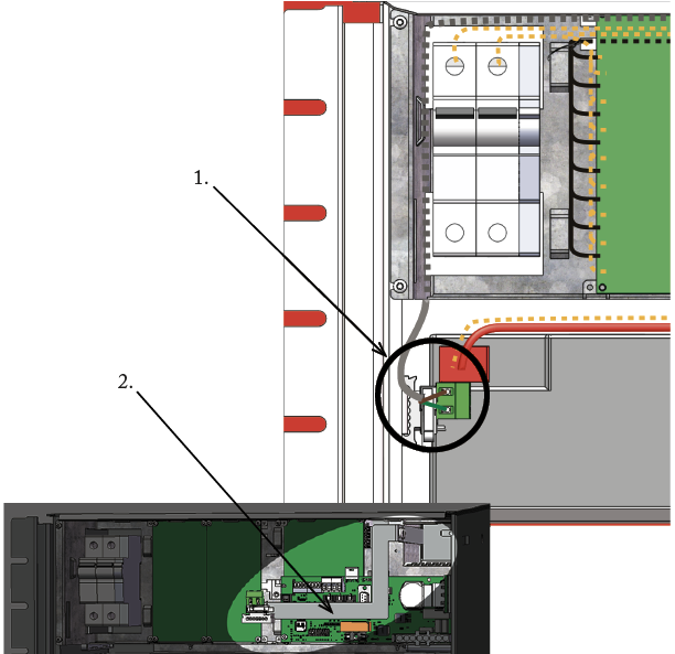
To alarm when the door is opened, then the T-Tamperswitch placed in the cabinet above the lock.
In the wall to give an alarm in the event of breakage of the entire enclosure T-tamperswitch must be mounted in the wall to meet the alarm class according to SSF. Note that sheet metal angle may differ from actually delivered.
Installation of tamper switch in FLX L
Tamper switch placements
The T-Tamperswitch must be in one of two placements:
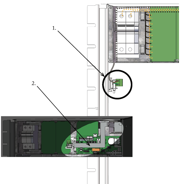
To alarm when the door is opened, then the T-Tamperswitch placed in the cabinet above the lock.
In the wall to give an alarm in the event of breakage of the entire enclosure T-tamperswitch must be mounted in the wall to meet the alarm class according to SSF. Note that sheet metal angle may differ from actually delivered.
Connection of tamper switch on PRO1
The battery backup should not be connected to mains when connecting.
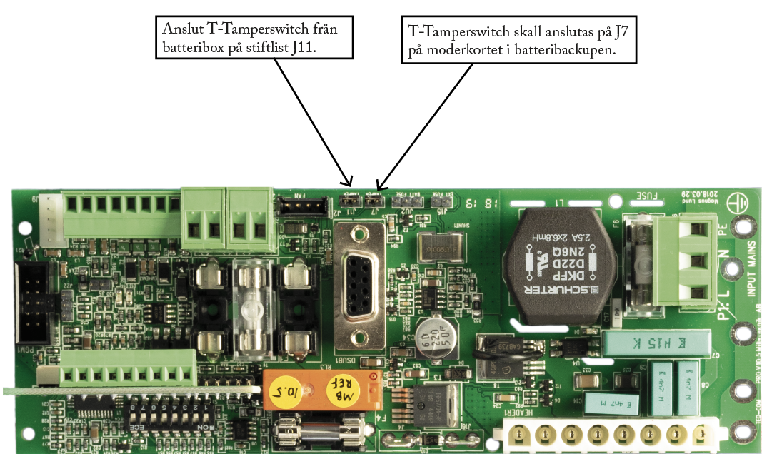
Connector from T-Tamperswitch must be connected to J7 on the motherboard in the battery backup.
The connector from the T-Tamperswitch in the battery box must be connected to J11 on the motherboard in the battery backup.
Alarm from tamper
When the T-Tamperswitch is correctly installed, an alarm must be given on the cabinet door (Slow green flashing) to the Sabotage (tamper) battery backup.
If the battery backup is connected to an alarm-station then alarm for sabotage will be given when the micro switch connection is broken.
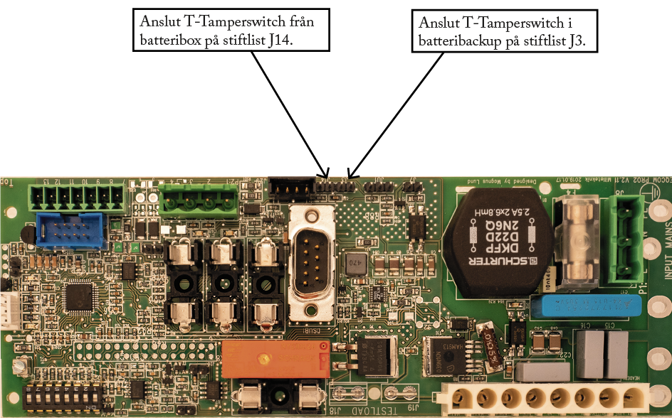
Connection of tamper switch on PRO2
The battery backup should not be connected to mains when connecting.
Connector from T-Tamperswitch must be connected to J3 on the motherboard in the battery backup.
The connector from the T-Tamperswitch in the battery box must be connected to J14 on the motherboard in the battery backup.
Alarm from tamper
When the T-Tamperswitch is correctly installed, an alarm must be given on the cabinet door (Slow green flashing) to the Sabotage (tamper) battery backup.
If the battery backup is connected to an alarm-station then alarm for sabotage will be given when the micro switch connection is broken.
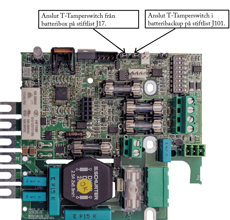
Connection of tamper switch on PRO3
The battery backup should not be connected to mains when connecting.
Connector from T-Tamperswitch must be connected to J101 on the motherboard in the battery backup.
The connector from the T-Tamperswitch in the battery box must be connected to J7 on the motherboard in the battery backup.
Alarm from tamper
When the T-Tamperswitch is correctly installed, an alarm must be given on the cabinet door (Slow green flashing) to the Sabotage (tamper) battery backup.
If the battery backup is connected to an alarm-station then alarm for sabotage will be given when the micro switch connection is broken.
Adjustment of tamper switch
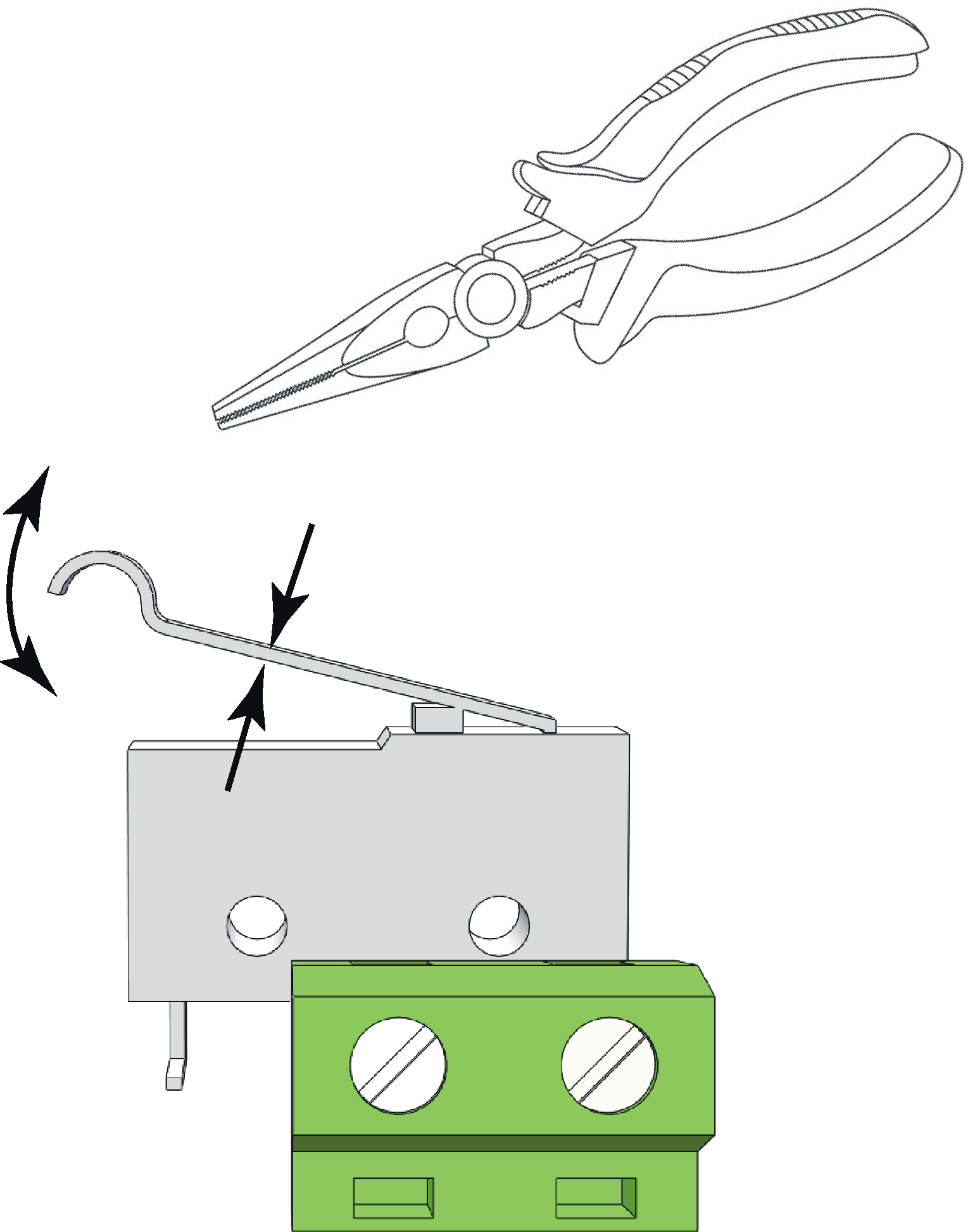 |
The tamper switch lever must be in the closed position when the cabinet door is closed. If the alarm goes off ("tamper alarm"), the lever may needs to be adjusted.
The lever is adjusted by the following steps:
Pinch with pliers in the middle of the lever.
Carefully adjust the lever in the desired direction (up / down).
Check by closing the door. A click is heard when the contact is closed.
Notice
Tamper switch will not give an alarm when closed and locked the door.
Connection of tamper devices that do not have a communcation connection
If there is no connection on the circuit board, as in , alarms from tamper switches must be connected to an external alarm.
Technical data: Tamper switch
Name | T-Tamperswitch |
Article number | A-0000000SAB01 |
Type | Microswitch |
Voltage | 12 V / 24 V |
About translation of this document
User manual and other documents are in the original language in Swedish. Other languages are machine translated and not reviewed, errors may occur.