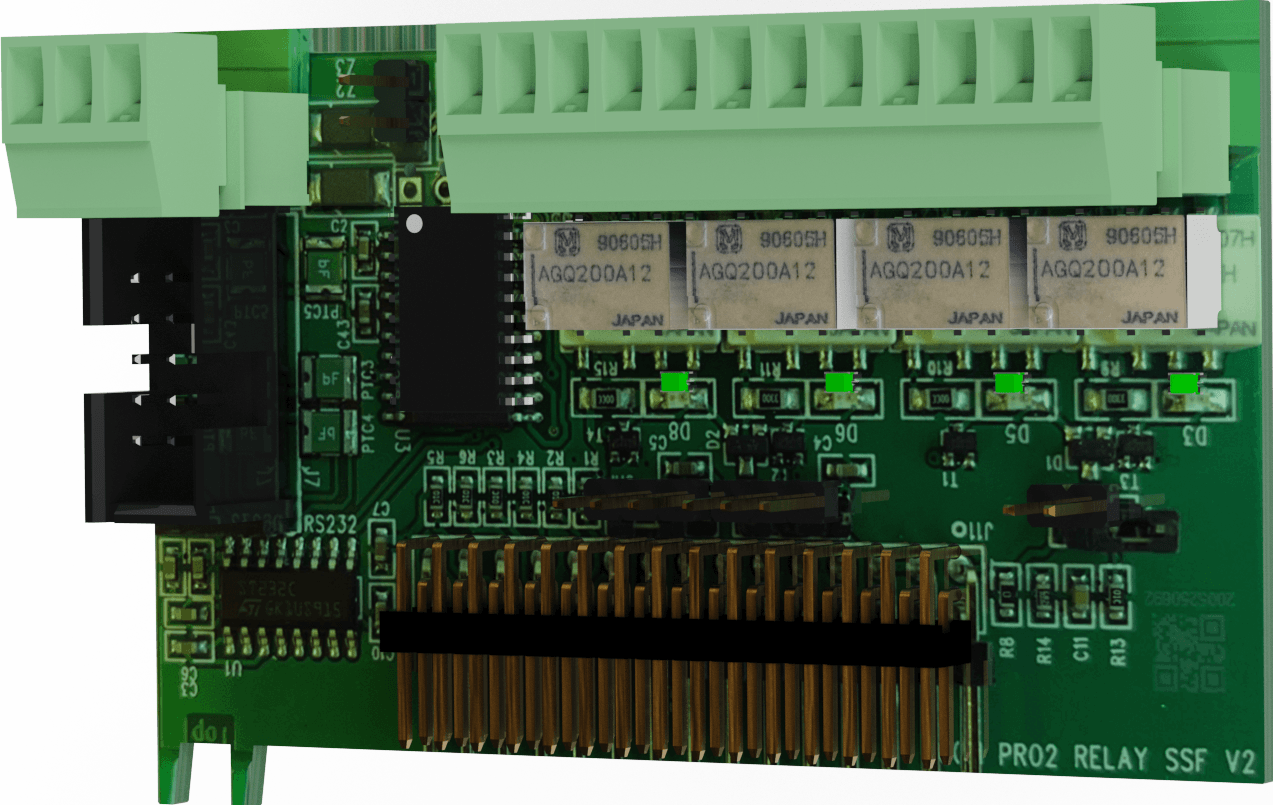
Technical specifications Relay Card NOVA Series (15A and 25A-PRO2V3)
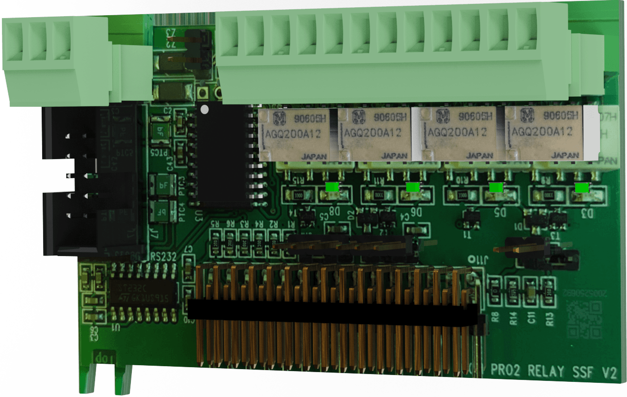
With 4 pcs. relay outputs for systems supplied with PRO2 v3 motherboards.
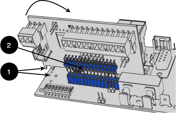
Assembly of Relay Card NOVA Series (15A and 25A-PRO2V3) Motherboard-PRO2 v3
No | Explanation |
|---|---|
1 | Insert the tags into the holes first. Then fold the card down towards the stiffener. |
2 | Pin and pin strip for connection. |
Alarm card for PRO2
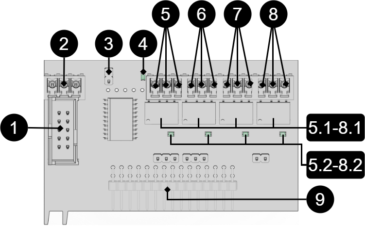
Relay card - description, connections and alarm outputs.
All fault arm relays must be in the drawn state. Check that there is a gap between CO and NC. Put the measuring instrument on continuity measurement and test closure. This should then indicate a short circuit.
All relay outputs are normally live and give an alarm in the event of no voltage.
Important
There is normally a 10 second delay in alarm reset. The software on the main board must be configured for a different time period.
 |
No . | Relay (Terminal no.) | The relay is normally energized. | Alarm type / explanation |
|---|---|---|---|
1 | J7 | - | Connection for RS-232 cable. |
2 | P4:1 | - | RS-232: TxD, data OUT from motherboard. |
P4:2 | - | RS-232: RxD, data IN to motherboard. | |
P4:3 | - | RS-232: Ground, do not connect ground to another terminal. | |
3 | J6 | - | Reset jumper. |
4 | D7 | - | Indicator diode, flashes green during normal operation. |
5,5.1, 5.2 | P5:1-3 | NO, COM, NC | Tamper alarm, (optional for EN54). 5.1 Relay. 5.2 LED, lights up green when relay is energized. |
6, 6.1, 6.2 | P5:4-6 | NO, COM, NC | Alarm for: Low system voltage. 6.1 Relay. 6.2 LED, lights up green when relay is energized. |
7, 7.1, 7.2 | P5:7-9 | NO, COM, NC | Alarm for: Fuse failure, charger failure overvoltage, charger failure undervoltage, cell failure/not connected battery, low battery voltage in case of mains failure and aged battery. 7.1 Relay. 7.2 LED, lights up green when relay is energized. |
8, 8.1, 8.2 | P5:10-12 | NO, COM, NC | Power failure alarm. 8.1 Relay. 8.2 LED, lights up green when relay is energized. |
9 | J11 | - | Connection to motherboard. |
Via communication on PRO1 card: All alarms and alarms for: Fan fault, overtemperature, subtemperature, short battery life left, overcurrent 100% of minute average, overcurrent 80% daily average and overcurrent 175% second average. | |||
Technical data, alarm cards for PRO 2 and PRO2 V3
Info | Explanation |
|---|---|
Card name: | PRO2 larmkort |
Version: | 2.0 |
Product description | Alarm card for PRO2 and PRO2 V3 with alarm on alternating relay. All relays are normally energized and give an alarm in a voltage-free position. |
self-consumption | 40 mA |
Alarm overview in alphabetical order | Relay 1 * / Alarm output 1 | Relay 2 * / Alarm output 2 | Relay 3 * / Alarm output 3 | Relay 4 * / Alarm output 4 | Communication (P1: 1-12) | Indicator LED on motherboard and LED on door. |
|---|---|---|---|---|---|---|
Network outages | X | - | - | - | X | X |
Fuse fault | - | X | - | - | X | X |
Sabotage switch | - | - | - | X | X | X |
Fan fault | - | - | - | - | X | - |
Charger fault, overvoltage | - | X | - | - | X | X |
Charger fault, undervoltage | - | X | - | - | X | X |
Cell fault or unconnected battery | - | X | - | - | X | X |
Low system voltage. ** | - | - | X | - | X | X |
Low battery voltage (<24.0 V DC) or power failure | - | X | - | - | X | X |
Overtemperature | - | - | - | - | X | - |
Undertemperature | - | - | - | - | X | - |
Undertemperature | - | - | - | - | X | - |
Short battery life left | - | - | - | - | X | - |
Aged battery | - | X | - | - | X | X |
Overcurrent 100%, minute average | - | - | - | - | X | - |
Overcurrent 80%, daily average | - | - | - | - | X | - |
Overcurrent 175%, second average | - | - | - | - | X | - |
* Alarm on potential-free relay contact.
** System voltage in mains operation is below 24.0 V.
350-232
About translation of this document
User manual and other documents are in the original language in Swedish. Other languages are machine translated and not reviewed, errors may occur.
Address and contact details
Milleteknik AB |
Ögärdesvägen 8 B |
S-433 30 Partille |
+46 31 340 02 30 |
www.milleteknik.com |