Technical specifications: Relay Card NOVA Series (PRO3)
With 4 pcs. relay outputs for systems supplied with PRO3 motherboards.
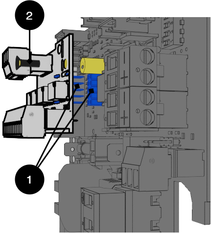
Installation of Relay card NOVA Series on motherboard-PRO3
 |
No | Explanation |
|---|---|
1 | Pin and pin strip for connection. |
2 | Screw to secure mounting. |
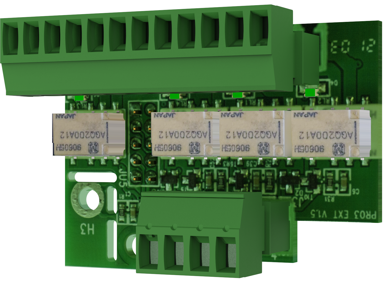
Card Description - Relay Card NOVA Series (PRO3)
Relay card - description, connections and alarm outputs.
All fault arm relays must be in the drawn state. Check that there is a gap between CO and NC. Put the measuring instrument on continuity measurement and test closure. This should then indicate a short circuit.
All relay outputs are normally live and give an alarm in the event of no voltage.
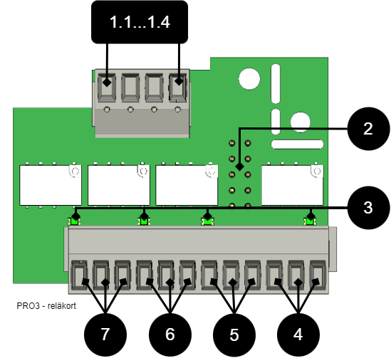 |
No . | Terminal no. | The relay is normally energized. | Alarm type / explanation |
|---|---|---|---|
1.1...1.4 | P4:1 | - | GND, protective earth |
P4:2 | - | RX | |
P4:3 | - | TX | |
P4:4 | - | +5V | |
2 | JU5 | - | Connection to motherboard. |
3 | D2-D6 | - | Indicator diode, lit green when OK. |
4 | P5:10-12 | NC, COM, NO | Alarm from tamper switch, (optional for NEO and EN54). |
5 | P5:7-9 | NC, COM, NO | Low system voltage. |
6 | P5:4-6 | NC, COM, NO | Alarm for fuse failure, charger failure overvoltage, charger failure undervoltage, battery not connected, low battery voltage in case of mains failure and aged battery*. *NOVA only. |
7 | P5:1-3 | NC, COM, NO | Mains failure alarm. |
Technical data, alarm card for PRO 3 / NEO3
Info | Explanation |
|---|---|
Card name: | PRO 3 |
Version: | 1.2 |
Product description | Motherboard in battery backup with advanced functions and communication to superior systems. |
Recommended environment | Indoors, class 1. Ambient temperature: + 5 ° C - 40 ° C. |
Protection class | IPX0 |
Recommended installation | NOVA Series (only 5 A and 10 A) |
Input voltage | 13.6 VDC, 27.3 VDC |
Self-consumption | 40 mA |
Alarm via | Alternating relay |
Number of alarm outputs | 4 pcs |
Certified according to | EN 50131-6, SBF 110: 8, SSF1014, Meets alarm class 4, SSF 1014, edition 5 |
Certificate number (SBSC) | 20-117 |
The product meets the requirements according to | CE directive according to: 765/2008, EMC Directive 2014 / 30EU, Emission: EN61000-6-: 2001, EN55022: 1998: -A1: 2000, A2: 2003 Class B, EN61000-3-2: 2001, Immunity: EN61000- 6-2: 2005, EN61000-4-2, -3, 4, -5, -6, -11. SS-EN 50 130-4: 2011 Edition 2 & SSF1014 Alarm class 1-4 (Burglar alarm). |
Producer | Milleteknik AB |
Country of origin | Sweden |
Alarm overview in alphabetical order | Relay 1 * / Alarm output 1 | Relay 2 * / Alarm output 2 | Relay 3 * / Alarm output 3 | Relay 4 * / Alarm output 4 | Communication (P5: 1-9) | Indicator LED on main card and LED on door. |
|---|---|---|---|---|---|---|
Network outages | X | - | - | - | X | X |
Fuse fault | - | X | - | - | X | X |
Sabotage switch | - | - | - | X | X | X |
Fan fault | - | - | - | - | X | - |
Charger fault, overvoltage | - | X | - | - | X | X |
Charger fault, undervoltage | - | X | - | - | X | X |
Cell fault or unconnected battery | - | X | - | - | X | X |
Low system voltage. ** | - | - | X | - | X | X |
Low battery voltage (<24.0 V DC) or power failure | - | X | - | - | X | X |
Overtemperature | - | - | - | - | X | - |
Undertemperature | - | - | - | - | X | - |
Undertemperature | - | - | - | - | X | - |
Short battery life left | - | - | - | - | X | - |
Aged battery | - | X ** | - | - | X ** | X ** |
Overcurrent 100%, minute average | - | - | - | - | X | - |
Overcurrent 80%, daily average | - | - | - | - | X | - |
Overcurrent 175%, second average | - | - | - | - | X | - |
* Alarm on potential-free relay contact. *** Not on NEO battery backups. | ||||||
RS-485 on P4: 1-4 | Explanation |
|---|---|
P4:1 | GND |
P4:2 | RX |
P4:3 | TX |
P4:4 | +5V |
About translation of this document
User manual and other documents are in the original language in Swedish. Other languages are machine translated and not reviewed, errors may occur.
Address and contact details
Milleteknik AB |
Ögärdesvägen 8 B |
S-433 30 Partille |
+46 31 340 02 30 |
www.milleteknik.com |