Name, article number and e-number
Name | Item number | E-number (sv) |
|---|---|---|
8 Output module PTC | A-FU122408OP02 | 52 137 22 |
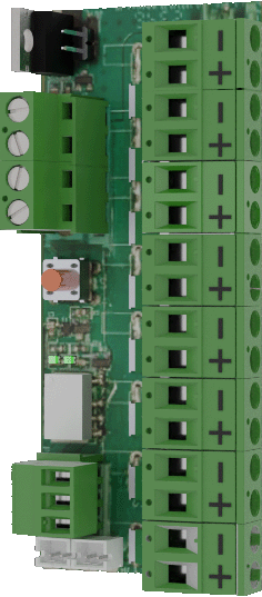
Product image
If
Fuse cards, with sum-alarm, are used to protect electronic circuits from damage due to overcurrent or short circuit.
Important
Since the fuses are fixed and cannot be changed, the maximum load per output must not exceed 2.7 A. The maximum load for the entire board is 10 A.
What is a PTC fuse?
A PTC fuse, where "PTC" stands for "Positive Temperature Coefficient," is a type of thermal fuse or overcurrent protection device. These fuses are used to protect electrical circuits from overcurrent and short circuits.
The fuse works by changing its resistance characteristic when it gets too hot due to high current. When the current becomes too large, the temperature in the fuse increases, causing it to become less conductive and restrict the flow of current. When the temperature in the fuse goes down, the fuse returns to its normal state and allows current to pass as usual.
Mounting in battery backup
The card is delivered mounted in it's plastic casing, for easy installation.
If the card has come loose, snap it back into the plastic casing.
Mount the card on any card slot in the enclosure, leave space for cables.
Important
Install the board before screwing on wiring or commissioning.
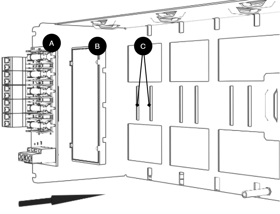
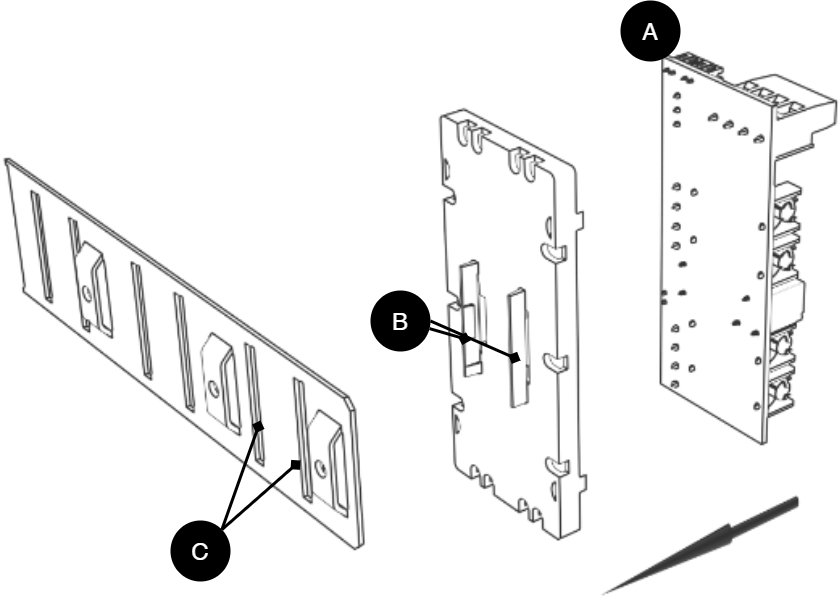
Letter | Explanation | Comment |
|---|---|---|
A | Optional card | Optional card comes mounted on plastic housing from factory. Has it come loose? Snap it back on before mounting the card. |
B | Plastic casing | The plastic casing has hooks for attaching slots in the plate. |
C | Place for plastic casing | Slits in sheet metal to snap the plastic bracket. |
Short description
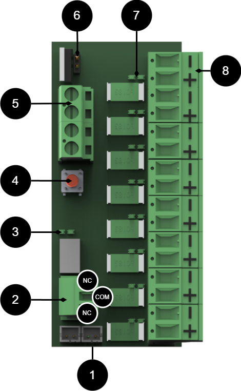
No | On circuit board | Explanation | |||||||||||||||||||||||||||||||||||||||||||||||
|---|---|---|---|---|---|---|---|---|---|---|---|---|---|---|---|---|---|---|---|---|---|---|---|---|---|---|---|---|---|---|---|---|---|---|---|---|---|---|---|---|---|---|---|---|---|---|---|---|---|
1 | J14, J15 | Connection to alarm on motherboard. Bridging connection for alarms from another card. | |||||||||||||||||||||||||||||||||||||||||||||||
2 | P3:1-3 | Alarm output, NC/COM/NO. | |||||||||||||||||||||||||||||||||||||||||||||||
3 | D19, D16 | Indicator diode. Green = ok. RED[a]= alarm. | |||||||||||||||||||||||||||||||||||||||||||||||
4 | S1 | Acknowledgment button for alarms. | |||||||||||||||||||||||||||||||||||||||||||||||
5 | P1 | Incoming voltage from motherboard. | |||||||||||||||||||||||||||||||||||||||||||||||
6 | JU1 | Jumper for switching the card to 12 V. Jumpered = 12 V, Not jumpered = 24 V, factory setting. | |||||||||||||||||||||||||||||||||||||||||||||||
7 | D1-D8 | Indicator diode lights up green when there is voltage at the output. | |||||||||||||||||||||||||||||||||||||||||||||||
8 | P2:1-8 | Load output +/- | |||||||||||||||||||||||||||||||||||||||||||||||
[a] Lights up red until the alarm is acknowledged. | |||||||||||||||||||||||||||||||||||||||||||||||||
Connect 8 Output module PTC to motherboard: CEO3 v 2.1
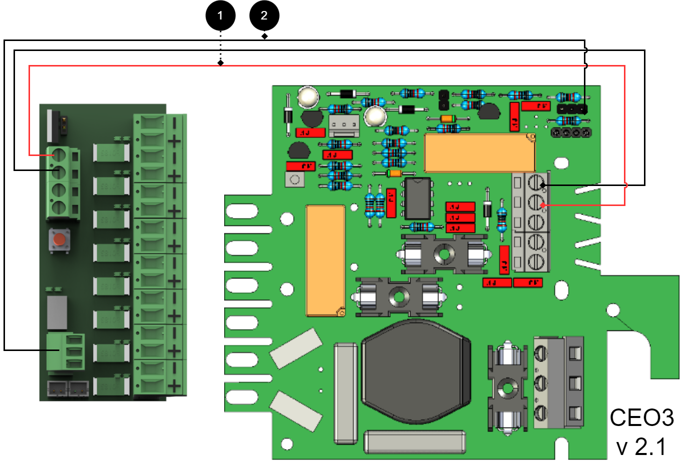
+ and - from load on motherboard are connected to + and - on the option board.
Communication is connected between terminals as the solid line shows.
Connecting the power supply
Connect power (24 V) from the battery backup's load output to the card's 24 V input.
Connection of load
Connect load wiring to P2:1-8 on 8 Output module PTC.
Warning
Maximum load is 1.85 A per load output and the card's total load must not exceed 10 A.
No | Connections | 8 Outoput module PTC | Motherboard |
|---|---|---|---|
1 | Power supply connection | P1:1-4 | Optional load output. |
2 | Alarm output: connected between NO and COM | P3:1-3 | JU3 Connects between the middle pin and an outer pin. |
- | Bridging alarms to the card is not possible as the card has no alarm input. | - | - |
Connect 8 Output module PTC to motherboard: CEO 3 v5
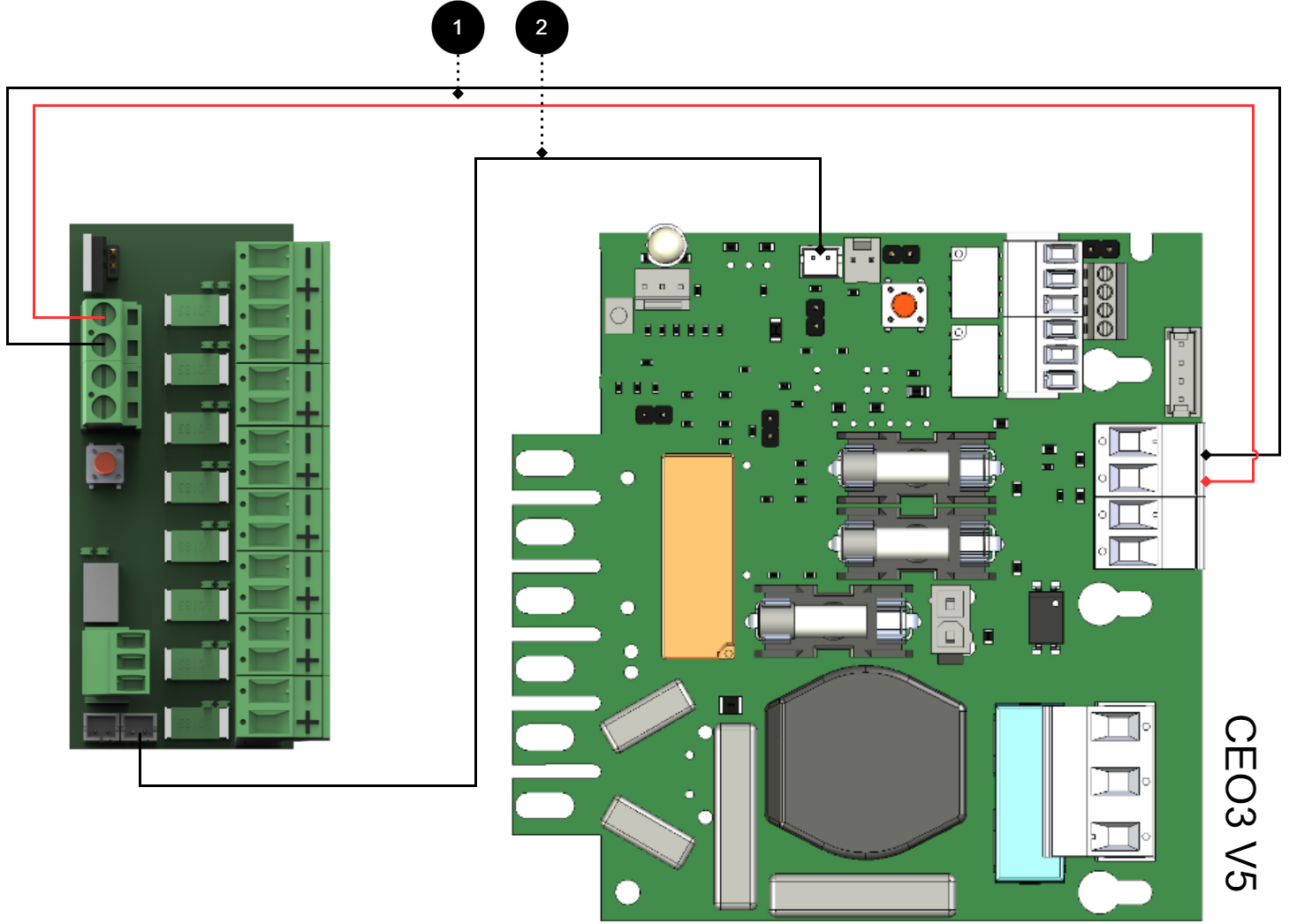
+ and - from load on motherboard are connected to + and - on the option board.
Communication is connected between terminals as the solid line shows.
Connecting the power supply
Connect power (24 V) from the battery backup's load output to the card's 24 V input.
Connection of load
Connect load wiring to P2:1-8 on fuse module for priority load.
Warning
Maximum load is 1.85 A per load output and the card's total load must not exceed 10 A.
No | Connections | 8 Outoput module PTC | Motherboard |
|---|---|---|---|
1 | Power supply connection: | P1:1-4 | Optional load output |
2 | Bridging alarm to motherboard: Bridging of alarms to additional option cards | J14 J15 | J27 |
Connect 8 Output module PTC to motherboard: NEO3
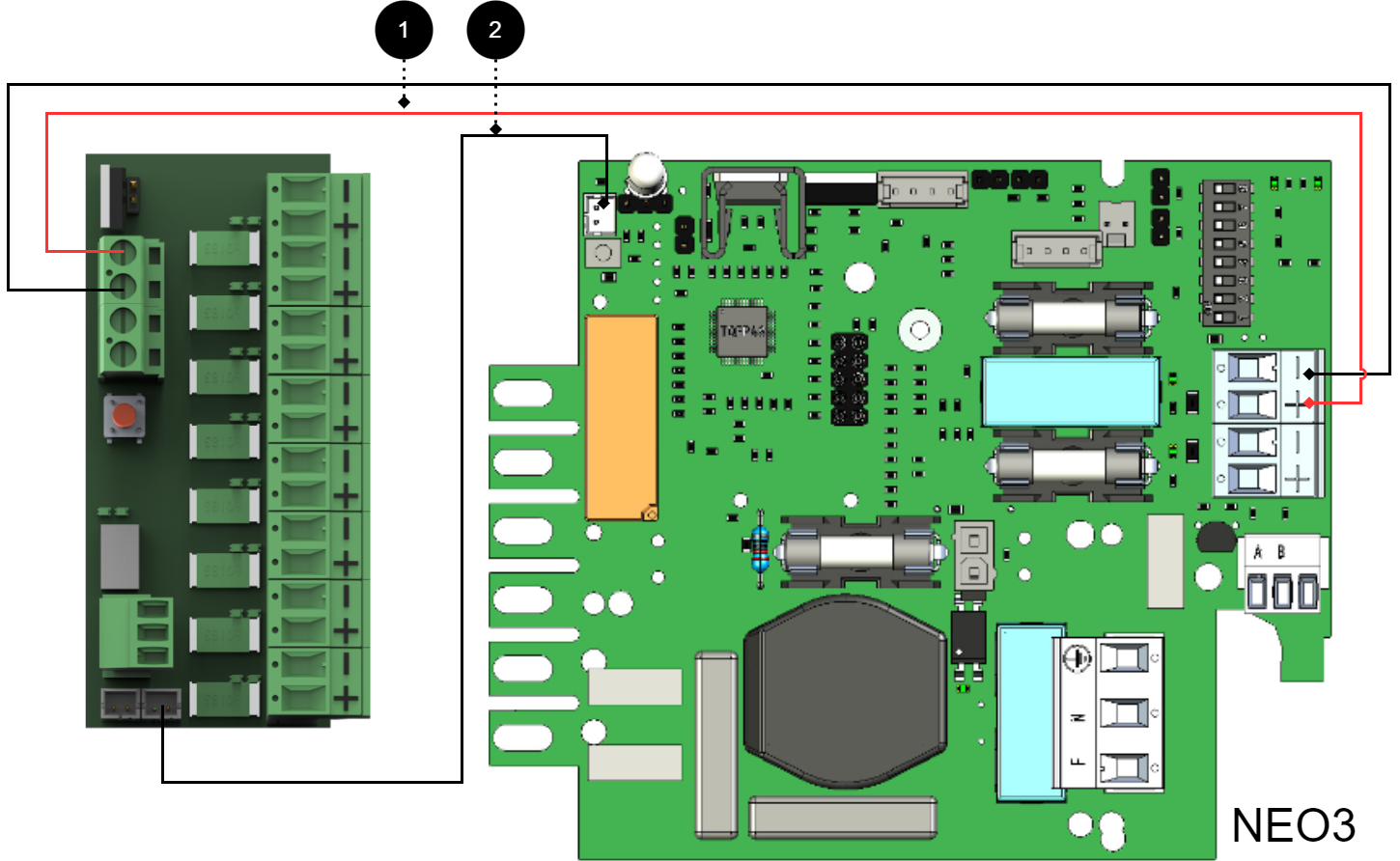
+ and - from load on motherboard are connected to + and - on the option board.
Communication is connected between terminals as the solid line shows.
Connecting the power supply
Connect power (24 V) from the battery backup's load output to the card's 24 V input.
Connection of load
Connect load wiring to P2:1-8 on 8 Output module PTC.
Warning
Maximum load is 1.85 A per load output and the card's total load must not exceed 10 A.
No | Connections | 8 Outoput module PTC | Motherboard |
|---|---|---|---|
1 | Power supply connection: | P1:1-4 | Optional load output. |
2 | Bridging alarm to motherboard: Bridging of alarms to/from additional option cards | J14 J15 | J5 |
Connect 8 Output module PTC to motherboard: PRO1, 5 A - 10 A
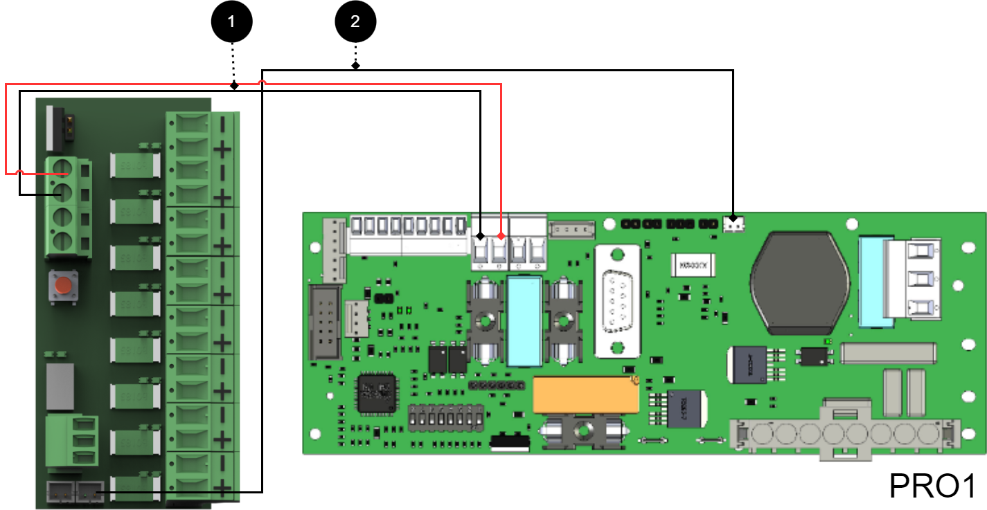
+ and - from load on motherboard are connected to + and - on the option board.
Communication is connected between terminals as the solid line shows.
Connecting the power supply
Connect power (24 V) from the battery backup's load output to the card's 24 V input.
Connection of load
Connect load wiring to P2:1-8 on 8 Output module PTC.
Warning
Maximum load is 1.85 A per load output and the card's total load must not exceed 10 A.
No | Connections | 8 Output control module | Motherboard |
|---|---|---|---|
1 | Power supply connection: | P1:1-4 | Optional load output |
2 | Bridging alarm to motherboard: Bridging alarms to/from additional option cards: | J14 J15 | J13 - |
Connect 8 Output module PTC to motherboard: PRO1, 15 A - 25 A
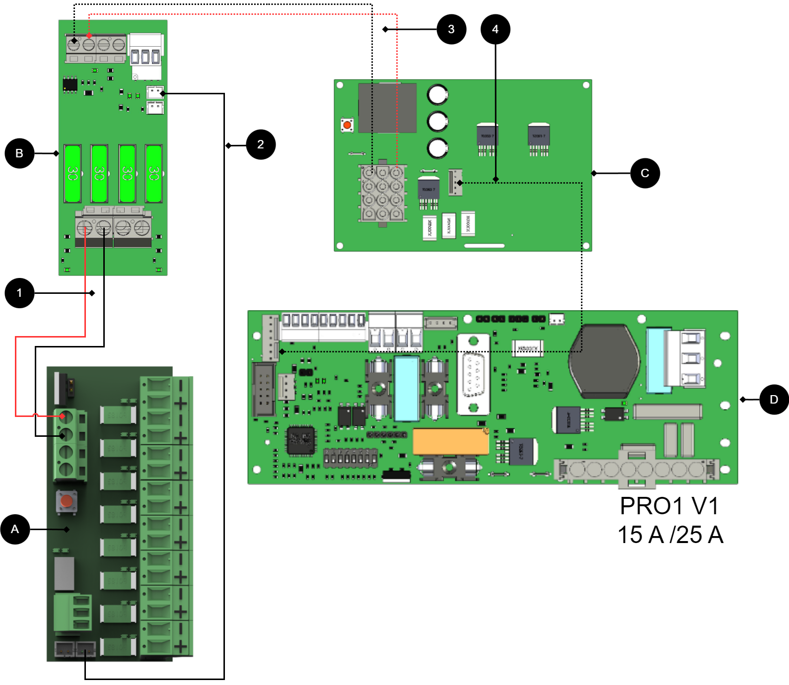
+ and - from load on motherboard are connected to + and - on the option board.
Communication is connected between terminals as the solid line shows.
Connecting the power supply
Connect power (24 V) from the battery backup's load output to the card's 24 V input.
Connection of load
Connect load wiring to P2:1-8 on 8 Output module PTC.
Warning
Maximum load is 1.85 A per load output and the card's total load must not exceed 10 A.
No/letter | On circuit board (A) | Explanation |
|---|---|---|
A | 8 Output modules | Optional card. |
B | 2 Output module | Card for connection of load and power supply to 8 Outoput module PTC. |
C | Effect card | Available in 15 A and 25 A units. |
D | PRO1 | Motherboard in battery backup. |
1 | P1:1-4 | Connect power supply 8 Outoput module PTC from (B). |
2 | J14 | Alarms are connected to load cards. |
3, 4, 5 | - | Internal power supply and communication between cards. |
Connect 8 Output module PTC to motherboard: PRO2 v3, 5 A - 10 A
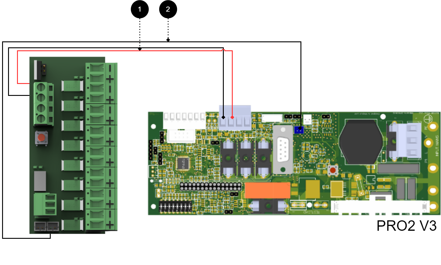
+ and - from load on motherboard are connected to + and - on the option board.
Communication is connected between terminals as the solid line shows.
Connecting the power supply
Connect power (24 V) from the battery backup's load output to the card's 24 V input.
Connection of load
Connect load wiring to P2:1-8 on 8 Output module PTC.
Warning
Maximum load is 1.85 A per load output and the card's total load must not exceed 10 A.
No | Connections | 8 Outoput module PTC | Motherboard |
|---|---|---|---|
1 | Power supply connection: | P1:1-4 | Optional load output. |
2 | Bridging alarm to motherboard: Bridging alarms to additional option cards: | J14 J15 | J1 |
Connect 8 Output module PTC to motherboard: PRO2 v3 15 A - 25 A
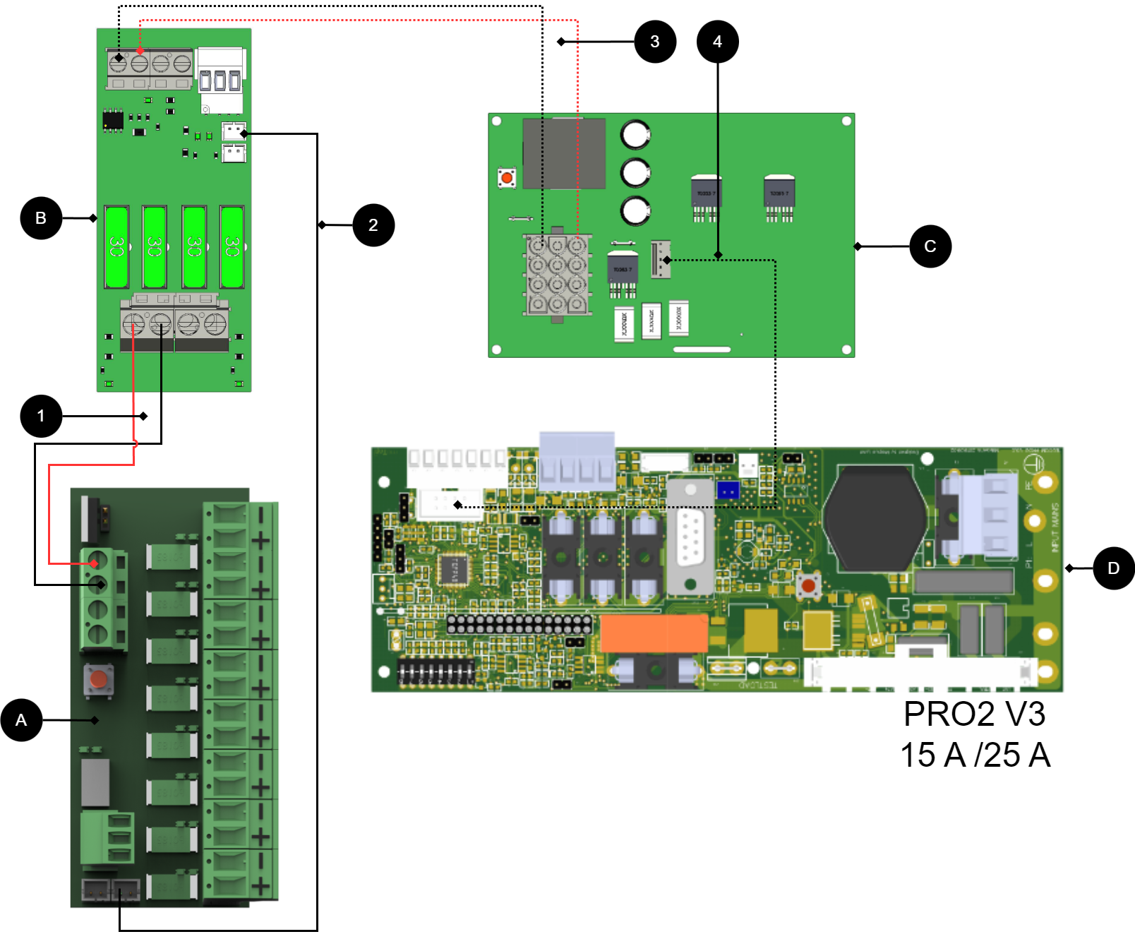
+ and - from load on motherboard are connected to + and - on the option board.
Communication is connected between terminals as the solid line shows.
Connecting the power supply
Connect power (24 V) from the battery backup's load output to the card's 24 V input.
Connection of load
Connect load wiring to P2:1-8 on 8 Output module PTC.
Warning
Maximum load is 1.85 A per load output and the card's total load must not exceed 10 A.
No/letter | On circuit board (A) | Explanation |
|---|---|---|
A | 8 Outoput module PTC | Optional location. |
B | 2 Output module | Card for connection of load and power supply to 8 Outoput module PTC. |
C | Effect card | Available in 15 A and 25 A units. |
D | PRO2 v3 | Motherboard in battery backup. |
1 | P1:1-4 | Disconnect power supply 8 Outoput module PTC (B). |
2 | J14 | Connect alarm to load card. |
3, 4 | - | Internal power supply and communication between cards. |
Connect 8 Output module PTC to motherboard: PRO3 5 A - 10 A
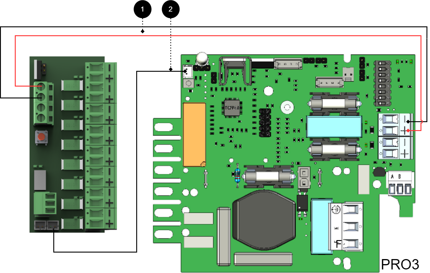
+ and - from load on motherboard are connected to + and - on the option board.
Communication is connected between terminals as the solid line shows.
Connecting the power supply
Connect power (24 V) from the battery backup's load output to the card's 24 V input.
Connection of load
Connect load wiring to P2:1-8 on 8 Output module PTC.
Warning
Maximum load is 1.85 A per load output and the card's total load must not exceed 10 A.
No | Connections | 8 Outoput module PTC | Motherboard |
|---|---|---|---|
1 | Power supply connection: | P3:1-4 | Optional load output. |
2 | Bridging alarm to motherboard: | J14 | J5 |
Connection of another 8 outout module PTC
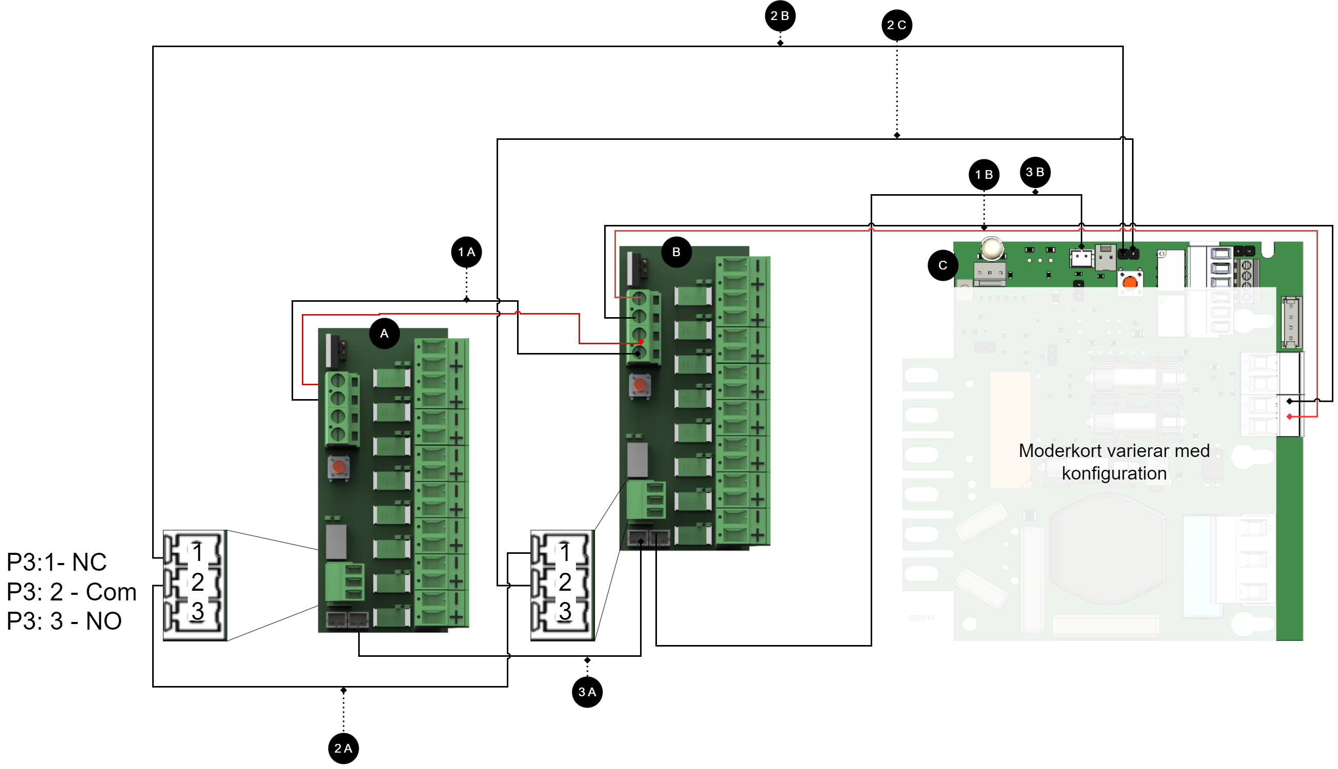
Connecting additional option cards to the motherboard
Note
For alarm connection use 2A and 2B for connection of newer devices (after approx. 2018). For older devices (before approx. 2018) use 3A-3C.
Letter / No | Explanation | On the card |
|---|---|---|
A | 8 Outoput module PTC. | - |
B | 8 Outoput module PTC. | - |
C | Motherboard, may vary with configuration. | - |
1 A | Power supply to 1B from 1A. | P1:1-+2 |
1 B | Power supply to 1B from motherboard. | P1:3-4 |
2 A | Bridging of alarms from card A to card B. | J15 |
2 B | Connection of alarm on C (motherboard) from board A. | See table below. |
2C | Connection of alarm on C (motherboard) from board B. | See table below. |
3 A | Alarm output switches From board A to board B. | J14-J15 |
3 B | Alarm output switches From board A to board B. | J14-J15 |
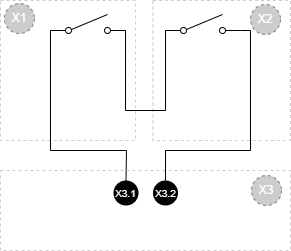
Letter / No | Explanation |
|---|---|
X1 | Optional card 1 |
X2 | Optional card 2 |
X3 | Motherboard |
X3.1 | Connection to motherboard from option board. |
X3.2 | Connection to motherboard from option board. |
Technical data - 8 Output control module
Info | Explanation |
|---|---|
Card name: | 8 Output control module |
Product description | 8 Output control module is a protection module with 10 fully protected outputs, of which seven are prioritized and three are non-prioritized. |
The product fits in | Battery backups with motherboard: PRO1, PRO2, PRO2 V3, PRO3 and NEO3. |
Measure | 120 x 45 mm. |
Own consumption | 65mA |
Output voltage | 24 V |
Fuses | F2A comes with cards. |
Indication | Yes, LED on circuit board |
Info | Value |
|---|---|
Alarm outputs, number | 1 |
Alarm on changing relay? (Yes No) | Yes |
Load outputs, number | 8 |
Voltage on load output | 27.3V DC |
Priority (always voltage) load outputs (Yes/No) | Yes |
Max load, per output | 10 A |
Maximum load, total, (must not be exceeded). | 16 A |
Load output plus (+) fused? (Yes No) | Yes |
Load output minus (-) secured (Yes/No) | No |
Fuses on output | T2A. |
Connection to buzzer? (Yes No) | No |
About translation of this document
User manual and other documents are in the original language in Swedish. Other languages may be machine translated and/or not reviewed, errors may occur.
Address and contact details
Milleteknik AB |
Ögärdesvägen 8 B |
S-433 30 Partille |
Sweden |
+46 31 340 02 30 |
info@milleteknik.se |
www.milleteknik.com |