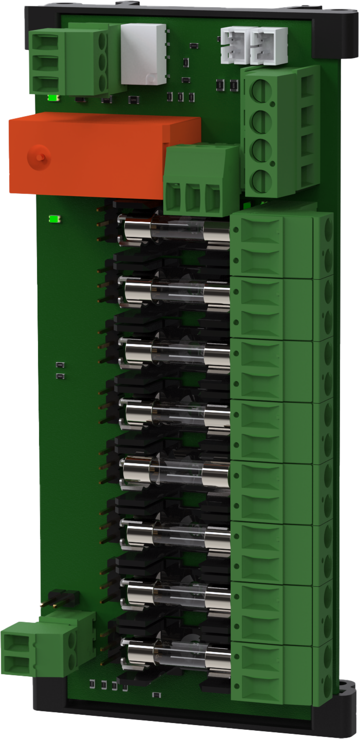
Technical specifications 8 Output control module
8 Output control module is a fuse module with 8 fully fused outputs, The card is mounted on nylon brackets. When ordering, check that the card fits the battery backup card to be installed in.
Installation video
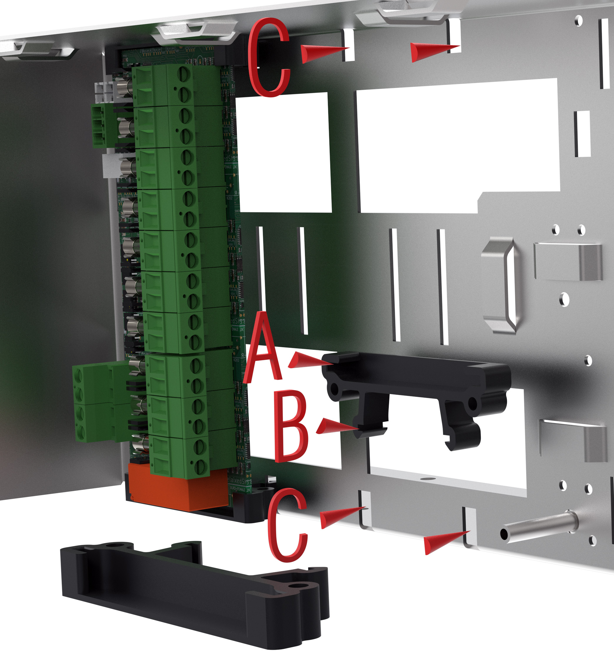
Installation in battery backup
Mount the card in any card slot in the enclosure, leave plenty of room for cables.
Check that the card fits with the device before mounting. Even if the card fits mechanically, it is not guaranteed to be supported electrically. It is the responsibility of the installer that the card is compatible with battery backup.
Note
Install and connect option cards before commissioning battery backup.
Letter | Explanation |
|---|---|
A | The card must sit in the plastic spacers with the connections on the card facing up. |
B | Hooks to attach to the plate (C). |
C | Snap on plastic spacers. |
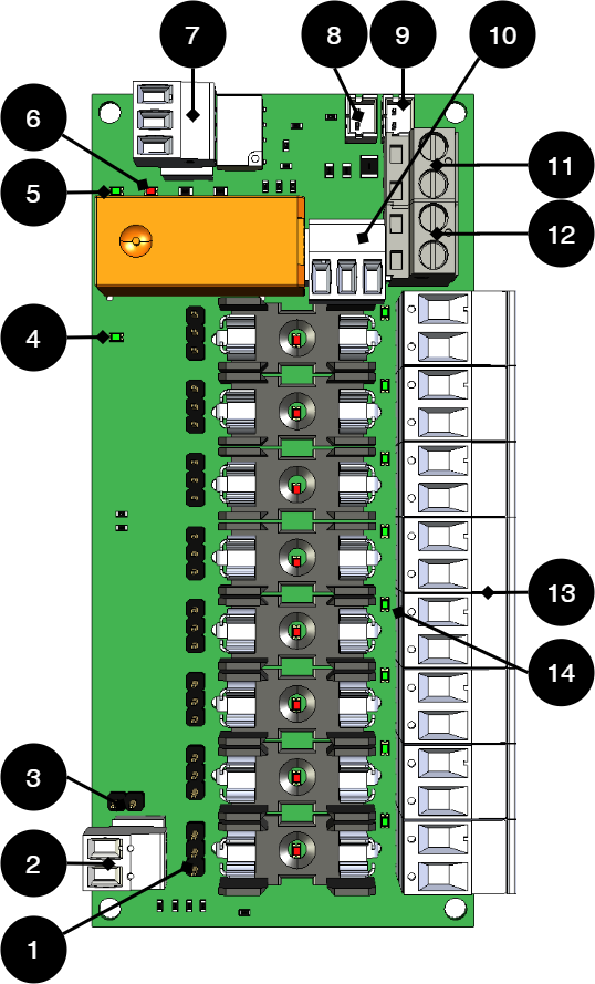
Short description
No | On circuit board | Explanation |
|---|---|---|
1 | JU1-JU8 | The jumper of the pin strip controls which function the output (13) has. Control for function: Jumper between 1-2 = Normal function, always on. Jumper between 2-3=Fire alarm control. See also separate table. |
2 | J9 | Fire alarm circuit, must be closed if control is to take place via motherboard. See also separate table. |
3 | JU9 | Master for where control of fire alarms takes place. See also separate table. Unbridged: Control from the card. Bridged: Control from motherboard possible. |
4 | D21 | Green indicator diode= |
5 | D30 | Green indicator diode= |
6 | D29 | Red indicator diode= |
7 | P4:1-3 | Alarm relay, NC, Com NO. |
8 | J14 | Control / alarm cable to motherboard. |
9 | J15 | Forwarding of the control/alarm cable to the next option card. |
10 | J11 | Only used in fire alarm control mode. Jumper between 1-2=Inverted output voltage. Jumper between 2-3=Normal output voltage. See also separate table. |
11 | P1:3-4 | Supply 24 V from motherboard. |
12 | P1:1-2 | Forwarding 24 V power supply to the next option board. |
13 | P2:1-8 | Outputs. |
14 | D9-D18 | Green indicator diode. |
Matrix for control
JU9 Bridged | JU9 Unsettled | JU9 bridged | J9 Unsettled | JU1-8 1-2 Bridged | JU8 2-3 Bridged | Fire control possible | Control via motherboard possible | J11 1-2 bridged | J11 2-3 bridged |
|---|---|---|---|---|---|---|---|---|---|
X | - | X | - | - | X | X | - | 0 V out | 24 V out |
X | - | - | X | - | X | X | - | 24 V out | 0 V out |
X | - | X | - | X | - | - | - | 24 V out | 24 V out |
X | - | - | X | X | - | - | - | 24 V out | 24 V out |
- | X | X | - | - | X | - | X | 24 V out, in case of voltage drop = 0 V out. | 24 V out, in case of voltage drop = 0 V out. |
- | X | - | X | - | X | - | - | 24 V out | 0 V out |
- | X | X | - | X | - | - | - | 24 V out | 24 V out |
- | X | - | X | X | - | - | - | 24 V out | 24 V out |
X=bridged, - = not bridged. | Jumper on J11 controls power supply. | ||||||||
Use the supplied cable
Use the cable that comes with the box to connect the card.
Connect 8 Output control module to motherboard: CEO3 v2.1
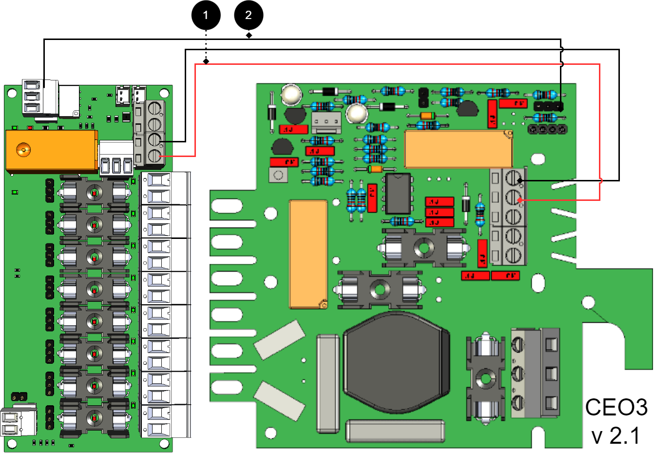
+ and - from load on motherboard are connected to + and - on the option board.
Communication is connected between terminals as the solid line shows.
Connecting the power supply
Connect power (24 V) from the battery backup's load output to the card's 24 V input.
Connection of load
Connect load wiring to P1:1-14 on fuse module for priority load. P1:15-20 for non-priority cargo. (Cards supplied with T2A fuses).
Caution
Maximum load is 5 A per load output, and the card's total load must not exceed 16 A.
No | Connections | 8 Output control module | Motherboard |
|---|---|---|---|
1 | Power supply connection: | P1:3-4 | Load output 1 |
2 | Alarm output: connected between NO and Com | P3: 1-3 (2-3) | JU3 Connects between the middle pin and an outer pin. |
- | Bridging alarms to the card is not possible as the card has no alarm input. | - | - |
Connect 8 Output control module to motherboard: CEO3 v5
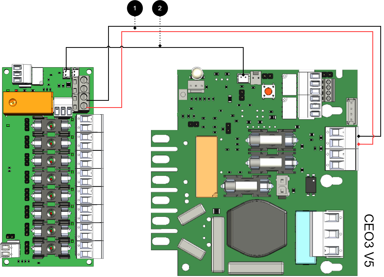
+ and - from load on motherboard are connected to + and - on the option board.
Communication is connected between terminals as the solid line shows.
Connecting the power supply
Connect power (24 V) from the battery backup's load output to the card's 24 V input.
Connection of load
Connect load wiring to P1:1-14 on fuse module for priority load. P1:15-20 for non-priority cargo. (Cards supplied with T2A fuses).
Caution
Maximum load is 5 A per load output, and the card's total load must not exceed 16 A.
No | Connections | 8 Output control module | Motherboard |
|---|---|---|---|
1 | Power supply connection: | P1:3-4 | Load output 2 |
2 | Bridging alarm to motherboard: Bridging of alarms to additional option cards | J14 J15 | J27 |
Connect 8 Output control module to motherboard: NEO3
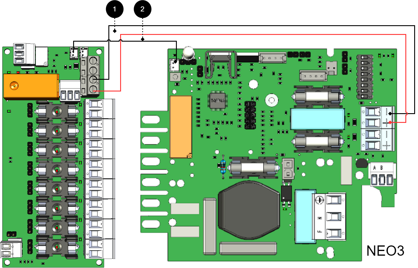
+ and - from load on motherboard are connected to + and - on the option board.
Communication is connected between terminals as the solid line shows.
No | Connections | 8 Output control module | Motherboard |
|---|---|---|---|
1 | Power supply connection: | P1:3-4 | Load output 2 |
2 | Bridging alarm to motherboard: Bridging of alarms to/from additional option cards | J14 J15 | J5 |
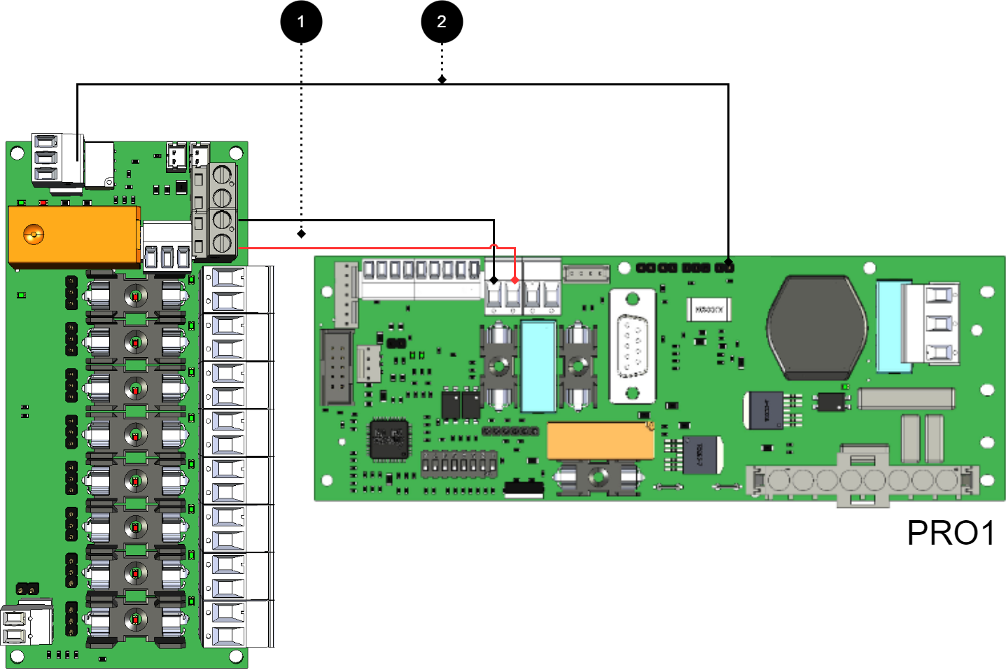
Connect 8 Output control module for motherboard: PRO1 5 A and 10 A
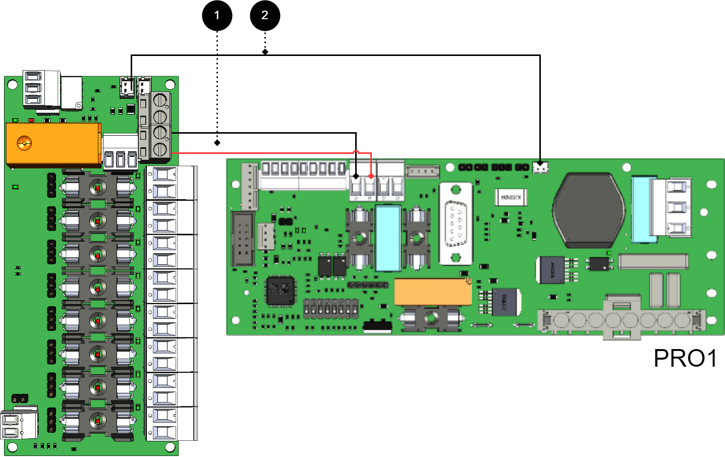
+ and - from load on motherboard are connected to + and - on the option board.
Communication is connected between terminals as the solid line shows.
No | Connections | 8 Output control module | Motherboard |
|---|---|---|---|
1 | Power supply connection: | P1:3-4 | Load output 1 |
2 | Bridging alarm to motherboard: Bridging alarms to/from additional option cards: | J14 J15 | J13 - |
Connect 8 Output control module for motherboard: PRO1 15 A and 25 A
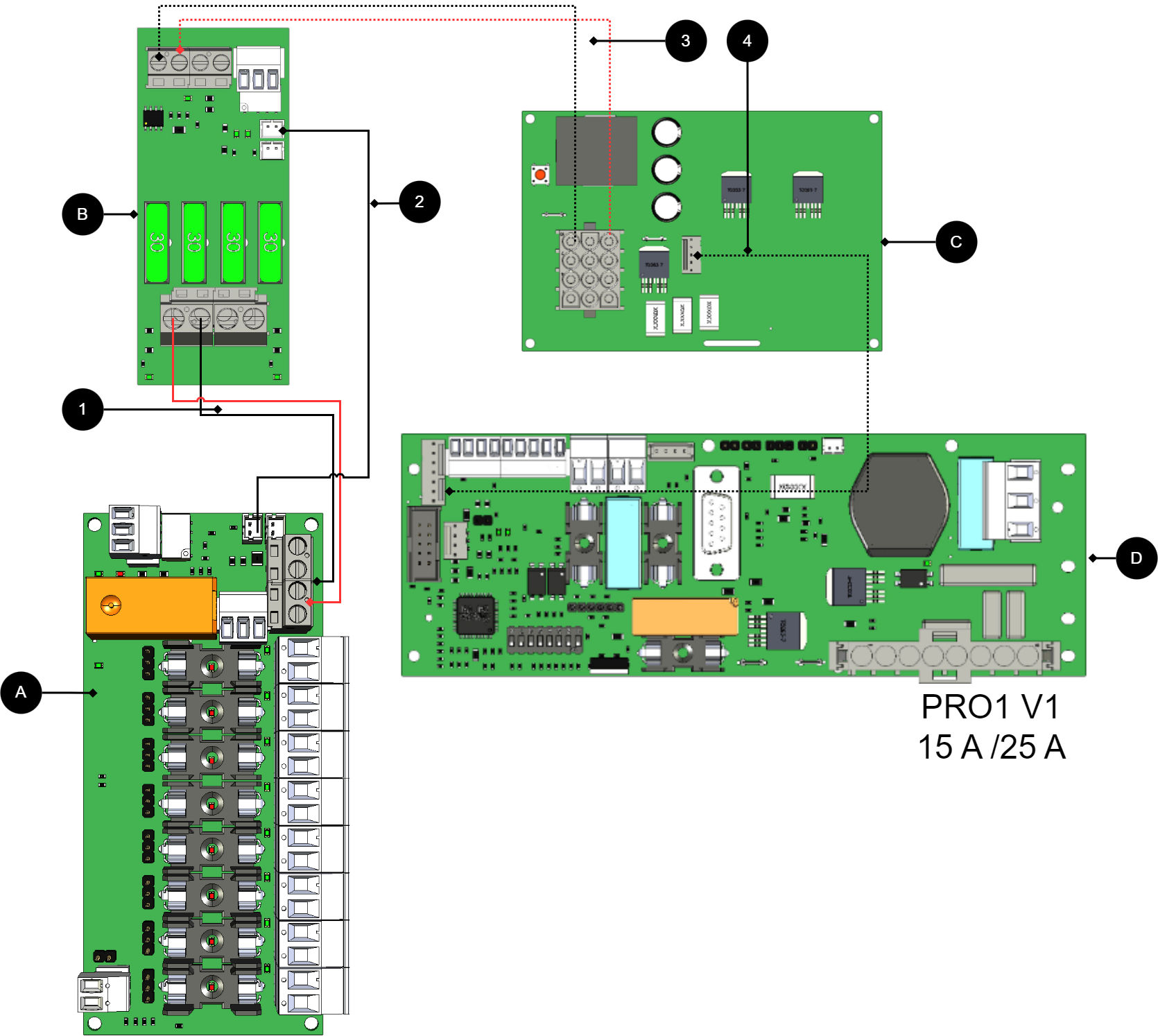
+ and - from load on motherboard are connected to + and - on the option board.
Communication is connected between terminals as the solid line shows.
No/letter | On circuit board (A) | Explanation |
|---|---|---|
A | 8 Output modules | Optional location. |
B | 2 Output module | Card for connection of load and power supply to 8 Output control module. |
C | Effect card | Available in 15 A and 25 A units. |
D | PRO1 | Motherboard in battery backup. |
1 | P1:3-4 | Connect power supply 8 Output control module from (B). |
2 | J14 | Alarms are connected to load card. |
3, 4 | - | Internal power supply and communication between cards. |
Connect 8 Output control module to motherboard: PRO2 v3
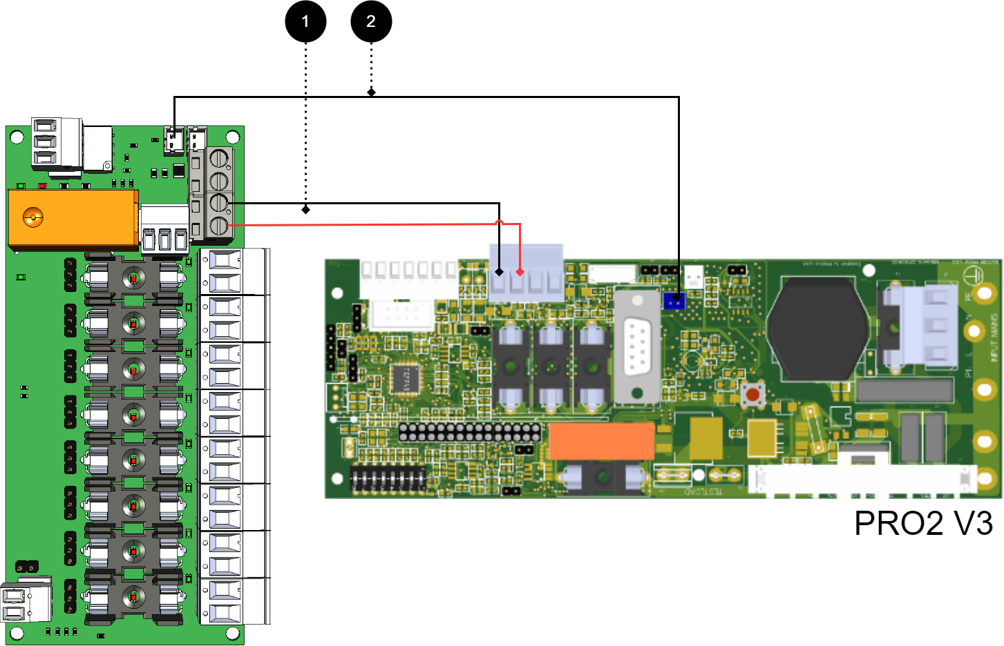
+ and - from load on motherboard are connected to + and - on the option board.
Communication is connected between terminals as the solid line shows.
No | Connections | 8 Output control module | Motherboard |
|---|---|---|---|
1 | Power supply connection: | P1:3-4 | Load output 1 |
2 | Bridging alarm to motherboard: Bridging alarms to additional option cards: | J14 J15 | J1 |
Connect 8 Output control module for motherboards: PRO2 v3 15 A and 25 A
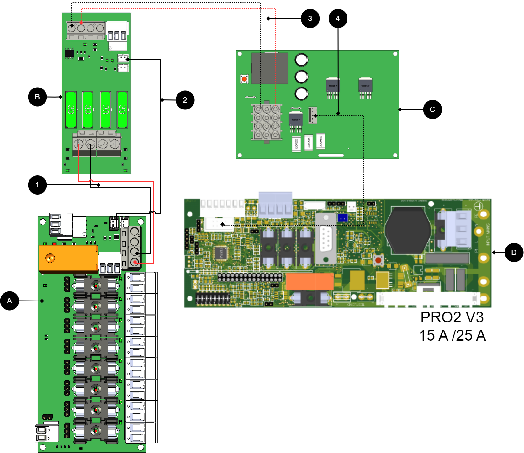
+ and - from load on motherboard are connected to + and - on the option board.
Communication is connected between terminals as the solid line shows.
No/letter | On circuit board (A) | Explanation |
|---|---|---|
A | 8 Output control module | Optional location. |
B | 2 Output module | Card for connection of load and power supply to 8 Output control module. |
C | Effect card | Available in 15 A and 25 A units. |
D | PRO2 v3 | Motherboard in battery backup. |
1 | P1:3-4 | Disconnect power supply 8 Output control module (B). |
2 | J14 | Connect alarm to load card. |
3, 4 | - | Internal power supply and communication between cards. |
Connect 8 Output control module to motherboard: PRO3
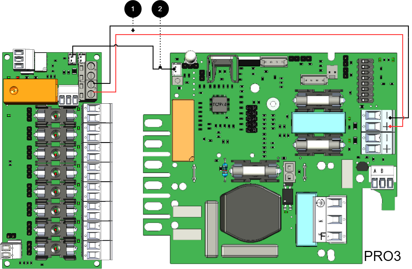
+ and - from load on motherboard are connected to + and - on the option board.
Communication is connected between terminals as the solid line shows.
No | Connections | 8 Output control module | Motherboard |
|---|---|---|---|
1 | Power supply connection: | IN 12 V / 24 V | Load output 2 |
2 | Bridging alarm to motherboard: | J11 | J5 |
If the card lacks a white (JST) contact or if the alarm is to be given via relay switching
Older cards[1] which lacks a JST contact, then the alarm is connected via relay switching. P3:1-3
No | Connections | 10 Output module | Motherboard |
|---|---|---|---|
1 | Power supply connection: | IN 12 V / 24 V | Load output 1 |
2 | Alarm output: | P3:1-3 | J13 |
Connection of another 8 Output module
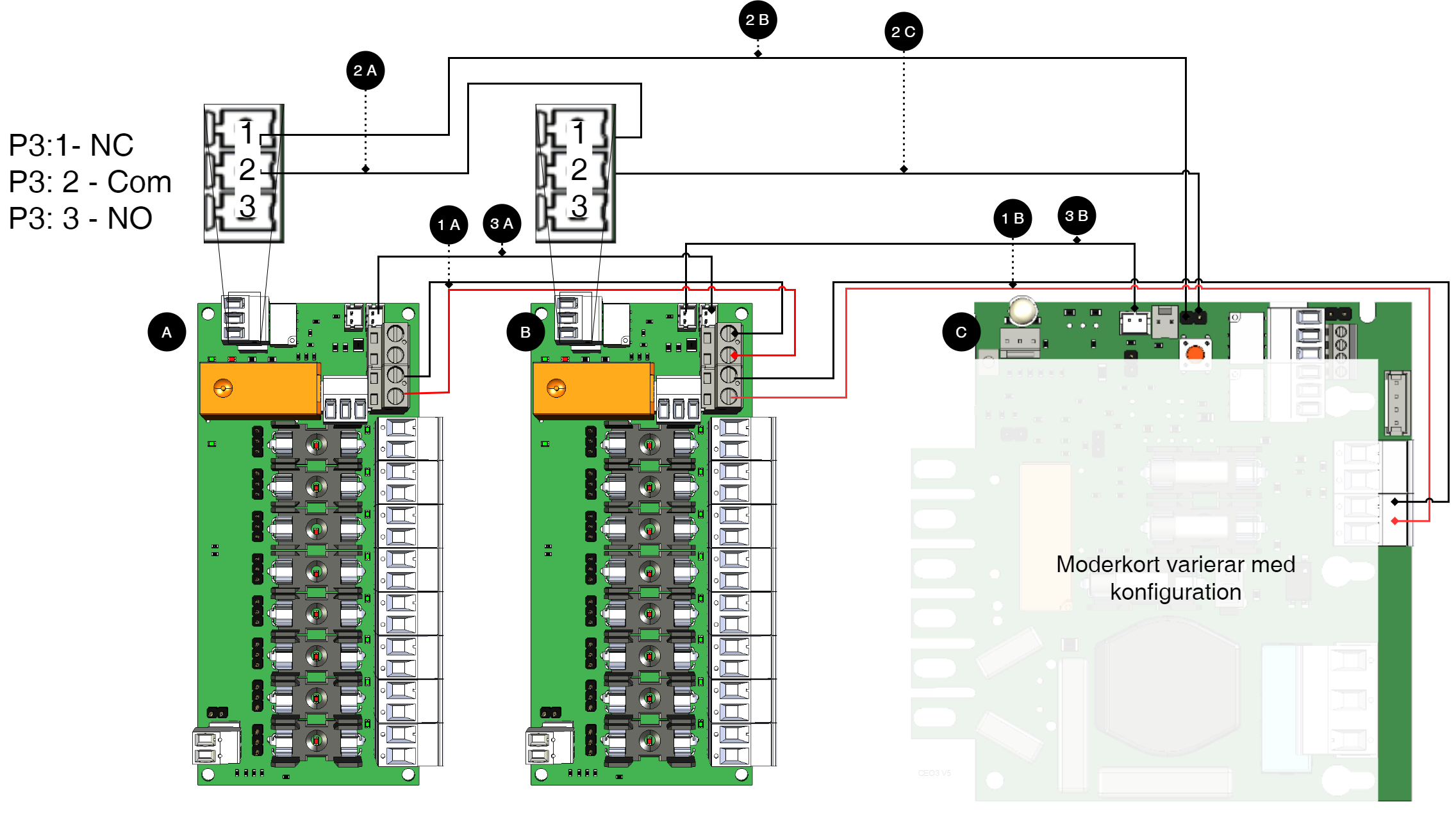
Note
For alarm connection use 2A and 2B for connection of newer devices (after approx. 2018). For older devices (before approx. 2018) use 3A-3C.
Letter / No | Explanation | On the card |
|---|---|---|
A | 8 Output control module. | - |
B | 8 Output control module. | - |
C | Motherboard, may vary with configuration. | - |
1 A | Power supply to 1B from 1A. | P1:1-+2 |
1 B | Power supply to 1B from motherboard. | P1:3-4 |
2 A | Bridging of alarms to card B. | J15 |
2 B | Connection of alarm on C (motherboard) from board A. | See table below. |
2C | Connection of alarm on C (motherboard) from board B. | See table below. |
3 A | Alarm output switches on C (motherboard). | P3:1-3 |
3 B | Alarm output is connected to C (motherboard). | P3:1-3 |
Technical data - 8 Output control module
Info | Explanation |
|---|---|
Card name: | 8 Output control module |
Product description | 8 Output control module is a protection module with 10 fully protected outputs, of which seven are prioritized and three are non-prioritized. |
The product fits in | Battery backups with motherboard: PRO1, PRO2, PRO2 V3, PRO3 and NEO3. |
Measure | 120 x 45 mm. |
Own consumption | 65mA |
Output voltage | 24 V |
Fuses | F2A comes with cards. |
Indication | Yes, LED on circuit board |
Info | Value |
|---|---|
Alarm outputs, number | 1 |
Alarm on changing relay? (Yes No) | Yes |
Load outputs, number | 8 |
Voltage on load output | 27.3V DC |
Voltage limit, upper, on load output | 27.9V DC |
Voltage limit, lower, on load output. With battery operation and disconnected mains voltage. | 20V DC |
Priority (always voltage) load outputs (Yes/No) | Yes |
Max load, per output | 10 A |
Maximum load, total, (must not be exceeded). | 16 A |
Load output plus (+) fused? (Yes No) | Yes |
Load output minus (-) secured (Yes/No) | No |
Fuses on output | T2A. |
Connection to buzzer? (Yes No) | No |
About translation of this document
User manual and other documents are in the original language in Swedish. Other languages are machine translated and not reviewed, errors may occur.
Address and contact details
Milleteknik AB |
Ögärdesvägen 8 B |
S-433 30 Partille |
Sweden |
+46 31 340 02 30 |
info@milleteknik.se |
www.milleteknik.com |