Technical specifications5 Output module
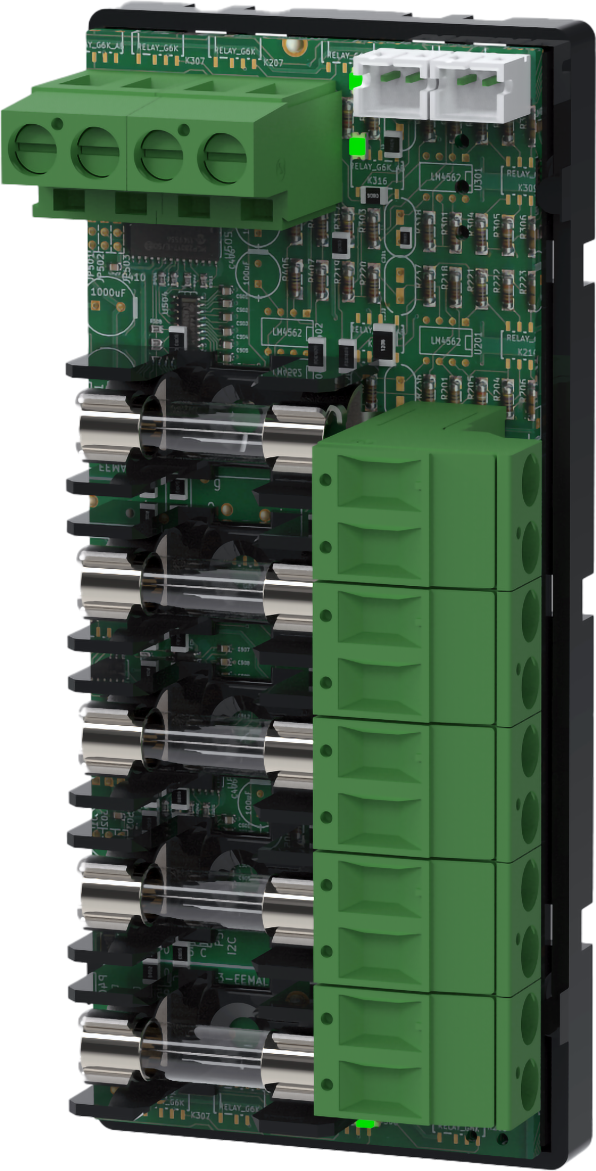
5 Output module is a fuse module with five fully fused outputs. When ordering, check that the card fits the battery backup the card is to be installed in.
Installation and commissioning
Mounting in battery backup
The card is delivered mounted in it's plastic casing, for easy installation.
If the card has come loose, snap it back into the plastic casing.
Mount the card on any card slot in the enclosure, leave space for cables.
Important
Install the board before screwing on wiring or commissioning.
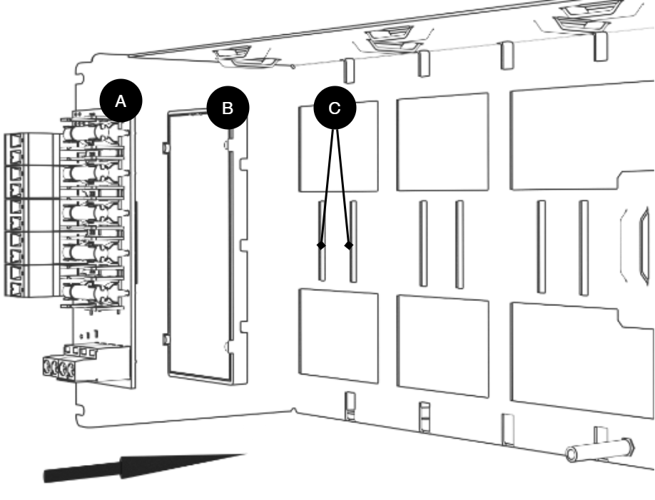
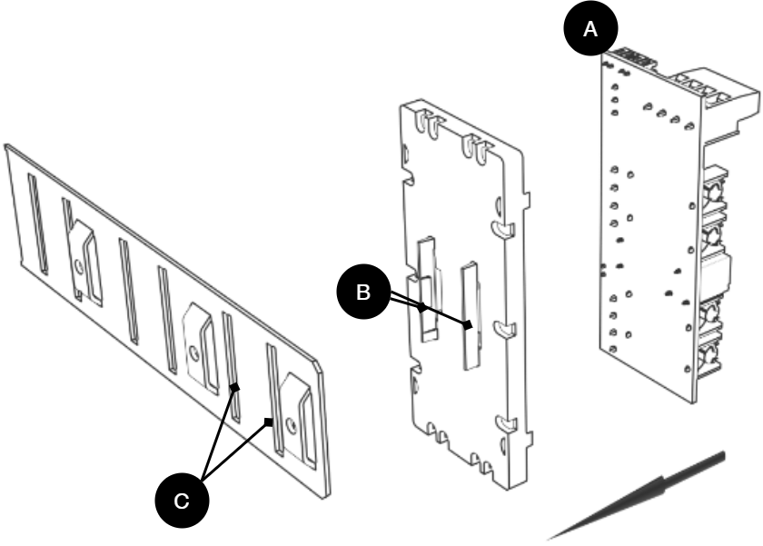
Letter | Explanation | Comment |
|---|---|---|
A | Optional card | Optional card comes mounted on plastic housing from factory. Has it come loose? Snap it back on before mounting the card. |
B | Plastic casing | The plastic casing has hooks for attaching slots in the plate. |
C | Place for plastic casing | Slits in sheet metal to snap the plastic bracket. |
Card description 5 Output module
[sv] Last kopplas in på 9, nedan.
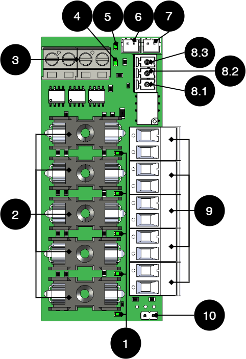
Nr | On circuit boards | Explanation |
|---|---|---|
1 | D1-D4 | Green indicator LED, illuminates with a solid green light when the fuse is ok. |
2 | F1-F5 | Fuses |
3 | J22, J23 | Incoming voltage from motherboard, 24 V. |
4 | D29 | Red indicator LED, illuminates with a solid green light when a fuse is broken. |
5 | D30 | Green indicator LED, illuminates with a solid green light when the fuse is ok. |
6 | J6 | Connection to alarm on motherboard. |
7 | J7 | Bridging connection for alarms from another card. |
8.1 | P3: 1-3 | Alarm output, NC. |
8.2 | P3:2 | Alarm output, Com, |
8.3 | P3:3 | Alarm output, NO, |
9 | P2: 1-10 | Load output +/- |
10 | JU4 | Jumper for setting the voltage in the card. Unbuilt = 24 V (factory setting). Built = 12 V. * * The card must have the same voltage as the motherboard. |
Use the supplied cable
Use the cable that comes with the box to connect the card.
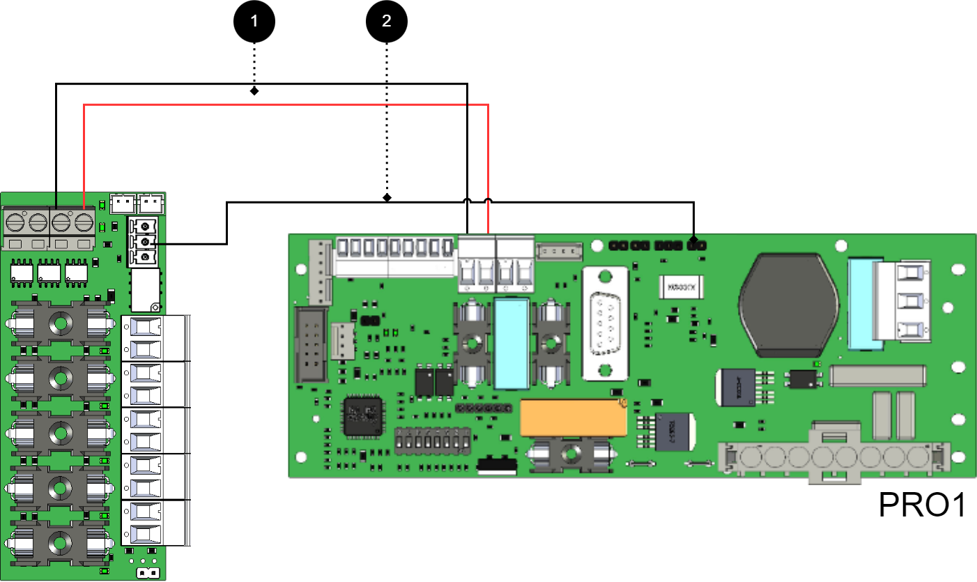
Connect 5 Output module for motherboard: CEO3 v2.1
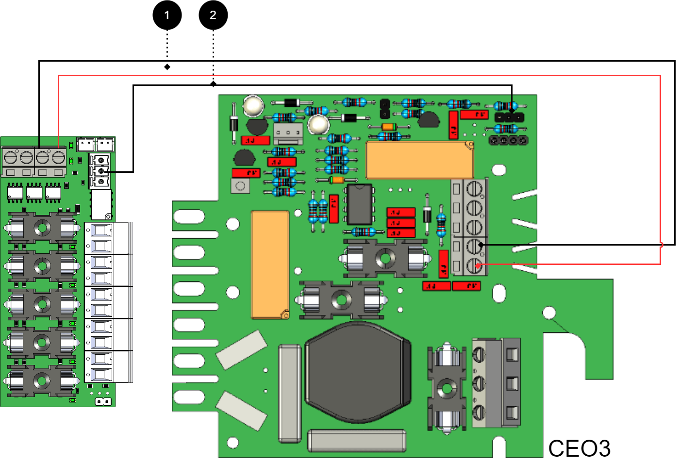
+ and - from load on motherboard is connected to + and - on the option card.
Communication is connected between terminals as the solid line shows.
Nr | Couplings | 5 Output module | Motherboard |
|---|---|---|---|
1 | Power supply connection: | IN 12 V / 24 V | Load output 1 |
2 | Alarm output: switched between NO and Com. | J6 | JU3 - connect middle pin and one outer pin. |
Connect 5 Output module for motherboard: CEO3 v5
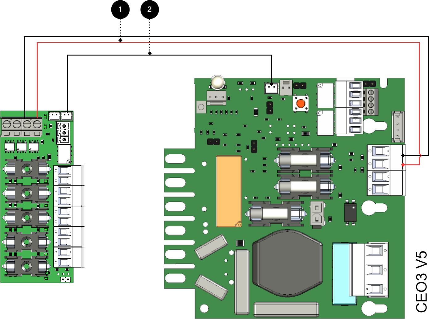
+ and - from load on motherboard is connected to + and - on the option card.
Communication is connected between terminals as the solid line shows.
Nr | Couplings | 5 Output module | Motherboard |
|---|---|---|---|
1 | Power supply connection: | IN 12 V / 24 V | Load output 1 |
2 | Connection to alarm on motherboard or bridging of alarm to another 5 Output module | J6 J7 | J27 - |
Connect 5 Output module for motherboard: NEO3
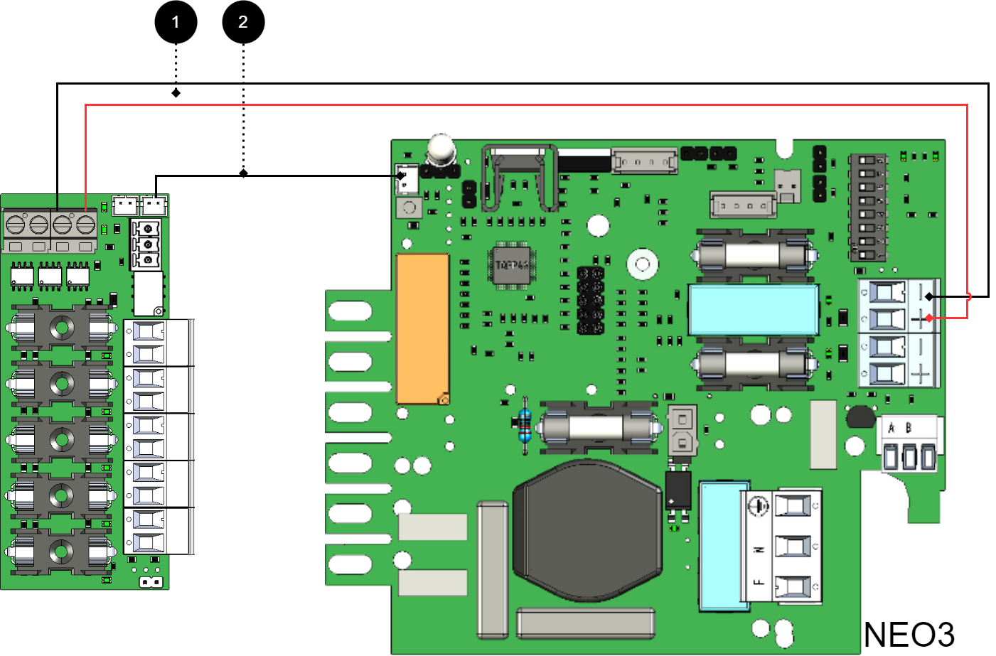
+ and - from load on motherboard is connected to + and - on the option card.
Communication is connected between terminals as the solid line shows.
Nr | Couplings | 5 Output module | Motherboard |
|---|---|---|---|
1 | Power supply connection: | IN 12 V / 24 V | Load output 1 |
2 | Connection to alarm on motherboard: bridging of alarms to / from additional option cards | J6 J7 | J5 - |
Connect 5 Output module for motherboard: PRO2 v3 15 A and 25 A
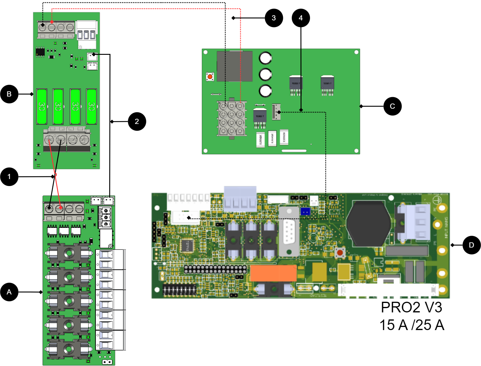
No. / letter | circuit board | Explanation |
|---|---|---|
C | Power card | Available only on 15 A and 25 A units. |
D | Motherboard | PRO2 v3 |
2 | J7 | Connect alarm to load card. |
1 | IN 24 V | Connect power supply from 2 output modules. |
A | 5 Output module | Option card. |
B | 2 Output module | Connect power supply (24 V) to 5 Output module. |
3, 4 | - | Internal power supply and communication between cards. |
If the card lacks a white (JST) contact or if the alarm is to be given via relay switching
+ and - from load on motherboard are connected to + and - on the option board.
Communication is connected between terminals as the solid line shows.
No | Connections | 5 Output module | Motherboard |
|---|---|---|---|
1 | Power supply connection: | IN 12 V / 24 V | Load output 1 |
3 | Alarm output: | P3:1-2 | J15 |
Connection of additional 5 Output module
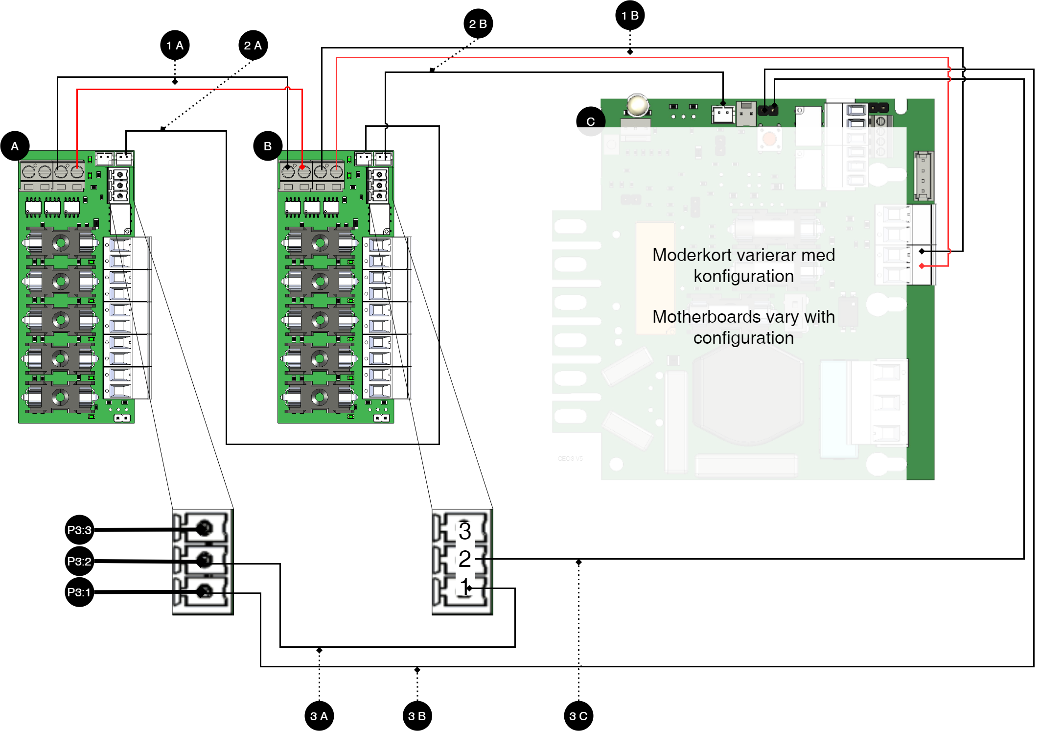
Note
For alarm connection use 2A and 2B for connection of newer devices (after approx. 2018). For older devices (before approx. 2018) use 3A-3C.
Letter / No. | Explanation | On the card |
|---|---|---|
A | 5 Output module. | - |
B | 5 Output module. | - |
C | Motherboard, varies with configuration. | - |
1 A | Power supply from 1B. | IN 24 V |
1 B | Power supply from C (motherboard). | IN 24 V |
2 A | Bridging of alarm to card B. | J7 |
2 B | Connection of alarm on C (motherboard) from card A | See table below. |
3 A | Jumper between cards A and B. | P3: 1-3 |
3 B | Alarm output switches on C (motherboard). | P3: 1-3 |
3 C | Alarm output is connected to C (motherboard). | P3: 1-3 |
P3 | Explanation |
|---|---|
P3:1 | NC |
P3:2 | Com |
P3:3 | NO |
Technical data - 5 Output module
Info | Explanation |
|---|---|
Short name: | 5 Output module |
Product description | 5 Output module is a fuse module with five fully fused outputs. |
The product fits in | Battery backups with motherboards: PRO1, PRO2, PRO2 V3, PRO3 and NEO3. |
Measure | 85 x 37 mm |
Own consumption | 35 mA |
Tension | 12 V or 24 V |
Fuses | On load outputs. |
Indication | Yes, LED on circuit board |
Info | Explanation |
|---|---|
Alarm outputs, number | 1 |
Alarm on alternating relay? (Yes No) | Yes, sum alarm in case of fuse fault |
Alarm output protocol (communication protocol) | - |
Load outputs, number | 5 |
Voltage at load output | 27.3 V DC |
Voltage limit, upper, on load output | 27.9 V DC |
Voltage limit, lower, on load output. For battery operation and disconnected mains voltage. | 20 V DC |
Priority (always voltage) load outputs (Yes / No) | Yes |
Maximum load, per output | 10 A |
Maximum load, total, (must not be exceeded). | 16 A |
Load output plus (+) secured? (Yes No) | Yes |
Load output minus (-) secured (Yes / No) | No |
Connection to buzzer? (Yes No) | No |
About translation of this document
User manual and other documents are in the original language in Swedish. Other languages may be machine translated and/or not reviewed, errors may occur.
Address and contact details
Milleteknik AB |
Ögärdesvägen 8 B |
S-433 30 Partille |
Sweden |
+46 31 340 02 30 |
info@milleteknik.se |
www.milleteknik.com |