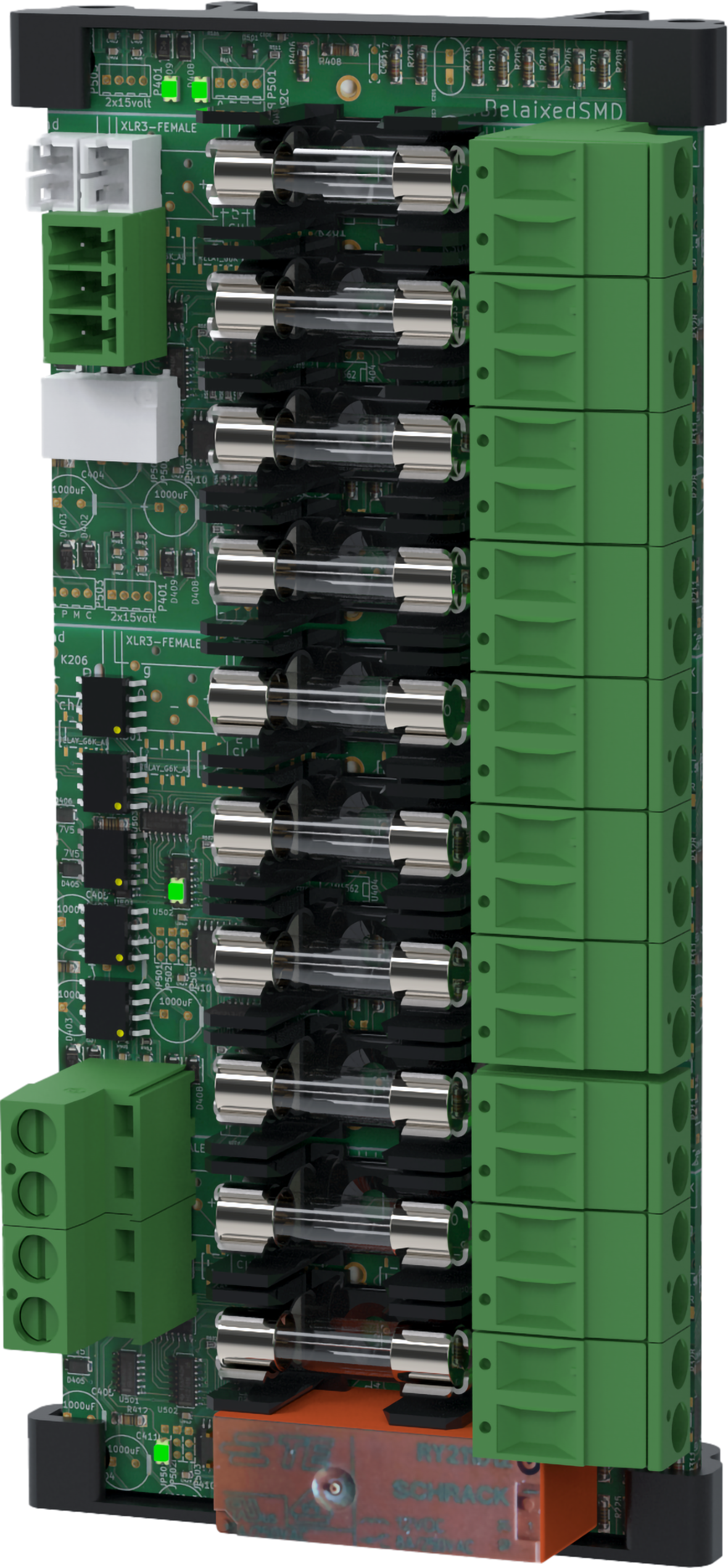
Technical specifications 10 Output module
10 Output module is a protection module with 10 fully protected outputs, of which seven are prioritized and three are non-prioritized. The card is mounted on sheet metal in battery backup or via nylon fasteners. When ordering, check that the card fits the battery backup card to be installed in.
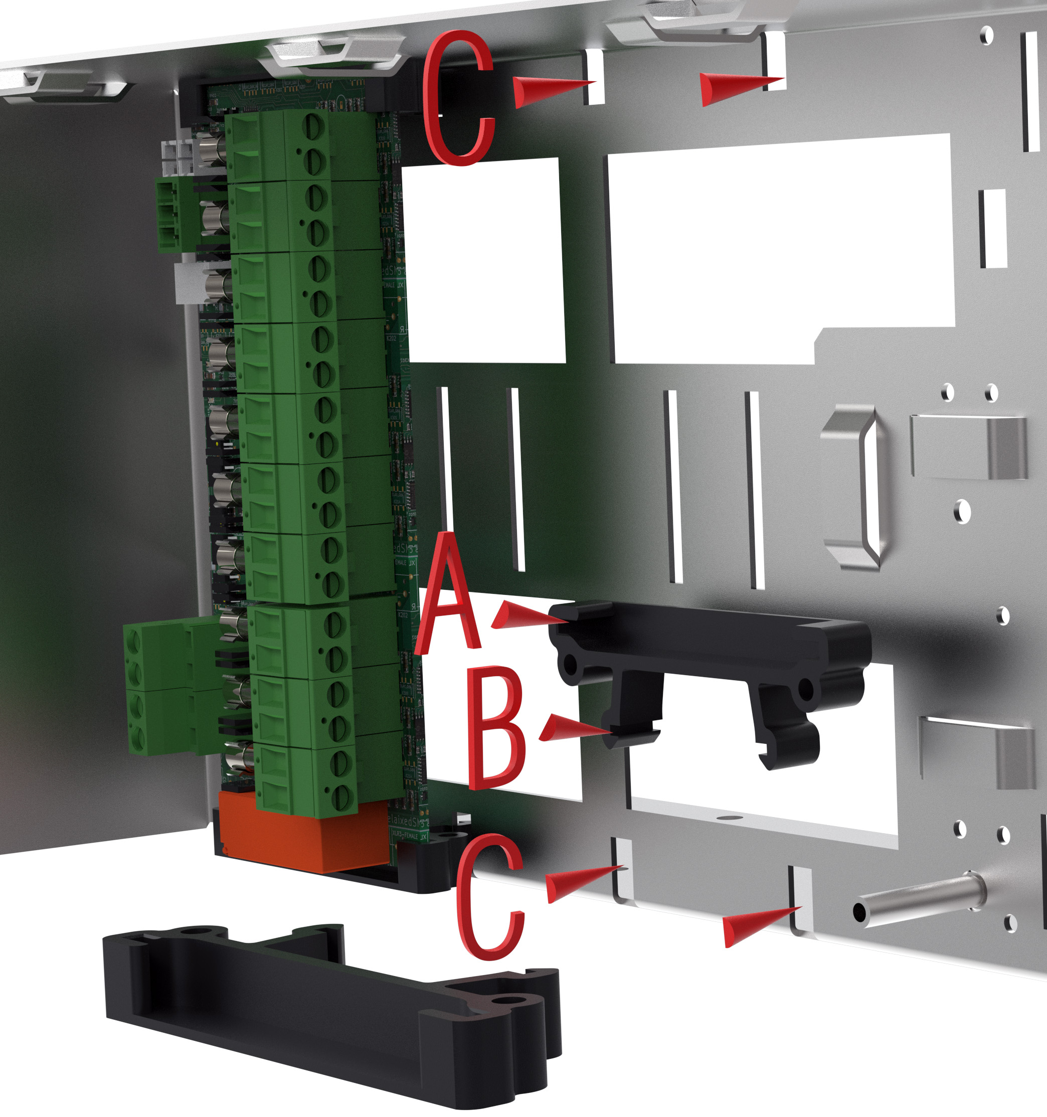
Installation in battery backup
Mount the card in any card slot in the enclosure, leave plenty of room for cables.
Check that the card fits with the device before mounting. Even if the card fits mechanically, it is not guaranteed to be supported electrically. It is the responsibility of the installer that the card is compatible with battery backup.
Note
Install and connect option cards before commissioning battery backup.
Letter | Explanation |
|---|---|
A | The card must sit in the plastic spacers with the connections on the card facing up. |
B | Hooks to attach to the plate (C). |
C | Snap on plastic spacers. |
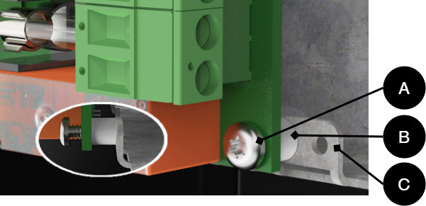
Installation directly on sheet metal in battery backup
If the battery backup lacks fasteners for plastic spacers, the card can be screwed directly into the plate.
The plate has flaps that must be folded down and the card must be screwed into these.
Plastic spacers must be placed between the card and the plate to avoid a short circuit in the card.
Note
Install and connect option cards before commissioning battery backup.
Letter | Explanation |
|---|---|
A | Torx, M2.9 x 9.5 mm. |
B | Plastic spacer, M3 x 4 mm. |
C | Tab that folds in before the card is screwed on. |
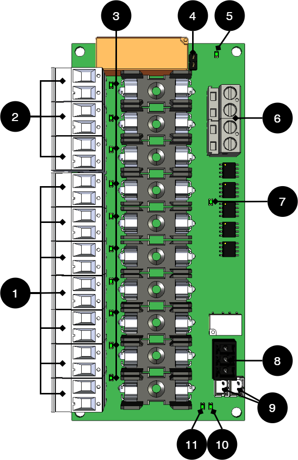
Card description 5 Output module
Important
From the factory, all ten outputs are prioritized, (4 are jumpered).
No . | On circuit board | Explanation |
|---|---|---|
1 | P1:1-14 | Priority load outputs -/+. (Odd numbers = minus, even numbers = plus). A prioritized load output always has voltage. |
2 | P1:15-20 | Unprioritized load outputs -/+. (Odd numbers = minus, even numbers = plus). In battery operation, the load is released if 4 is not bridged. If the jumper is on 4, the load outputs are prioritized. |
3 | D1-D10 | Green indicator diode, lights up with a solid green light when the fuse is ok. |
4 | JU1 | Jumper to control three outputs. Factory setting is mounted jumper = all 10 outputs are activated. Without a jumper, only priority outputs (1) P1:1-14 are activated. If the jumper is removed, the outputs, 2, are controlled from 9. |
5 | D10 | Green indicator diode, lights up with a solid green light when all outputs are activated. |
6 | P2:1-4 | Incoming voltage from motherboard, 24 V. (1,3=+, 2,4=-). |
7 | D17 | Indicator diode lights up orange if priority outputs are activated. |
8 | P1:1-3 | Alarm output, NO, Com, NC. |
9 | J11-J12 | Connection of alarms to motherboard and/or bridging of alarms from another board. Use any connection to connect alarm to motherboard. If the jumper, 4, is removed, the outputs, 2, are controlled with the coupling, see connection to the board. |
10 | D29 | Indicator diode that lights up with a solid green light when all fuses are ok. |
11 | D30 | Indicator diode that lights up with a solid red light if any fuse is faulty. |
Use the supplied cable
Use the cable that comes with the box to connect the card.
Connect 10 Output module to motherboard: CEO3 v2.1
+ and - from load on motherboard are connected to + and - on the option board.
Communication is connected between terminals as the solid line shows.
Connecting the power supply
Connect power (24 V) from the battery backup's load output to the card's 24 V input.
Connection of load
Connect load wiring to P1:1-14 on fuse module for priority load. P1:15-20 for non-priority cargo. (Cards supplied with T2A fuses).
Caution
Maximum load is 5 A per load output, and the card's total load must not exceed 16 A.
No | Connections | 10 Output module | Motherboard |
|---|---|---|---|
1 | Power supply connection: | IN 12 V / 24 V | Load output 1 |
2 | Alarm output: connected between NO and Com | P3: 1-3 (2-3) | JU3 Connects between the middle pin and an outer pin. |
- | Bridging alarms to the card is not possible as the card has no alarm input. | - | - |
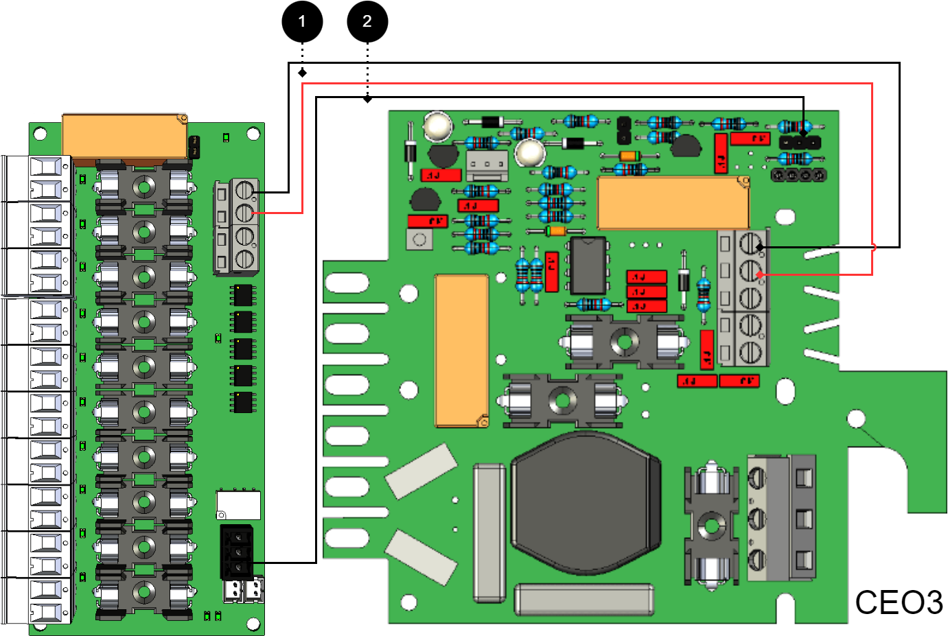
Connect 10 Output module to motherboard: CEO3 v5
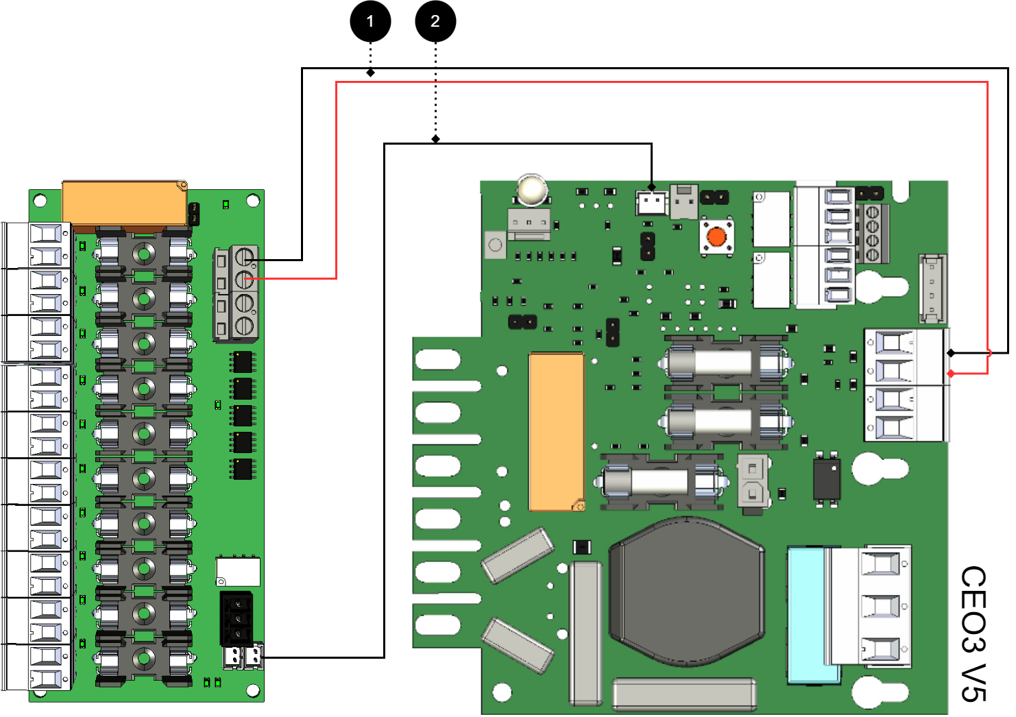
+ and - from load on motherboard are connected to + and - on the option board.
Communication is connected between terminals as the solid line shows.
Connecting the power supply
Connect power (24 V) from the battery backup's load output to the card's 24 V input.
Connection of load
Connect load wiring to P1:1-14 on fuse module for priority load. P1:15-20 for non-priority cargo. (Cards supplied with T2A fuses).
Caution
Maximum load is 5 A per load output, and the card's total load must not exceed 16 A.
No | Connections | 10 Output module | Motherboard |
|---|---|---|---|
1 | Power supply connection: | IN 12 V / 24 V | Load output 2 |
2 | Bridging alarm to motherboard: Bridging of alarms to another 10 Output module | J11 J11 or J12 | J27 J11 or J12 |
Connect 10 Output module to motherboard: NEO3
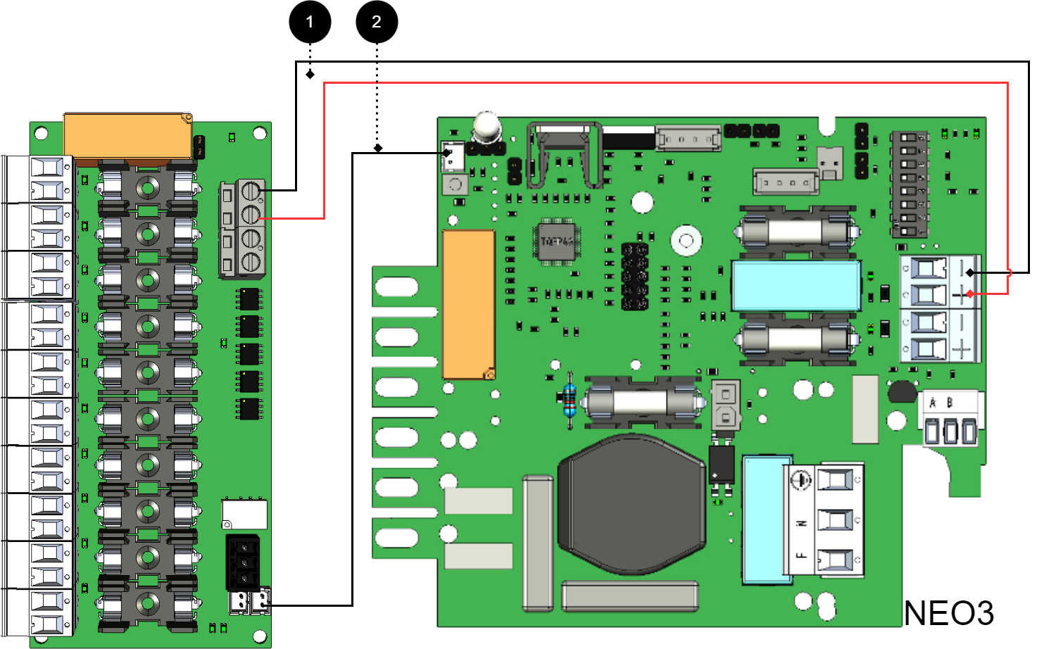
+ and - from load on motherboard are connected to + and - on the option board.
Communication is connected between terminals as the solid line shows.
No | Connections | 10 Output module | Motherboard |
|---|---|---|---|
1 | Power supply connection: | IN 12 V / 24 V | Load output 2 |
2 | Bridging alarm to motherboard: Bridging of alarms to/from additional option cards | J11 J12 | J5 |
Connect 10 Output module for motherboard: PRO1 5 A and 10 A
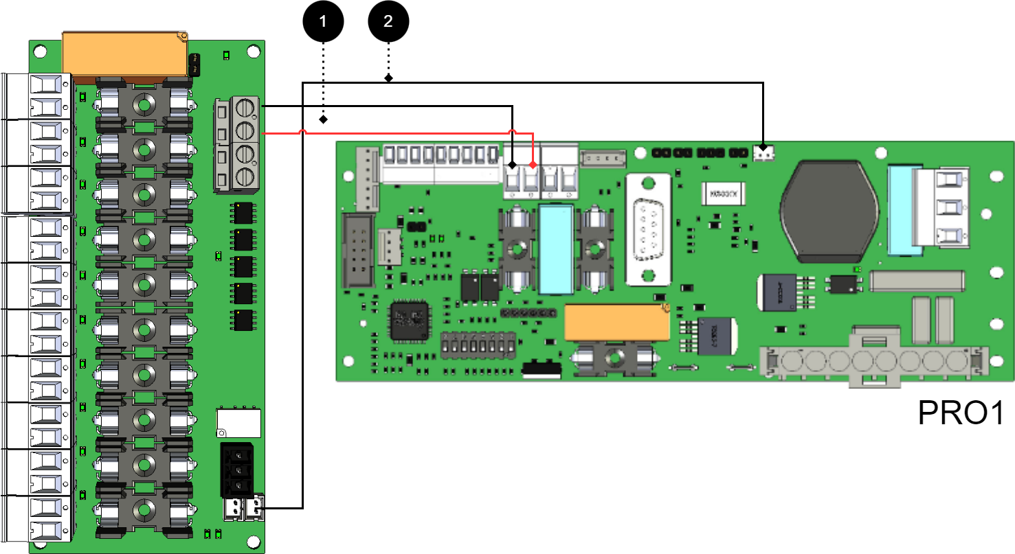
+ and - from load on motherboard are connected to + and - on the option card.
Communication is connected between terminals as the solid line shows.
Important
Early versions of PRO1 and PRO2 may lack white terminal (JST). which lacks a JST contact, then the alarm is connected via relay switching. P3:1-3.If the card lacks a white (JST) contact or if the alarm is to be given via relay switching
No . | Connections | 10 Output module | Motherboard |
|---|---|---|---|
1 | Power supply connection: | IN 12 V / 24 V | Load output 1 |
2 | Bridging alarm to motherboard: Bridging alarms to/from additional option cards: | J11 J12 | J13 - |
Connect 10 Output module for motherboard: PRO1 15 A and 25 A
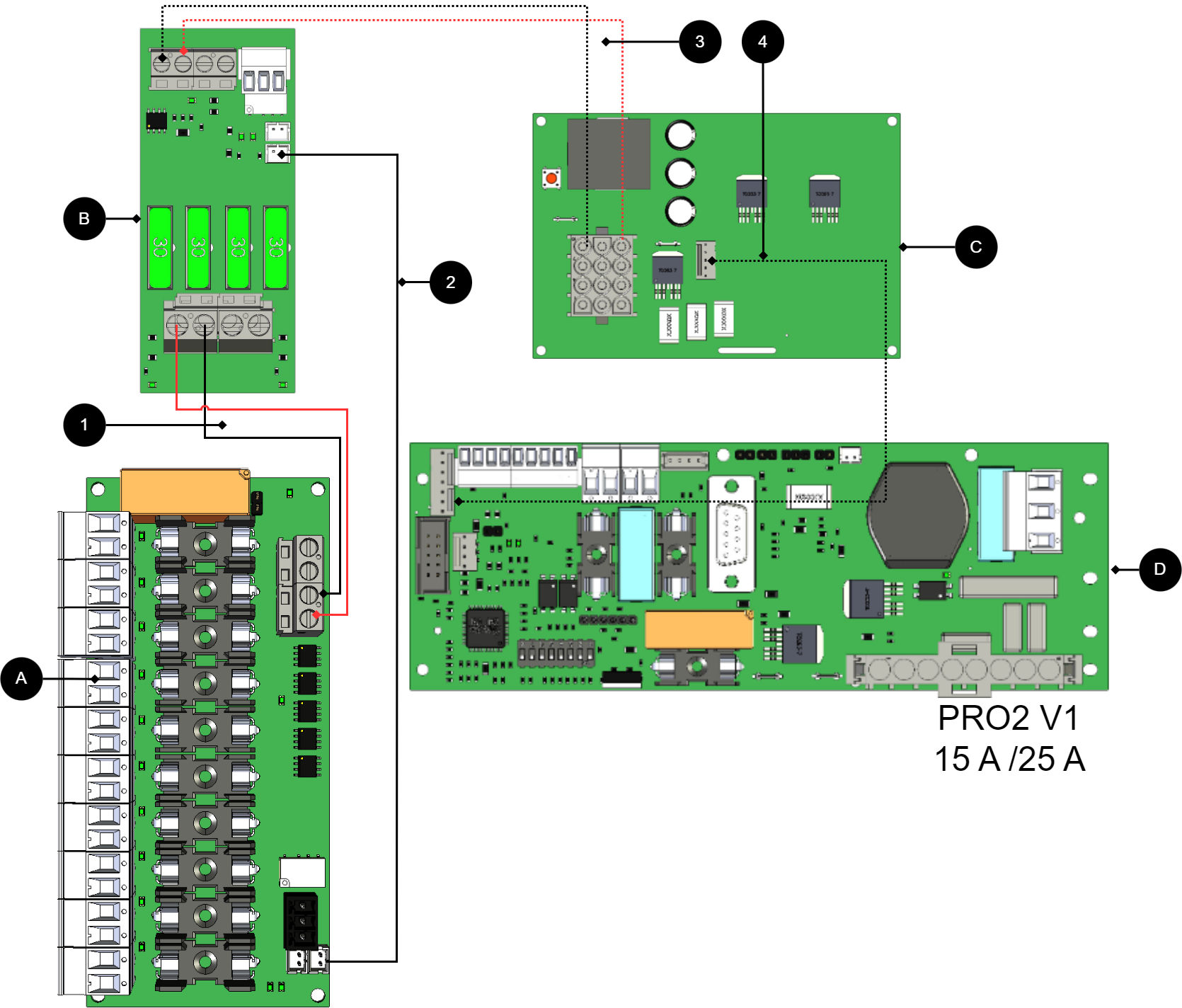
+ and - from load on motherboard are connected to + and - on the option card.
Communication is connected between terminals as the solid line shows.
No./letter | On circuit board (A) | Explanation |
|---|---|---|
A | 10 Output module | Optional card |
B | 2 Output module | Card for connection of load and power supply to 10 Output module. |
C | Effect card | In use in 15 A and 25 A units. |
D | PRO1 | Motherboard in battery backup. |
1 | IN 24 v | Connect power supply from 2 Output module (B). |
- | P3:1-3 | Alarm output is connected to J15 on motherboard (D). |
2 | J11 | Alarm output, connects to load card. |
3, 4 | - | Internal power supply and communication between cards. |
Connect 10 Output module for motherboards: PRO2 v3 15 A and 25 A
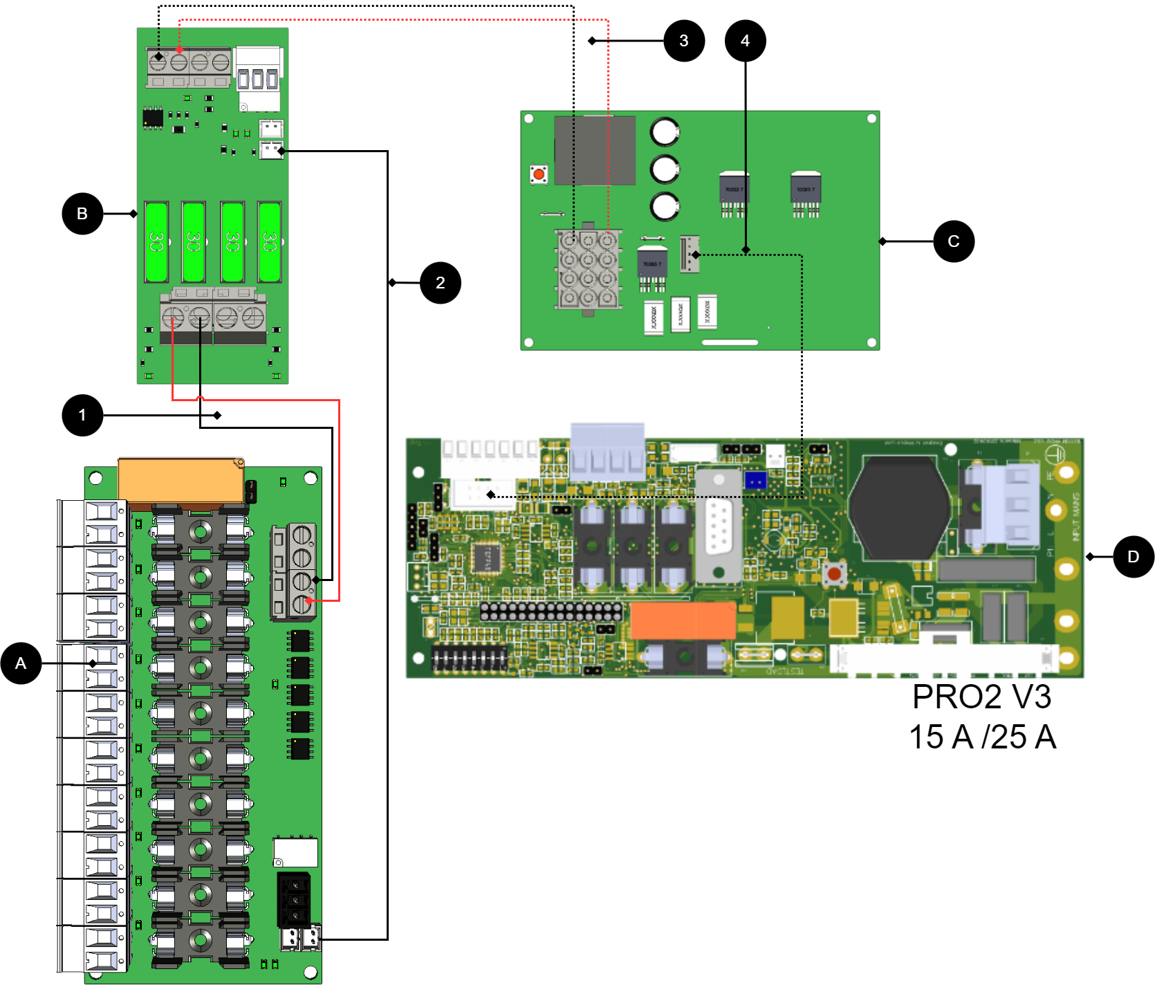
+ and - from load on motherboard are connected to + and - on the option board.
Communication is connected between terminals as the solid line shows.
Important
Early versions of PRO1 and PRO2 may lack white terminal (JST). which lacks a JST contact, then the alarm is connected via relay switching. P3:1-3.If the card lacks a white (JST) contact or if the alarm is to be given via relay switching
No/letter | On circuit board | Explanation |
|---|---|---|
A | 10 Output modules | Optional card. |
B | 2 Output module | Card for connection of load and power supply to 10 Output module. |
C | Effect card | Available in 15 A and 25 A units. |
D | PRO2 v3 | Motherboard in battery backup. |
1 | P2:3-4 | Connect power supply from 2 Output module (B) to 10 Output Module (A) |
2 | J11 | Alarm output, connects to load card. |
3,4 | - | Internal power supply between cards. |
Connect 10 Output module to motherboard: PRO3
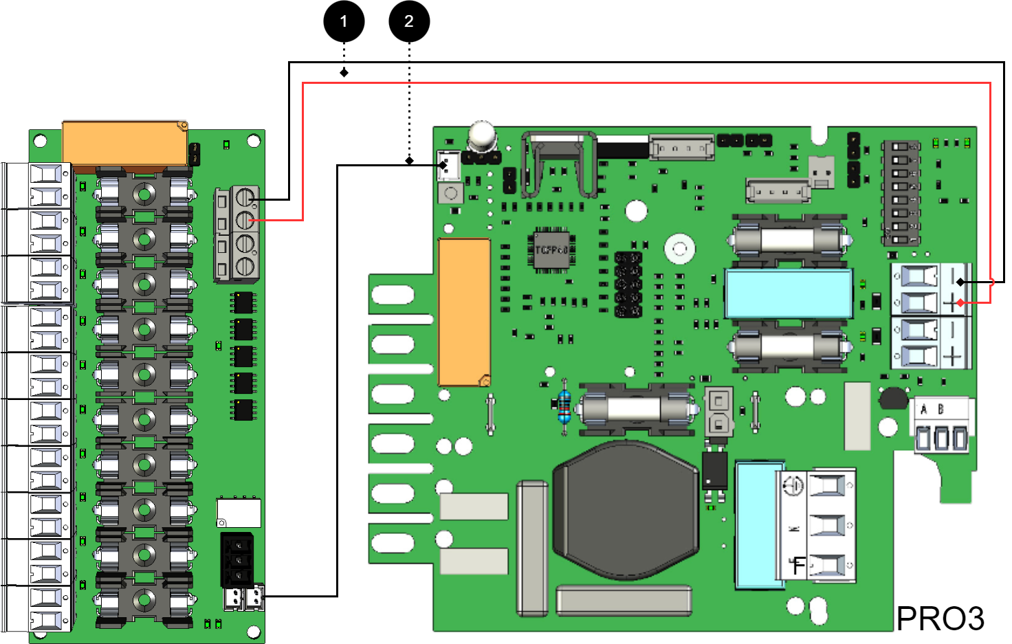
+ and - from load on motherboard are connected to + and - on the option board.
Communication is connected between terminals as the solid line shows.
No | Connections | 8 Output control module | Motherboard |
|---|---|---|---|
1 | Power supply connection: | IN 12 V / 24 V | Load output 2 |
2 | Bridging alarm to motherboard: | J11 | J5 |
If the card lacks a white (JST) contact or if the alarm is to be given via relay switching

Older cards[1] which lacks a JST contact, then the alarm is connected via relay switching. P3:1-3
No | Connections | 10 Output module | Motherboard |
|---|---|---|---|
1 | Power supply connection: | IN 12 V / 24 V | Load output 1 |
2 | Alarm output: | P3:1-3 | J13 |
Connection of another 10 Output module
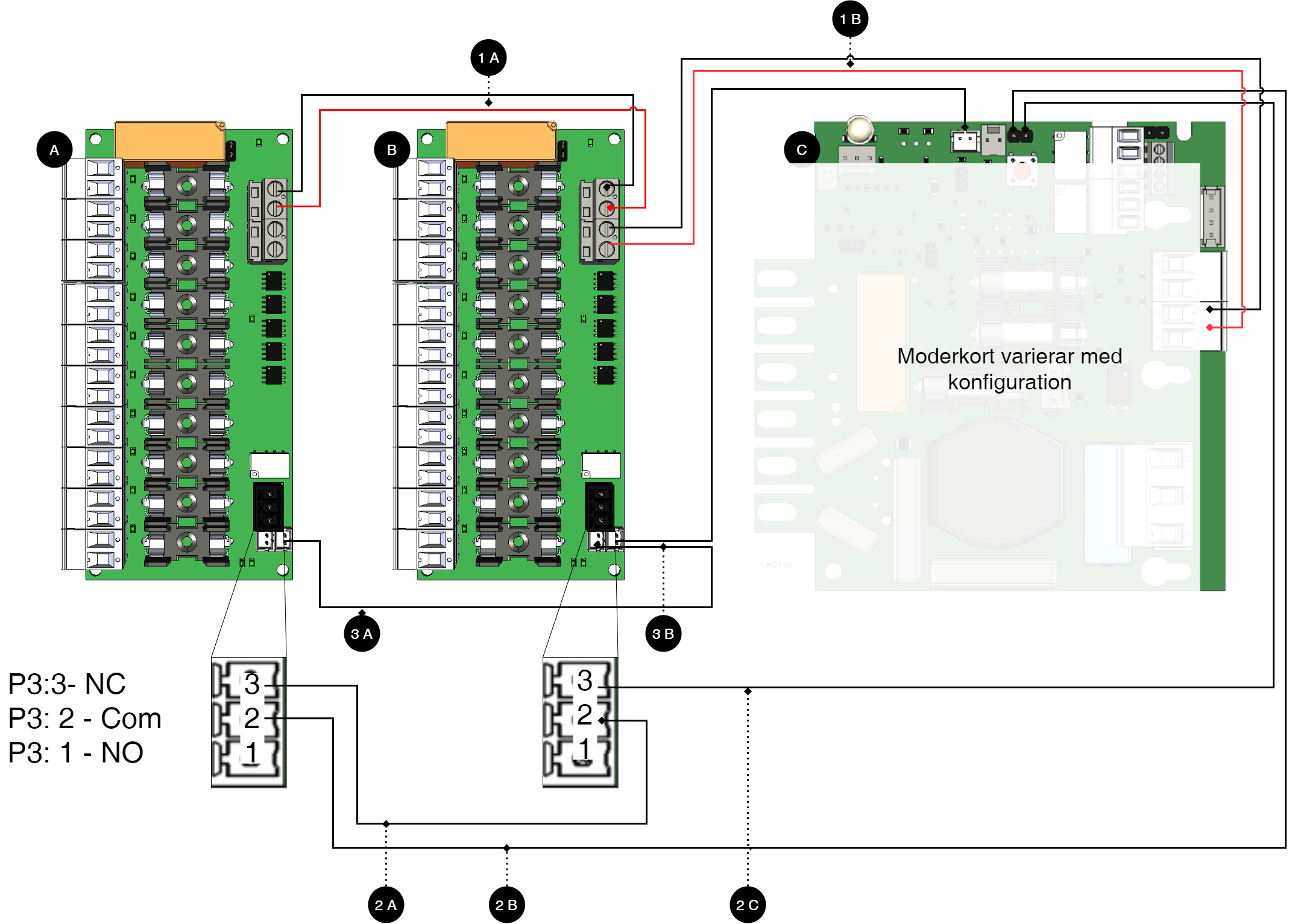
Note
For alarm connection use 2A and 2B for connection of newer devices (after approx. 2018). For older devices (before approx. 2018) use 3A-3C.
Letter / No | Explanation | On the card |
|---|---|---|
A | 10 Output modules. | - |
B | 10 output modules. | - |
C | Motherboard, may vary with configuration. | - |
1 A | Power supply from 1B. | IN 24 V |
1 B | Power supply from C (motherboard). | IN 24 V |
2 A | Bridging of alarms to card B. | J12 |
2 B | Connection of alarm on C (motherboard) from board A. | See table below. |
2C | Connection of alarm on C (motherboard) from board B. | See table below. |
3 A | Alarm output switches on C (motherboard). | P3:1-3 |
3 B | Alarm output is connected to C (motherboard). | P3:1-3 |
10 Output Module in delivered in housing
The card is also available mounted in a lockable enclosure.
Installation of enclosure B3
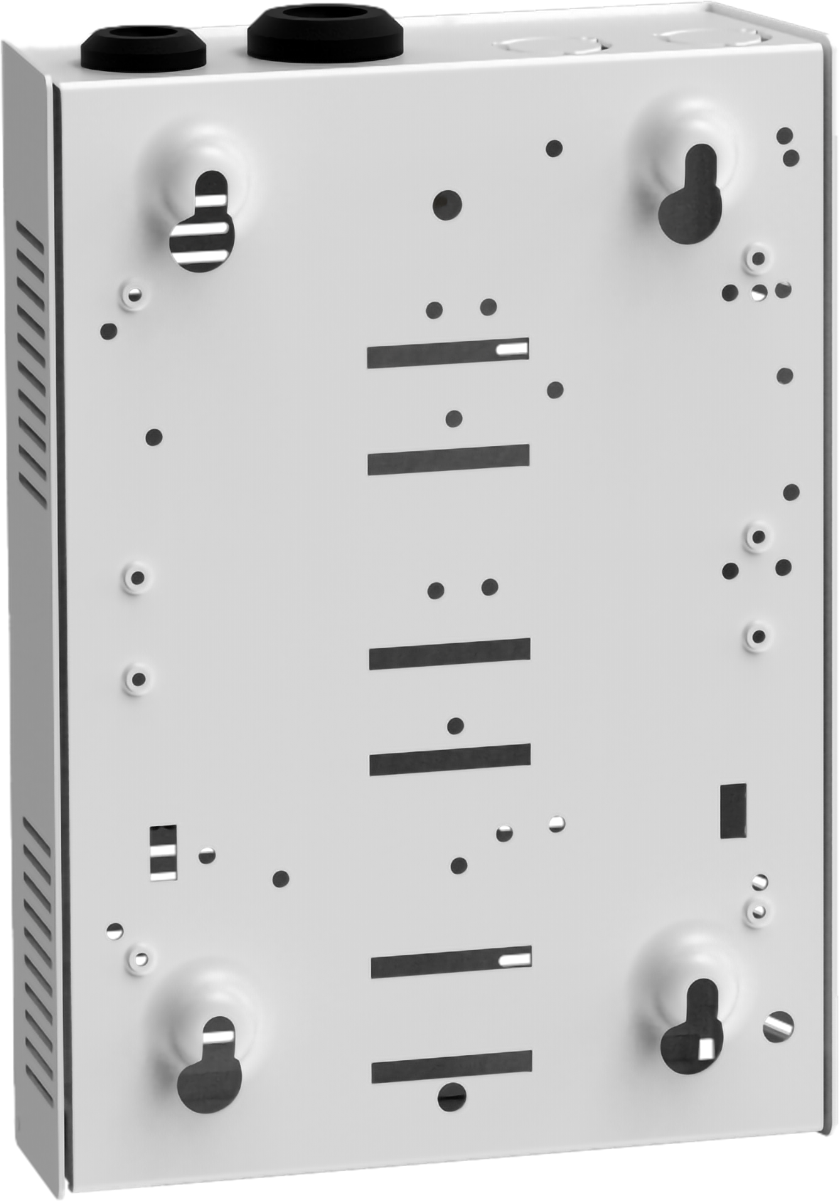
The B3 enclosure has four holes for wall mounting.
Cable entries are on the top side.
Technical data - 10 Output module
Info | Explanation |
|---|---|
Short name: | 10 Output module |
Product description | 10 Output module is a hedging module with 10 fully secured outputs, of which seven are prioritized and three are non-prioritized. |
The product fits in | Battery backups with motherboards: PRO1, PRO2, PRO2 V3, PRO3 and NEO3. |
Measure | 120 x 45 mm |
Own consumption | 70 mA |
Tension | 24 V |
Fuses | F10A |
Indication | Yes, LED on circuit board |
Info | Explanation |
|---|---|
Alarm outputs, number | 1 |
Alarm on alternating relay? (Yes No) | Yes, sum alarm in case of fuse fault |
Alarm output protocol (communication protocol) | - |
Load outputs, number | 10 |
Voltage at load output | 27.3 V DC |
Voltage limit, upper, on load output | 27.9 V DC |
Voltage limit, lower, on load output. For battery operation and disconnected mains voltage. | 20 V DC |
Priority (always voltage) load outputs (Yes / No) | Yes |
Maximum load, per output | 10 A |
Maximum load, total, (must not be exceeded). | 16 A |
Load output plus (+) secured? (Yes No) | Yes |
Load output minus (-) secured (Yes / No) | No |
Fuses on output | Yes, see table: Fuses. |
Connection to buzzer? (Yes No) | No |
About translation of this document
User manual and other documents are in the original language in Swedish. Other languages are machine translated and not reviewed, errors may occur.
Enclosures - Technical Data S
Info | Explanation |
|---|---|
Name | B3 |
Enclosure class | IP 20 |
Measure | Height: 200, width: 146, depth: 57 mm |
Mounting | Wall |
Ambient temperature | + 5 ° C - + 40 ° C. For best battery life: + 15 ° C to + 25 ° C. |
Environment | Environmental class 1, indoors. 20% ~ 90% relative humidity |
Material | Powder coated sheet |
Color | White |
Cable entries, number | 2 |
Batteries that fit | 1 pc 12 V 2.3 Ah or |
Place for fan | No |
Address and contact details
Milleteknik AB |
Ögärdesvägen 8 B |
S-433 30 Partille |
Sweden |
+46 31 340 02 30 |
info@milleteknik.se |
www.milleteknik.com |
[1] Early versions of PRO1 and PRO2 may lack white terminal (JST).