Alarm or warning and how quickly it should be addressed
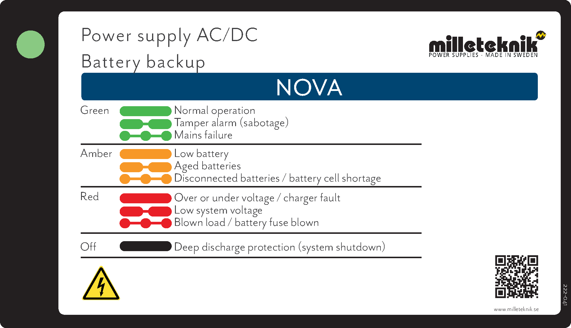 |
The indicator diode shows | Icon | Explanation | Status | Measure | |
|---|---|---|---|---|---|
Solid green light |
| Normal operation. | Information | Everything works normally, no action is needed. | |
Slow green blinks |
| Sabotage alarm. | Alarm | Tamper alarm, given when the battery backup door is open. If an alarm is given despite the door being closed, then check whether damage or attempted damage has been done. If everything seems normal, then the arm can the tamper contact needs to be adjusted. | |
Fast green blinks |
| Mains failure. | Alarm | Power failure alarm. Alarm resets automatically when power is restored, no action is required. | |
Solid yellow glow |
| Low battery voltage. | Warning | Low battery voltage, batteries will need to be replaced within 30-180 days from when the first alarm occurred. | |
Slow yellow flashes |
| Aged batteries. | Warning | Aged batteries, batteries will need to be replaced within 180 days of the first alarm occurring. | |
Rapid yellow flashes |
| Disconnected batteries / battery cell shortage. | Alarm | Replace batteries immediately. The device will not work in the event of a power outage. | |
Solid red light |
| Overvoltage or undervoltage or charger fault. | Alarm | Action needs to be taken immediately. Contact support for help with troubleshooting. | |
Slow red flashes |
| Low system voltage. | Alarm | Action needs to be taken immediately. Contact support for help with troubleshooting. | |
Rapid red flashes |
| Blown load / battery fuse has blown. | Alarm | Action needs to be taken immediately. Check fuses and replace broken fuses. | |
Black / off |
| Deep discharge protection is activated. (System shutdown). | Information | Action needs to be taken immediately. Contact support for help with troubleshooting. |


About the order of blinks
Alarms and alerts from the device go in descending order from fast flashing red to solid green. This means that lower priority alarms and warnings can be hidden by higher priority flashes.
Example: Device is slowly flashing red (Low system voltage). The error is rectified and then the device lights up with a solid yellow light (Low battery voltage). The error is rectified and then the device flashes because the tamper contact is not active. When the cabinet door is closed, the last problem is thus remedied and the LED shows a solid green light.
Red fast flashes mask all other lower priority indications.
The alarm order in the example | Mean |
|---|---|
 | Low system voltage alarm masks Low battery voltage and tamper alarms. This is remedied and then: |
 | Alarm for low battery voltage masks alarm for tamper contact. This is remedied and then: |
 | Alarm for tamper contact is given. This is remedied and then: |
 | Lights up a steady green light, all ok. |
Solid green light: Normal operation - normal operation

Status means: The device is working normally.
Action: No action is required.
Note. for certain NOVAs manufactured before June 2021
For some NEO3/PRO3 units manufactured before June 2021, a software update may be required, if the output voltage is low even though the indicator LED is green.
Troubleshooting NEO3/PRO3 cards (Milleteknik's NOVA system as well as Stanley, Bravida, Vanderbilt).
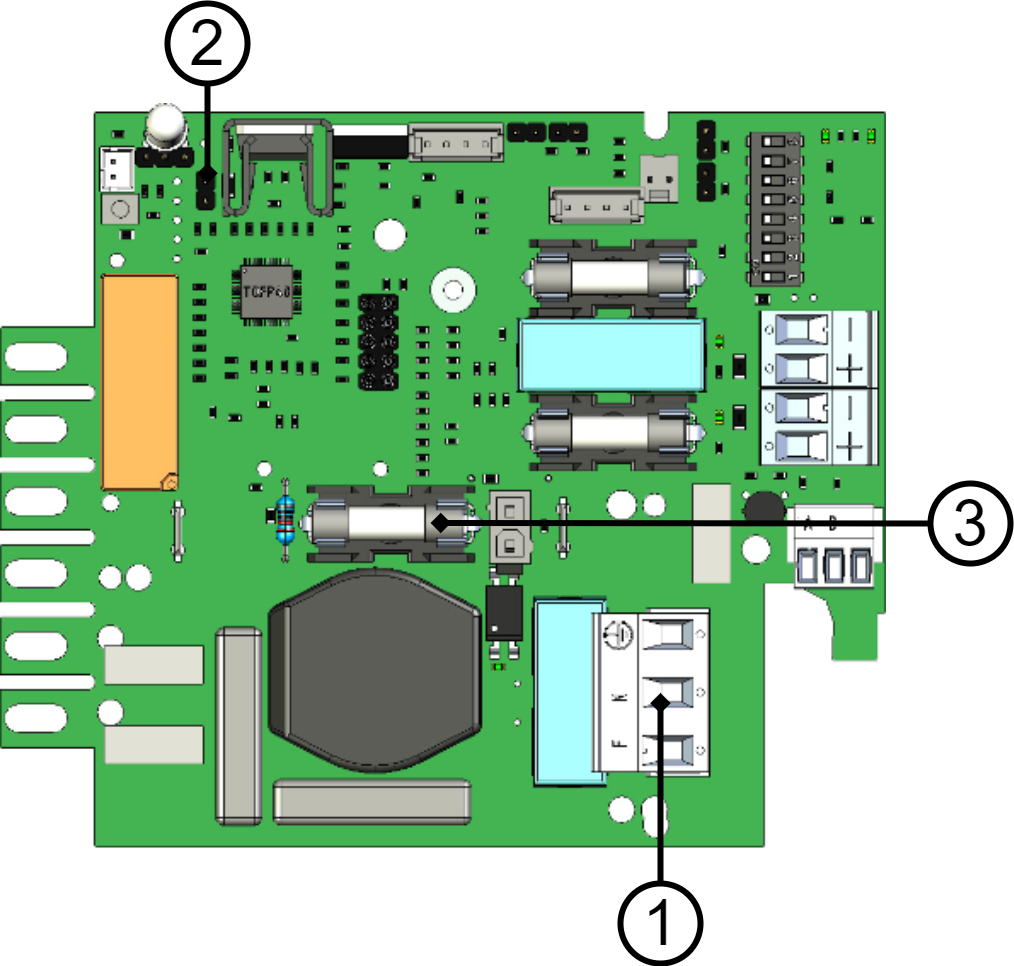
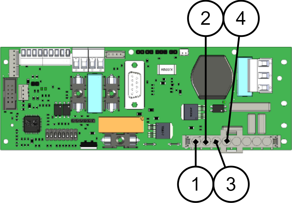
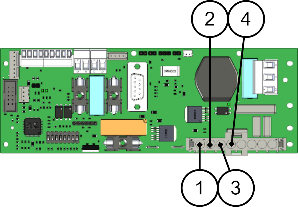
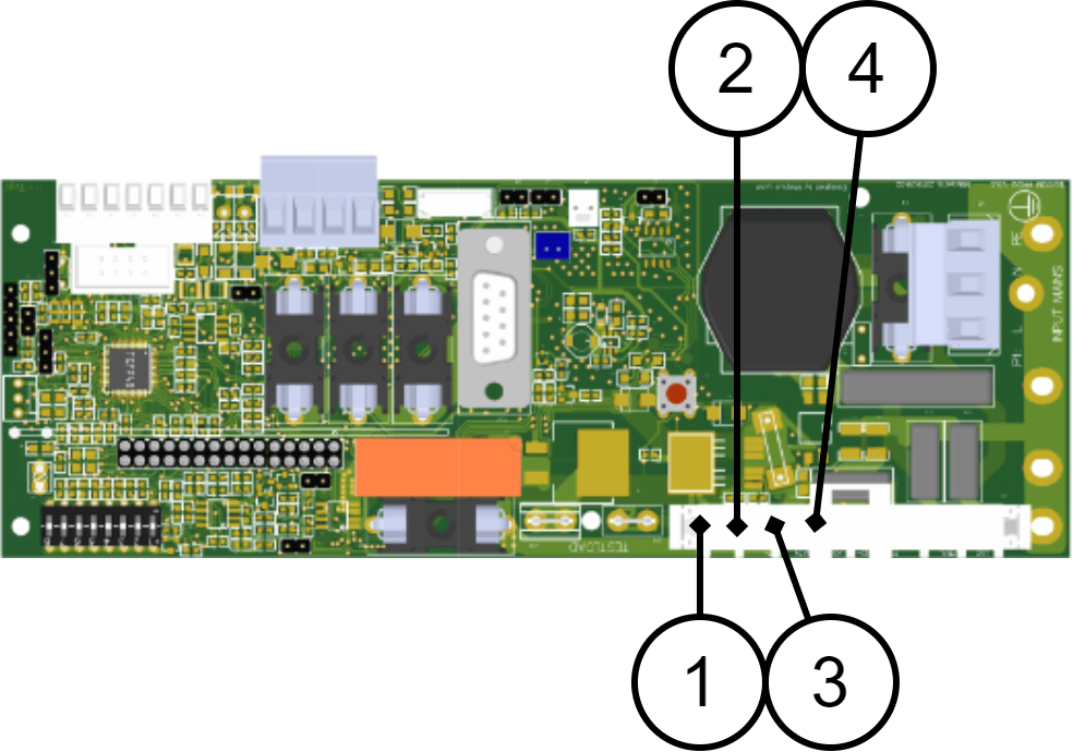
Measure output voltage P1:1 and P1:2 (1). If the voltage is lower than 12 V / 24.0 V or if the voltage is lower than 13 V / 26.0 V and does not rise at least 0.1 V after 5 minutes, proceed to the next step.
Reset “J11” (2) (quick short circuit and system restarts). If the indicator LED flashes quickly orange (cell short circuit or disconnected batteries or very low batteries), call our support and order upgrade dongle. Have serial number available.
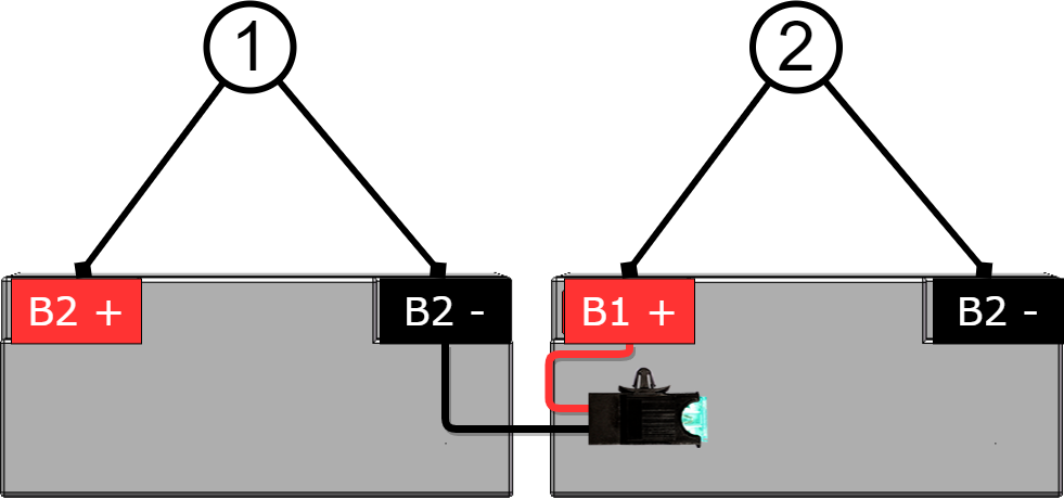
Measure the battery voltage on each battery with the battery fuse (3) disconnected and note the different pole voltages of the batteries. Battery replacement may be necessary but upgrading may not be necessary.
Slow green flashes: Tamper alarm - Alarm from tamper contact

Status means: Alarm from the tamper contact.
Remedy: Check whether damage has been done to the device or that the tamper switch is correctly adjusted. If the battery box is connected, the yellow cable in the battery backup connector must be cut and in all battery boxes except the last battery box. Adjust tamper contact if necessary.
Troubleshooting: Keep the tamper switch pressed, then the tamper alarm should stop, if not check the jumpers on the motherboard.
Check jumpers on motherboard, see below.
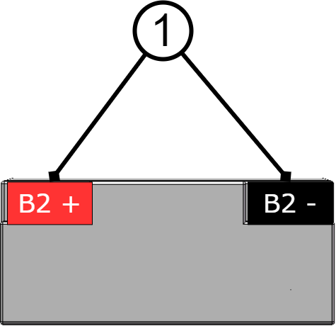
If there is a battery box (FLX-M and FLX-L), the yellow cable must BE ENTIRE on the last/bottom Battery Box (Last part in the chain) but cut on the other connectors.
If necessary, adjust all tamper contacts, see instructions below. Close all hatches. The tamper alarm ceases and the Green indicator LED is constantly green=OK.
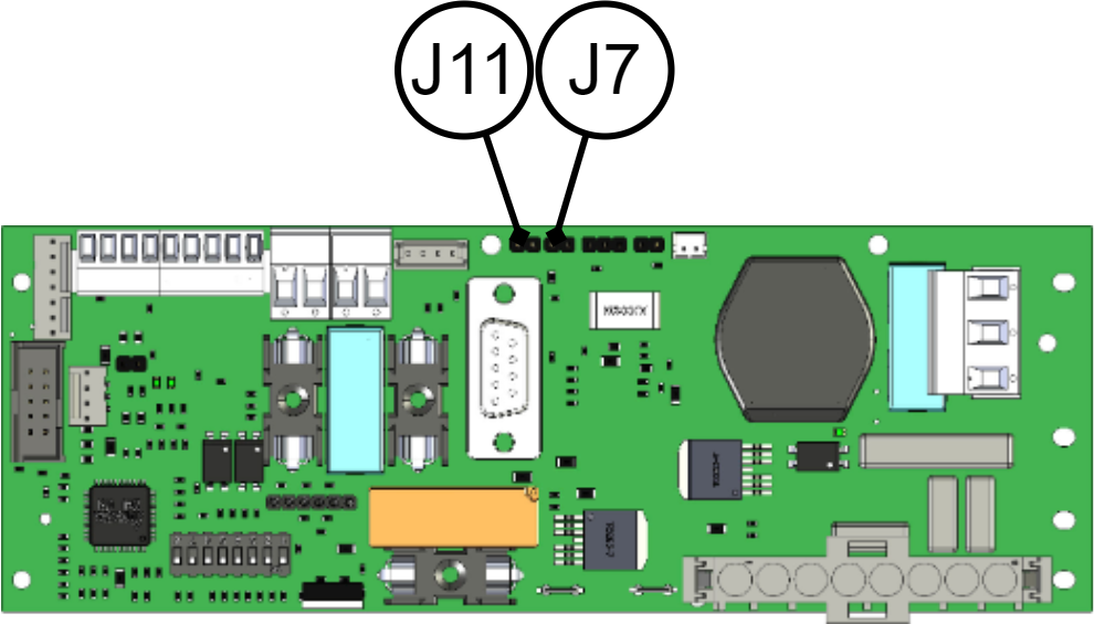
The J7 + J11 connectors must be in or jumpered.
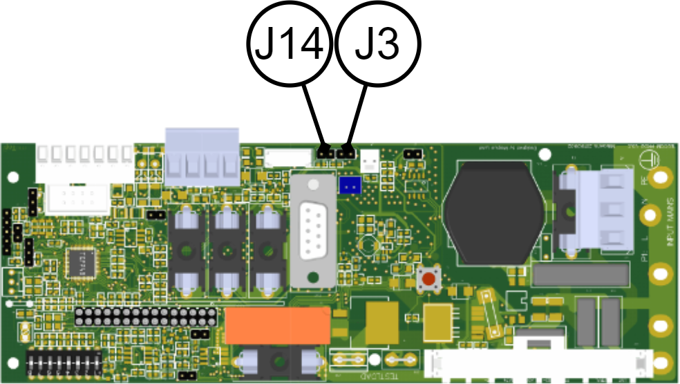
The J3 + J14 connectors must be in or jumpered.
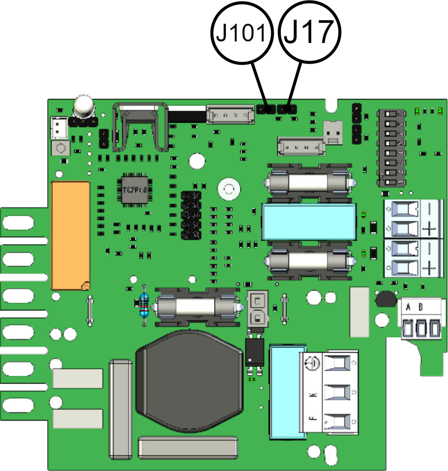
The J17+J101 connectors must be in or jumpered.
Tamper switch adjustment
Adjustment of tamper switch
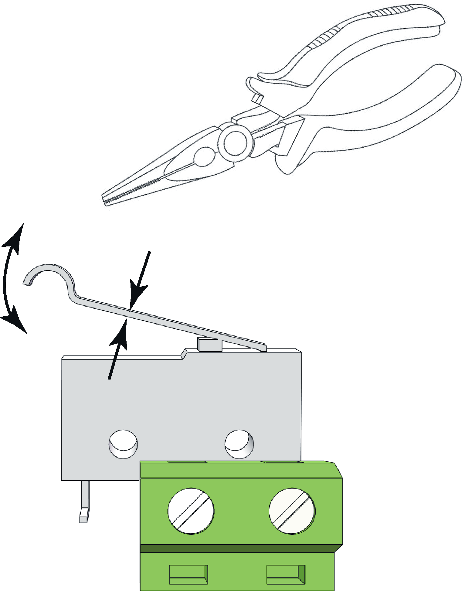 |
The tamper switch lever must be in the closed position when the cabinet door is closed. If the alarm goes off ("tamper alarm"), the lever may needs to be adjusted.
The lever is adjusted by the following steps:
Pinch with pliers in the middle of the lever.
Carefully adjust the lever in the desired direction (up / down).
Check by closing the door. A click is heard when the contact is closed.
Notice
Tamper switch will not give an alarm when closed and locked the door.
Fast green flashes: Mains failure - alarm for mains failure

Status means: Interruption of power supply (230 V) to the device.
Action: Fix network interruption. Check that the terminal for 230 V is seated properly and that there is mains voltage up to the jackable terminal.
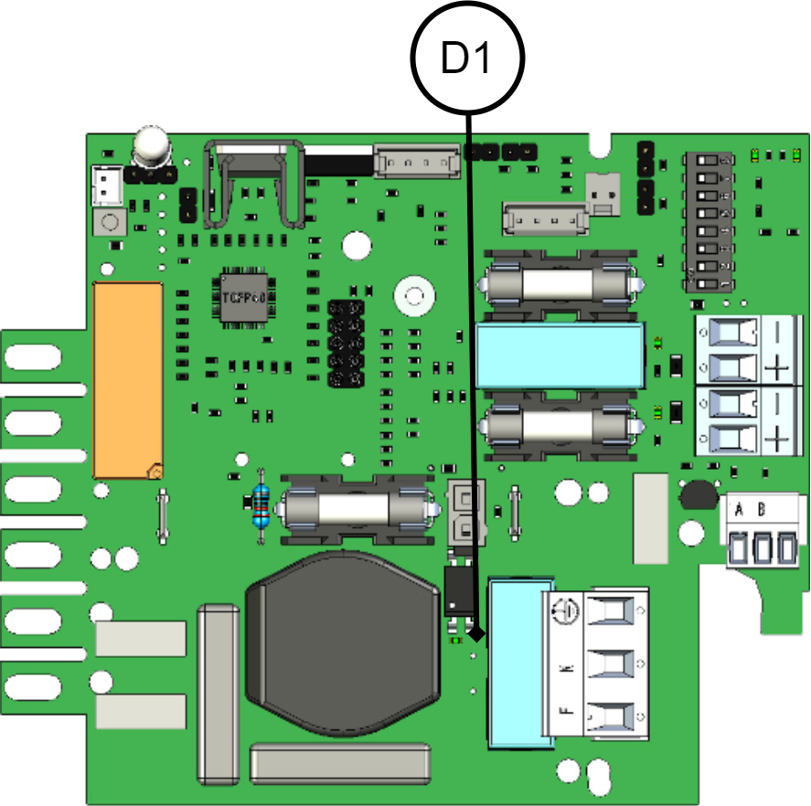
Troubleshooting: Check if the mains voltage diode lights up with a solid green light on the circuit board.
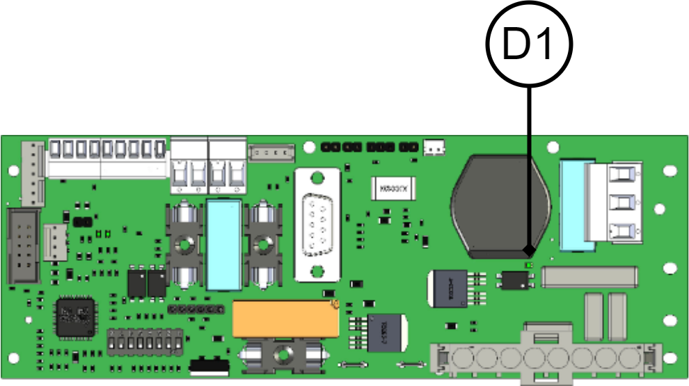
D1 LED should light up if 230 VAC is connected.
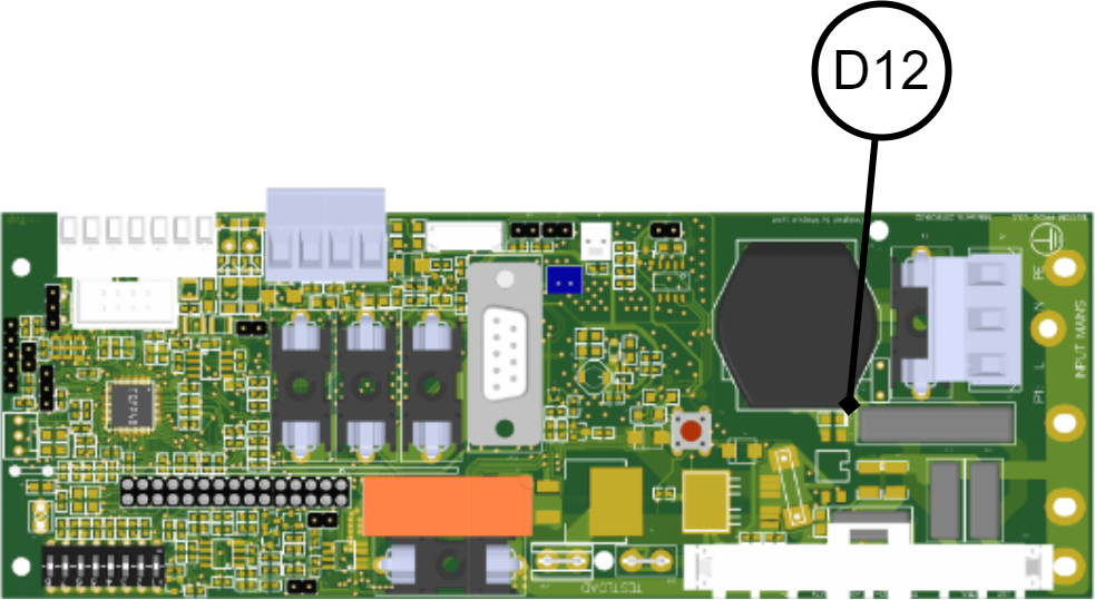
D12 LED should light if 230 VAC is connected.
D1 LED should light up if 230 VAC is connected.
If the LED lights up green, there is mains voltage to the card and the processor registers it, otherwise measure with a multimeter AC voltage measurement on mains terminal P1:1 "Line"(Phase) and P1:2 "N"(Zero) that 230 VAC is present.
Solid yellow light: Low Battery - Low battery voltage

Status means: Battery voltage is low below 12 V / 24 V when the device is powered by batteries.
Action: Normal operating condition during long-term power failure and subsequent recharging of the batteries.
Troubleshooting: Troubleshooting does not need to be done when batteries are being charged.
Slow yellow flashes: Aged Battery - Aged batteries

Status means: Batteries need to be replaced, so that backup operating time can be safely maintained. Weekly battery capacity tests are carried out, over a built-in test load, to establish that the batteries are not outdated.
Check: That the temperature is not too high, above 25 °C, in the surroundings.
That any fan works/spins. It should be considered to also change the fan in connection with changing the battery.
Remedy: Replace all batteries with equivalent batteries in terms of life and capacity. Possibly replace the fan as well (its lifespan is 6-8 years depending on the ambient temperature).
After battery replacement, the alarm resets itself, may take up to a week. With reset, the alarm can be cleared immediately.
For battery replacement: read under section battery replacement in the installation manual
S1, Dip-switch 8 is set to OFF-ON-OFF. Only the alarm is deactivated, a new test takes place automatically within a week.
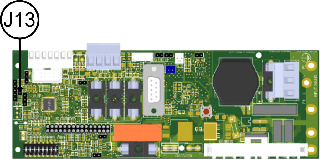
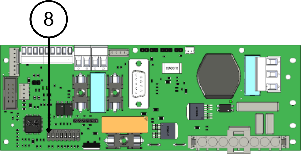
Restarting the device software is done by jumpering J13. New battery test takes place automatically after one week.
Important
If batteries are not sufficiently charged when installed, an alarm may be given again during testing. Wait a week until batteries are charged and test is done again.
Battery test (dip 8)
To do a battery test, dip 8 needs to change position and five seconds need to pass before the test is initiated.
If dip 8 in original position is on OFF then switch dip 8 to: ON (wait 5 seconds) and then switch back to OFF.
If dip 8 in original position is on ON then switch dip 8 to: OFF (wait 5 seconds) and then switch back to ON.
This activates the battery test after 3-8 seconds. The battery test lasts for about 6 seconds and then the LED flashes yellow quickly. Aged battery alarms may be indicated while the battery test is being performed.
Only reset dip 8 when the test is complete.
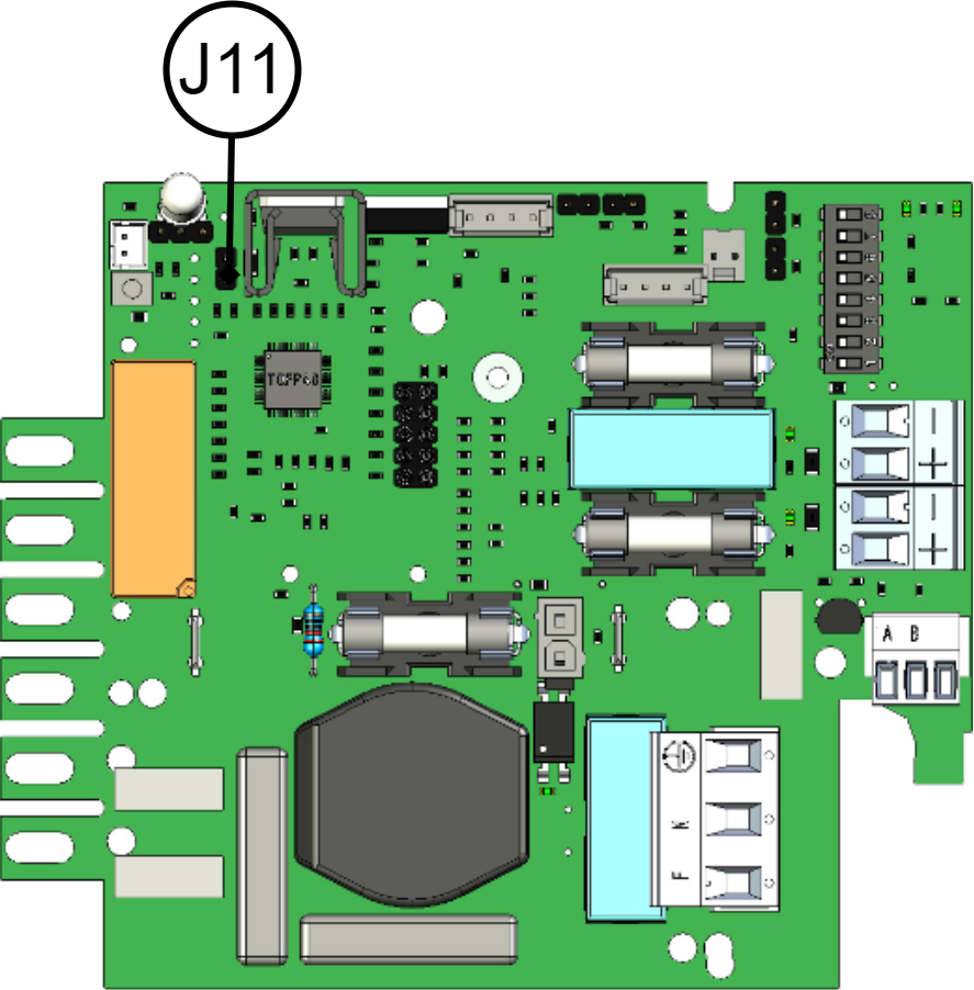
Restarting the device software is done by jumpering J11. New battery test takes place automatically after one week.
Battery test (dip 8)
To do a battery test, dip 8 needs to change position and five seconds need to pass before the test is initiated.
If dip 8 in original position is on OFF then switch dip 8 to: ON (wait 5 seconds) and then switch back to OFF.
If dip 8 in original position is on ON then switch dip 8 to: OFF (wait 5 seconds) and then switch back to ON.
This activates the battery test after 3-8 seconds. The battery test lasts for about 6 seconds and then the LED flashes yellow quickly. Aged battery alarms may be indicated while the battery test is being performed.
Only reset dip 8 when the test is complete.
Important
If batteries are not sufficiently charged when installed, an alarm may be given again during testing. Wait a week until batteries are charged and test is done again.
Troubleshooting: Measure battery voltage in mains operation across the battery terminals. 13.65 V / 27.3 V.
Disconnect all battery fuses in battery backup and battery boxes. Measure the voltage of each individual battery and record the value. The voltage must be over 13.3 V / 26.6 V on each battery. The differences between batteries must be less than 0.3 V.
Fast yellow flashes: Disconnected batteries / battery cell shortage - Disconnected batteries / battery short circuit.

Status means: Batteries are disconnected or battery fuse between the batteries switched off or cell failure in batteries which led to a short circuit in the battery.
Action: Check that all battery terminals are tightened and all battery fuses (one per battery box and in the main unit) are switched on.
Battery Troubleshooting:
1. Measure battery voltage with multimeter and with mains voltage and battery fuse switched on; note the total voltage value. Measure the battery terminal voltage, it should be higher than 12 V / 24 V (13.65 V / 27.3 V).
2. Measure battery terminal voltage to confirm that the batteries do not have a cell short circuit. Disconnect all battery fuses in battery backup and battery boxes. Measure the voltage of each individual battery and record the value. The voltage must be over 13.3 V / 26.6 V on each battery. The differences between batteries must be less than 0.3 V.
Important
The voltage of each individual battery should be above 13.3 V (unless there was a longer mains outage earlier in the day).
Important
Note that the difference between the batteries should not be more than 0.3 V. Replace all batteries if the difference is more than 0.3 V.
Solid red light: Over or under voltage / charger fault - Over or under voltage or charger fault.

Status means: Problem with the power supply, it is providing too much or too little voltage or has received an internal error.
Action and Troubleshooting: Disconnect all batteries by disconnecting all battery fuses. Measure across the plus and minus poles of the power supply unit to check unit voltage. In case of larger deviation (more than -0.5 V and +0.2 V), measure the load with a current clamp / Ammeter, set to DC current and note that the current does not continuously exceed 80% of the rated capacity. If over 100% of the measurement capacity, install larger battery backups or distribute the load on more battery backups. Otherwise, in case of minor deviations, the voltage of the power supply can be adjusted via potentiometer to setpoint 13.65 V / 27.3 V.
After measurement: Reset battery fuses. Disconnect the mains voltage to verify that the battery backup works in battery operation.
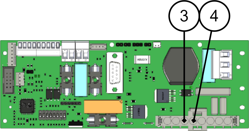
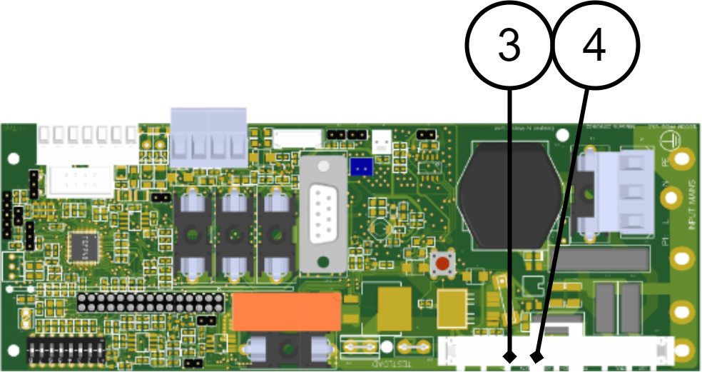
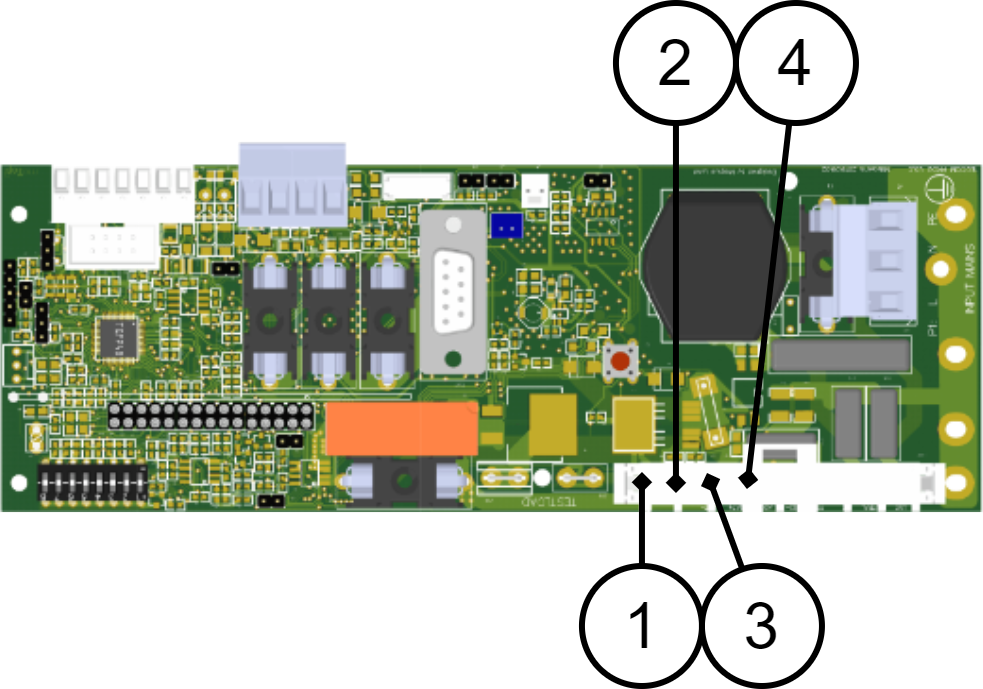
Multimeter red plus+ cable on Header1 no. 3 on the circuit board and Black minus cable to Header1 no. 4. Make sure you make contact with the connector pins.
Multimeter red plus+ cable on Header1 no. 3 on the circuit board and Black minus cable to Header1 no. 4. Make sure you make contact with the connector pins.
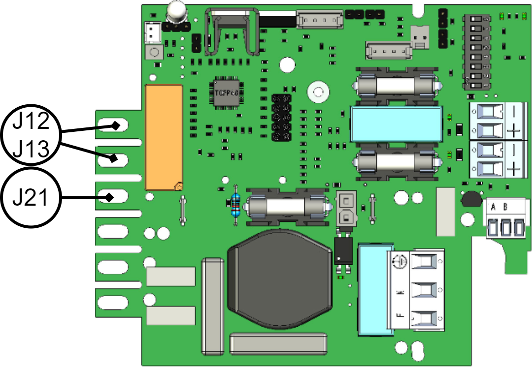
Multimeter red plus+ cable on J12/J13 on circuit board black minus cable to J21.
Slow red flashes: Low system Voltage - Low system voltage.

Status means: The voltage from the battery backup is too low, (below 12.0V / 24.0V), which is a natural operating condition when recharging after a long-term power failure.
Action: If there has not been a longer power outage recently. Check that the load does not exceed the rated power of the battery backup and that the power supply is set correctly.
Troubleshooting: Measure the load with a current clamp / Ammeter, set to DC current and note that the current does not continuously exceed 80% of the rated capacity. If over 100% of the measurement capacity, install larger battery backups or distribute the load on more battery backups.
Disconnect all batteries by disconnecting all battery fuses.
Multimeter red plus+ cable on Header1 no. 3 on the circuit board and Black minus cable to Header1 no. 4. Make sure you make contact with the connector pins. The voltage must be 13.65 V / 27.3 V (-0.5 V/+0.2 V). Otherwise, the power supply should be adjusted or (if the power supply is older than 5 years) replaced.
Multimeter red plus+ cable on Header1 no. 3 on the circuit board and Black minus cable to Header1 no. 4. Make sure you make contact with the connector pins. The voltage must be 13.65 V / 27.3 V (-0.5 V/+0.2 V). Otherwise, the power supply should be adjusted or (if the power supply is older than 5 years) replaced.
Multimeter red plus+ cable to J12/J13 on the circuit board and Black minus cable to J21. The voltage must be 13.65 V / 27.3 V (-0.5 V/+0.2 V). Otherwise, the power supply should be adjusted or (if the power supply is older than 5 years) replaced.
Fast red flashes: Blown load / battery fuse blown - Load fuse has tripped / battery fuse has tripped.

Status means: Fuse for load or battery has tripped.
Action: Replace the fuse / switch on the circuit breaker or contacts on the circuit board become loose.
Troubleshooting: Check that battery fuses are intact or switched on. Check that the load fuses are intact, if the load fuses have tripped, check that there is no short circuit in the load. Green indicator diode lights up at each load output if the fuse is intact and there is voltage out.
Total alarm for circuit board fuses, alarm from fuses on any load card and battery fuses from battery boxes.
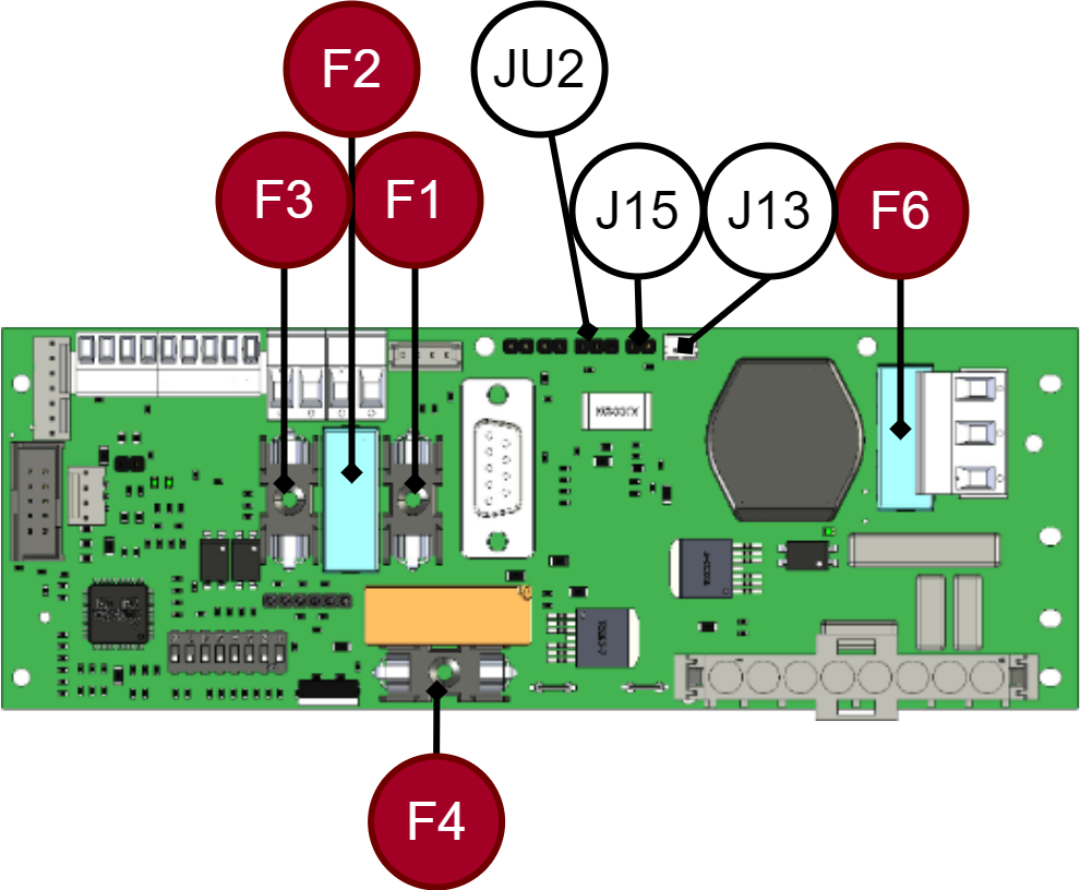
1. Check load fuses F1, F2, F3, indicator diode at load outputs lights up green if fuses are intact and voltage is present. and battery fuse F4 that they are intact. Check all battery fuses in battery backup and any battery boxes.
2. JU2. Cable for battery fuses from external battery boxes on terminal "JU2", (NO). there is no battery box connected, no cable is connected to JU2. JU2 Does not need to be bridged. Pull this cable and if the alarm stops, then there is a fault with this cable or in non-activated battery fuses in battery box(es).
2.1. If alarm stops. Put the cable back and check that the automatic fuses in the battery box(es) are switched on.
3. J15. Check if external load cards are connected to J15 (NC). Loosen the cable, put a jumper so that the alarm from J15 cannot be given. If the alarm disappears when the jumper is inserted, the fault lies in the external load distribution board. Troubleshoot as below.
3.1 If the load card is not connected, J15 must be jumpered.
3.2 If load cards are connected to J13, pull this cable to check whether the fault is in cable or external load card. No jumper is needed. If the alarm disappears, the fault lies in the external load distribution board. Troubleshoot as below.
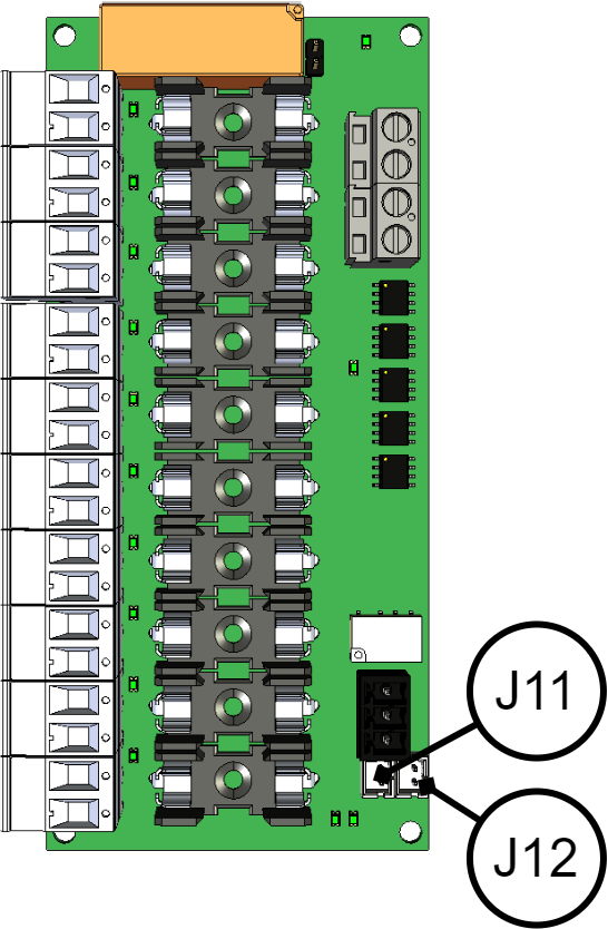
4. J13. Load distribution cards can be connected to J13 alt (J15) and further to load cards: 2 OUT LOAD J1 or J2 or 5 Output module J6 or J7 or 10 Output module J11 or J12 “.
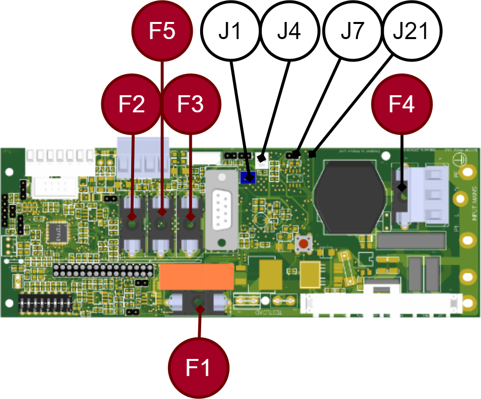
Check load fuses F2, F3, F5 and battery fuse F1 that they are intact. Check all battery fuses in battery backup and any battery boxes.
Check if external load distribution boards are connected to J7 (NC) and J21 (NC).
If the load distribution card is not connected, J7 and J21 must be jumpered.
Load distribution cards can be connected to J1 and further to load cards: 2 OUT LOAD "J1 or J2" or 5 Output module "J6 " or "J7 " or 10 Output module "J11 " or "J12 ".
Cable for battery fuses from external battery boxes on terminal "J4", (NO). there is no battery box connected, nothing should be connected to JU2. Does not need to be bridged.
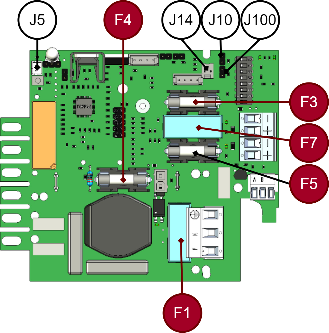
Check load fuses F5, F7, F3 and Battery fuse F4 on the motherboard. Check all battery fuses in battery backup and any battery boxes.
Cable for battery fuses from external battery boxes on terminal "J14", (NO). there is no battery box connected, nothing should be connected to J14. Does not need to be bridged.
Check if external load distribution boards are connected with cable to: J10 and J100 (NC) or jumper and/or cable to J5 and to output board 2OUT LOAD "J1 or J2" or 5Output module "J6 " or "J7 " or J10 Output module "J11 " or "J12".
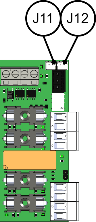
J11 and J12 are connection from motherboard. A green LED lights up at each load output when the fuse is complete and voltage is present at the load output. Total LED lights up red if the fuse is tripped.
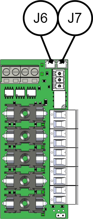
J6 and J7 are connection from motherboard. A green LED lights up at each load output when the fuse is complete and voltage is present at the load output. Total LED lights up red if the fuse is tripped.
J11 and J12 are connection from motherboard. A green LED lights up at each load output when the fuse is complete and voltage is present at the load output. Total LED lights up red if the fuse is tripped.
Black / off: Deep discharge protection (system shutdown) - Deep discharge protection is activated. (The device has turned off.)

Status means: When the system is in operation: If the indicator diode is off, deep discharge protection (below 10.5 V / 21 V) has taken effect and the power supply does not supply sufficient voltage to the load.
Action: Check that mains voltage is present and that the power supply unit supplies voltage.
Troubleshooting: 1. Check that the unit has mains voltage, check that the mains voltage diode is solid green on the circuit board.
D1 LED should light up if 230 VAC is connected.
D12 LED should light up if 230 VAC is connected.
D1 LED should light up if 230 VAC is connected.
If the LED lights up green, there is mains voltage to the card and the processor registers it, otherwise measure with a multimeter AC voltage measurement on mains terminal P1:1 "Line"(Phase) and P1:2 "N"(Zero) that 230 VAC is present.
2. Measure across the plus and minus poles of the power supply unit to check that the unit voltage is greater than (10.5V) / 21V. Otherwise call support for power supply replacement.
Multimeter red plus+ cable to Header1 No. 3 on the circuit board and Black minus cable to Header1 No. 4. Make sure you make contact with the connector pins.
Multimeter red plus+ cable to Header1 No. 3 on the circuit board and Black minus cable to Header1 No. 4. Make sure you make contact with the connector pins.

Multimeter red plus+ cable on J12/J13 on the circuit board's "fork" into "American terminal" further into the power supply and Black minus cable to J21.
Reset all battery fuses. Disconnect mains voltage to verify that the battery backup works in battery operation!
About translation of this document
User manual and other documents are in the original language in Swedish. Other languages may be machine translated and/or not reviewed, errors may occur.