Before troubleshooting - check this!
The troubleshooting below assumes that the battery backup is sized correctly. Measure the current if there is suspicion that the device is loaded with more than 80% of the capacity of the battery backup.
PRO1 note on indication when charging batteries
While charging batteries, the motherboard stops charging the batteries every 10 seconds to perform a battery test. (read more about this under the fast orange tab) This means that the load on the power supply is greatly reduced for a short while. Some power supplies have a current-controlled fan. When the load decreases for a short time, the fan speed will decrease at the same rate. This can cause a strange decrease in the fan noise from the battery backup every 10 seconds and voltage can gasp, especially at high load.
Tamper contact - troubleshooting
Disconnect the incoming tamper contact/s to the motherboard and jumper them. Older motherboards sometimes have one tamper input instead of two.
If the device stops alarming for tampering after bridging the Tamper inputs. Check that you get a connection to the wiring from the switches. If not, check the cable and switches, if necessary, replace the switch and cable.
Does the battery backup continue to alarm after bridging Tamper inputs? If yes: Then the LED may be the wrong way round or defective. Continued troubleshooting for slow red and slow orange.
If none of the above fixes the problem. Contact support for motherboard replacement.
Tamper contact - troubleshooting PRO1
Disconnect the incoming tamper contact/s to the motherboard and jumper them. Older motherboards sometimes have one tamper input instead of two.
If the device stops alarming for tampering after bridging the Tamper inputs. Check that you get a connection to the wiring from the switches. If not, check the cable and switches, if necessary, replace the switch and cable.
Does the battery backup continue to alarm after bridging Tamper inputs? If yes: Then the LED may be the wrong way round or defective. Continued troubleshooting for slow red and slow orange.
If none of the above fixes the problem. Contact support for motherboard replacement.
Newer card with two inputs, on the left. Older card with one input, on the right.
Power failure alarm - troubleshooting
Check that the incoming FAS is approx. 220v-240V and approx. 50Hz.
Check fuse for incoming phase on motherboard. The fuse is mounted next to the incoming FAS in fuse location F6. As standard, the fuse is Ceramic T2.5 in units up to 24V 10A. T4.0 in units larger than 24V 15A. It is possible to mount a fuse smaller than 2.5A/4.0A, but not larger.
If the battery backup continues, alarm fast green: Measure output load voltage. If the output voltage is above 27.00V, then the LED may be reversed or defective. Continue troubleshooting fast red and troubleshooting fast orange.
If the above troubleshooting fails, contact support for motherboard replacement.
Low battery voltage - troubleshooting
Solid orange is not an error but information. The rectifier informs that the voltage across the batteries is low. The battery voltage may be low if the battery backup is in battery operation, or if the battery backup has recently been in battery operation. By default, the circuit board should alarm for low battery voltage at 24.00 V or lower. This value can be adjusted via communication, provided that the subordinate system supports this.
Check that the voltage across load and battery does not differ by more than 0.5v and that the voltage increases by at least 0.02v within 3 minutes.
Replace the battery backup if this does not happen.
Solid orange should return to solid green within 72 hours.
Replace the battery backup if this does not happen.
Aged battery - troubleshooting
Important
check that there is no distance between the battery terminals and the ring cable lugs/female pins.
Batteries and cables must be properly tightened. There must not be washers between the poles and ring shoes. This will probably generate a false battery error alarm during installation or later.
Are the correct size batteries installed? In Milleteknik's battery backups, the battery test is adapted to the enclosure type. If smaller batteries are installed than intended in the current enclosure type, the alarm aged battery will be presented earlier than intended. It is the enclosure that determines which power resistors are installed. The power resistors determine the load the batteries will receive during the high-current load test. (Set battery capacity does not affect the orange alarms or any alarm on the panel at all).
Check that there is no corrosion between the contact surfaces. If there is corrosion, the contact surfaces need to be cleaned.
Do a battery check, see Checking the battery and battery charge.
The battery test can generate the alarm Aged battery:PRO 1
48 hours after start-up/restart, the battery backup makes a high-current load of the batteries.
After that, high-current loading of the batteries is done weekly (7 days).
If the battery voltage drops below the Aged Battery limit during the battery test, the battery backup will alarm for Aged Battery.
Battery test is performed even if there are no batteries installed.
Example: Say you have started the battery backup without batteries.
The battery backup alarms for disconnected battery/cell short circuit = Fast orange.
The battery backup is without batteries for over 48 hours.
The battery backup does its battery test 48 hours from start-up, which will show a negative result, which triggers the alarm Aged battery = Slow orange.
The battery backup keeps flashing fast orange, because fast orange has higher priority is slow orange.
You install new batteries and the battery backup stops flashing orange quickly and shows the next priority alarm on the list. Which is slowly orange = Aged battery.
To reset the old battery alarm, you can either wait up to 72 hours, or do a software reset by setting dipswitch 8 to ON – OFF – ON. The software reset will not break voltage to the load.
Checking the battery and battery charge
The test requires a multimeter with at least two decimal places (00,01) and connected load.
The battery backup must be in operation.
Measure across the battery terminals on the 24V side. The voltage must be between 27.00 V – 27.50 V
Measure each battery separately. Still in operation. The voltage must not differ by more than 0.5V. Example: 13.75 and 13.50 are accepted. While 13.30 and 13.90 are failed.
Disconnect the incoming mains and wait for about 2 minutes.
Within 2 minutes the voltage should have dropped to 24.00 V – 27.00 V depending on the size of the battery and load. The voltage should stop after approx. 5 minutes of battery operation and increase by 0.01 V - 0.10 V. Example: The voltage drops to 25.30v and increases to 25.35v. Which is Approved. This is called stabilizing the batteries. Example 2: Battery voltage continues to drop without staying in voltage = Failed. Replace batteries.
Measure voltage across each battery separately. Still in battery operation. The voltage should not differ by more than 0.5 V. Otherwise, replace the batteries.
Measure the difference between battery voltage and load voltage in battery operation. The difference should not be more than 1.00 V If the difference is more than 1.00 V, it may mean cold soldering on the motherboard or that the wiring has not been clamped properly. Replace the battery backup. This is a very rare problem.
Disconnected battery, cell short - troubleshooting
The battery test that the battery backup does that can trigger the battery disconnected alarm (fast orange) is done every 10 seconds in mains operation. When the test is performed, the motherboard connects the load directly across the batteries for a very short time and measures how much the battery voltage drops. If the battery voltage drops below the limit value, the alarm disconnected battery / fast orange is triggered.
Be careful and check that there is no distance between the battery terminals and the rings/female pins. Batteries and cabling must be tight. This is super important!
Example: There must not be washers between the poles and ring shoes. This will probably generate a false battery fault alarm. Maybe not at installation, but at a later time.
Are the correct size batteries installed? In Milleteknik's battery backups, the battery test is adapted to the enclosure type. If smaller batteries are installed than intended in the current enclosure type, there is a risk of the device giving false alarms for disconnected batteries.
Check that there is no corrosion between the contact surfaces. If there is corrosion. Remove corrosion with a wire brush.
Do one battery check.
PRO1: If the above does not fix the problem and the firmware on the motherboard is older than 4.33.4. the error can be fixed with a firmware update. Because firmware 4.33.4 has a lowered alarm limit value for the alarm: Fast amber indication = Disconnected batteries / battery cell shortage. a. If it is "only" a device that gives false alarms for disconnected batteries, it is recommended to replace the motherboard instead of doing a firmware update. b. If there are several devices that are false alarms, you could start by doing a firmware update. All motherboards named TEQ-COM PRO can be updated with a firmware update. Contact support for more information.
Over or under voltage - troubleshooting
Charger failure means that the battery backup has determined that the power supply/AC/DC converter is defective.
The alarm can only be triggered in mains operation and if the system voltage is below 26.7 V and is stationary or falling. Or above 27.8 V (overvoltage) The alarm will not be triggered if the voltage is below 26.7 V and increases in voltage. If the voltage is above 27.8 V, the charging of the batteries will be cut off.
If the diode in the lid flashes red slowly when the lid is open and glows solid red when the lid is closed. Then the LED is the wrong way round and needs to be reversed.
Measure the voltage directly from the power supply. a. If the voltage is below 27.00 V or above 27.50 V and the alarm is solid red, replace the power supply. b. If the voltage is between 27.00 – 27.50v and gives a solid red alarm. Replace motherboard
Low system voltage - troubleshooting
The alarm is triggered if the voltage is below 24.00 V in mains operation. (The alarm must not be triggered in battery operation).
The alarm can be triggered after a power failure and when the battery backup has not recharged the batteries above 24.00 V.
If the diode in the lid flashes red slowly when the lid is open and lights up solid red when the lid is closed, then the LED is the wrong way round and needs to be reversed.
Check that the voltage is increasing across the batteries. If the voltage is stagnant or drops. Go to the troubleshooting for Over or under voltage - troubleshooting and follow the instruction.
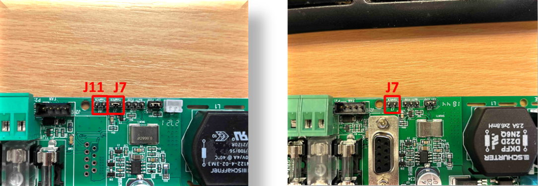
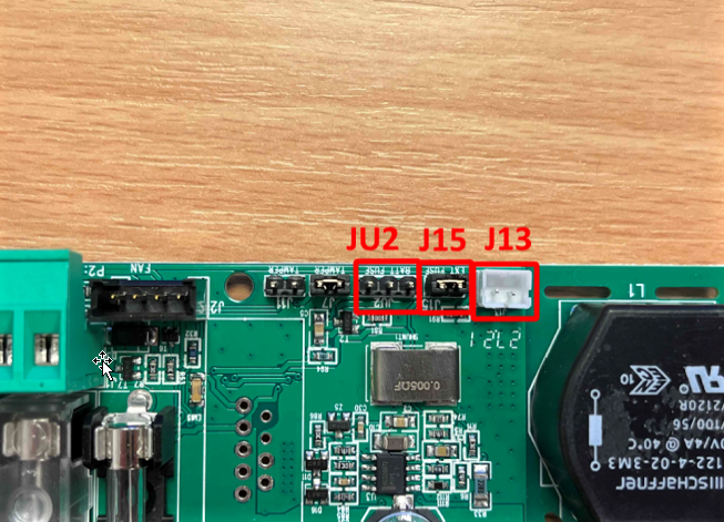
Tripped load fuse fault, fuse fault - troubleshooting: PRO1
Fast red is alarm for fuse failure. Both load fuses and battery fuses. The alarm can be triggered if one or more fuses fail on the motherboard. (but not fuse for incoming FAS).
One of the inputs JU2, J15 and J13 sounds an alarm.
JU2(NO, Normally Open) This is a three-pin connector. If one of the outer legs is grounded/shorted to the middle leg, this will generate an alarm. JU2 is usually connected to the circuit breaker that connects the batteries in series and also the circuit breakers found in some battery boxes.
J15 (NC, Normally Closed) This is a two-pin connector. Which is sometimes connected to circuit breakers for the load or load distribution board. On devices manufactured in 2022 or later, this connector is jumpered/shorted.
The J13 (5v high/low signal) connector can only be used for circuit boards with the same connector. These contacts can be found on optional cards such as 5 output module or 10 output module.
Check that all fuses are intact and switched on.
Disconnect JU2 (which is Normally Open). a. If the device is starting, the green light is on. Check the automatic fuses at the batteries. b. Ohm measure the connector that plugs into the motherboard. The contact must be open.
Disconnect J13 (The connector is not on all circuit boards and it is not always plugged in) If the device starts to light up green = check that the alarm from the fuse board(s) is working. check the alarm from the fuse board by measuring Ohms on the relay output of the fuse board before and after a fuse is disconnected. The relay output must switch in the event of a fuse failure. If the fuse board relay output does not switch = Replace the fuse board.
Disconnect any contact from J15 and ensure that J15 is jumpered.
If the battery back light starts to glow green. Check that the alarm from the fuse card/s is Normally Closed. check the alarm from the fuse board by measuring Ohms on the relay output from the fuse board before and after a fuse is disconnected. If the fuse board relay output does not switch = Replace the fuse board.
Tip
Sometimes the contacts on the pin inputs JU2 and J15 have come loose during transport or during installation. When the connectors are reassembled, they may have moved. This will trigger the fuse failure alarm. Try switching connectors JU2 and J15. After the action. Check that the battery backup alarms for fuse failure when a fuse is blown.
Tip
If the green LED in the panel is defective, the alarm is actually quickly orange. If the above tests do not work. Try troubleshooting for Disconnected battery, cell short - troubleshooting.
About translation of this document
User manual and other documents are in the original language in Swedish. Other languages may be machine translated and/or not reviewed, errors may occur.