About Sinus UPS from Milleteknik
The SIN inverter is an Off-line UPS that steps in and replaces the supply from the mains in the event of a mains failure, until the mains returns (or the batteries are completely discharged). SIN inverters are designed with the latest switching technology and microprocessor monitoring, for: Highest efficiency and operational reliability, providing long life for both electronics and batteries. Well protected with isolation switch, battery circuit breaker, protection against overtemperature, overload, short circuit. Complete self-test including advanced battery test. The units are installation and service friendly: Compact volume. External wall brackets for installation without having to open the electrical cabinet for quick installation. Modular structure. All electronics on cassette for easy servicing or upgrading.
The UPS is charged with a built-in power supply and is powered further by batteries in the event of a power failure.
Safety - read this first
The unit must be installed by a qualified person.
It is the installer's responsibility that the system is suitable for intended use.
Documents accompanying the system must be kept in its immediate vicinity.
The system should not be connected to the mains during installation.
All information is subject to change.
Danger
Dangerously high voltage.
Wait one (1) minute after power has been disconnected from the unit.
About translation of this document
User manual and other documents are in the original language in Swedish. Other languages are machine translated and not reviewed, errors may occur.
Component overview
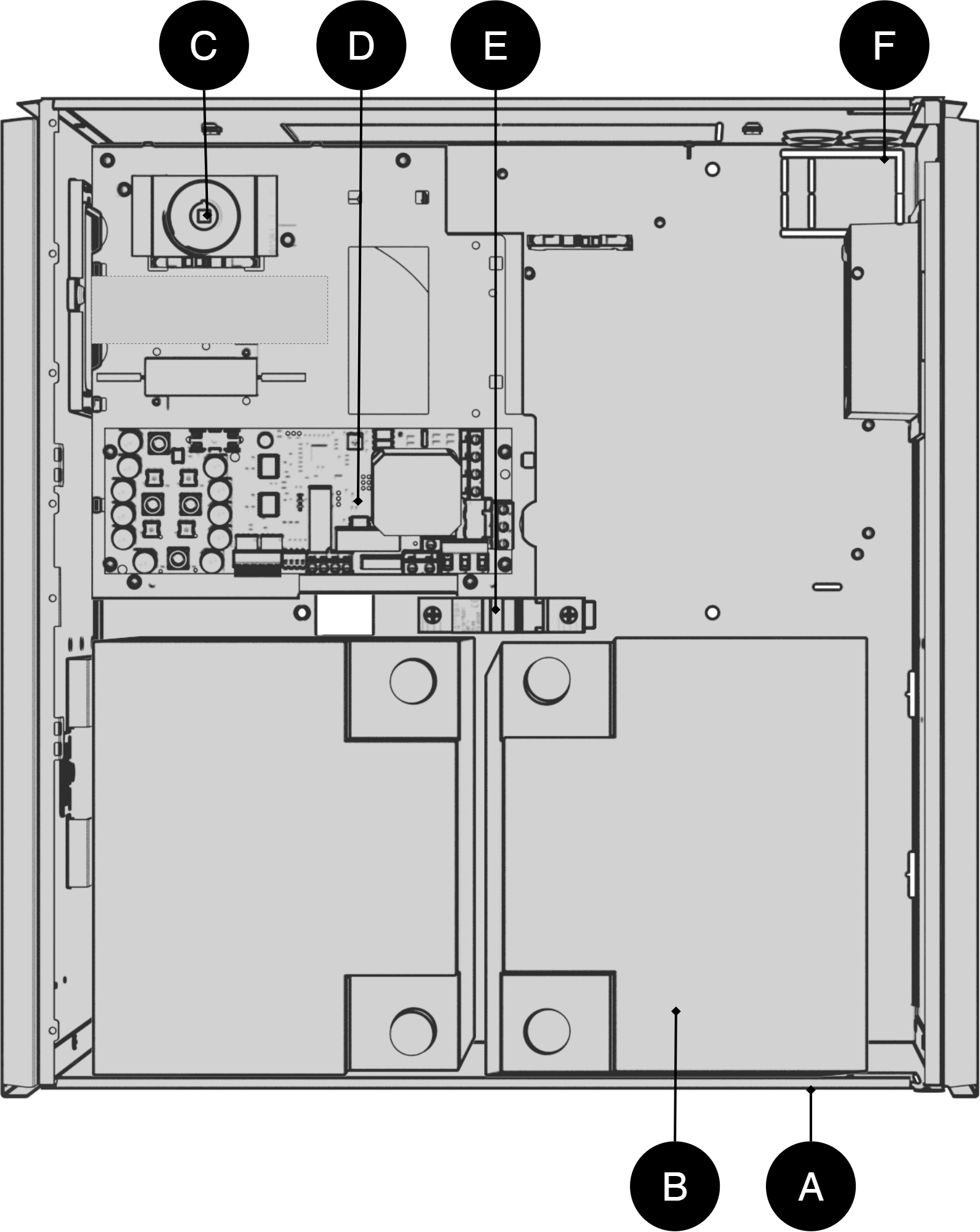
Batteries should be placed as in the picture.
Letter | Explanation |
|---|---|
A | Cabinet in powder-coated sheet metal with bracket for reversible bracket for wall mounting or 19 "rack |
B | Batteries |
C | Isolation switch |
D | Motherboard |
E | Battery fuse |
F | Cable entries |
Enclosures
Bracket
Brackets are used so that the unit can be mounted on a wall or in a 19 "rack.
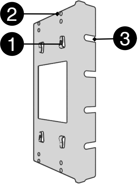
Nr | Explanation |
|---|---|
1 | Clip in bracket that secures the bracket to the housing. |
2 | Holes for screws - can be used to secure the bracket in the housing. |
3 | The brackets is screwed to a wall or 19 "rack. |
Mounting FLX L
The unit can be mounted in a 19" rack or on a wall. The supplied brackets can be attached in two ways: When mounting on a wall, the brackets must sit backwards, against the wall. When mounting in a 19" rack, the console must sit at the front of the unit.
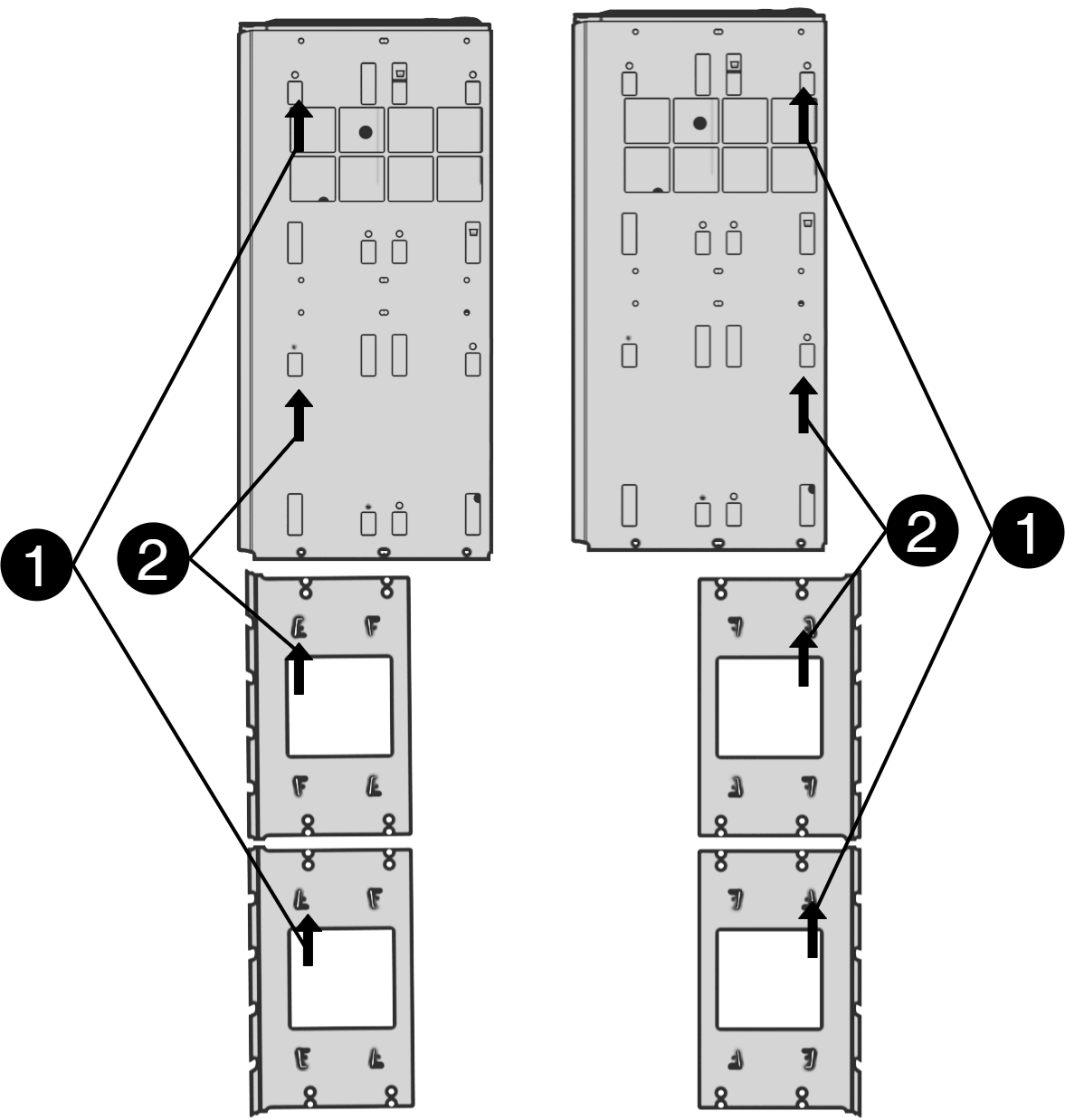
Left bracket facing the front for mounting in a 19 "rack.
Right bracket facing the back for wall mounting.
Nr | Explanation |
|---|---|
1 | Start by attaching the top bracket. |
2 | Attach the lower bracket. |
Important
Leave 100 mm free around the air vents.
Mounting
Use the appropriate screw for mounting on a wall or in a 19" rack. Screws for mounting on a wall or in a rack are not included.
Connection 230 V
In: Battery connection
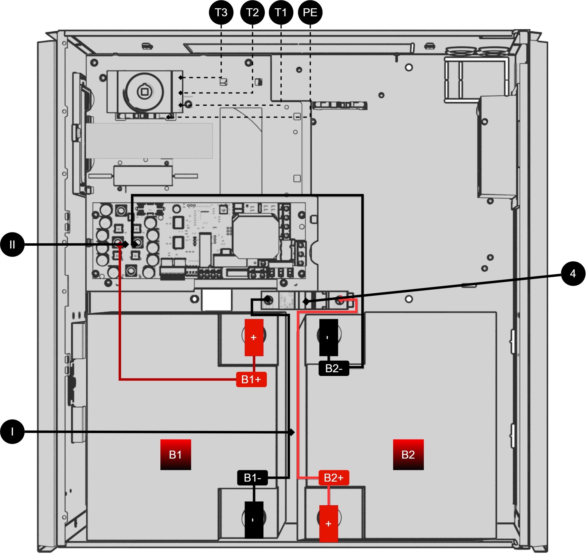
No / letter | Explanation |
|---|---|
I, III | Battery wiring for automatic fuse. |
II | Battery wiring from motherboard. |
4 | Battery fuse (automatic fuse) |
T3 | Internal emergency stop. |
T2 | Phase, incoming mains. |
T1 | Zero mains, incoming. |
PE | Incoming protective earth. |
Connect as the picture shows; - possibly incoming controlled - incoming mains phase to terminal T2 on isolation switch, - incoming zero to terminal T1. - protective ground to terminal "PE".
B1, B2 | Explanation |
|---|---|
B1+ | + from circuit board to battery |
B1- | - from fuse to battery. |
B2+ | + from fuse to battery. |
B2- | - from circuit board to battery. |
Load disconnector incoming mains (in: 230 V)
For maximum safety, always disconnect from the mains before installation and service. Connect a load disconnector (circuit breaker) to the incoming cable from the mains. Place it easily accessible and label it clearly. With a load disconnector installed, incoming voltage can be easily interrupted during service and function tests.
Out: 230 V
Output phase/load to PICTO marked 9 on circuit board overview and 4 on circuit board. Output phase/load to (EMERGENCY LIGHT) marked 8 on circuit board overview and 5 on circuit board, (only energized in case of mains failure). Output zero, to ZERO, labeled 7 on circuit board overview and 6 on circuit board. Protective earth, PE, marked 6 on circuit board overview and 7 on circuit board.
Description motherboard: MiniSinus
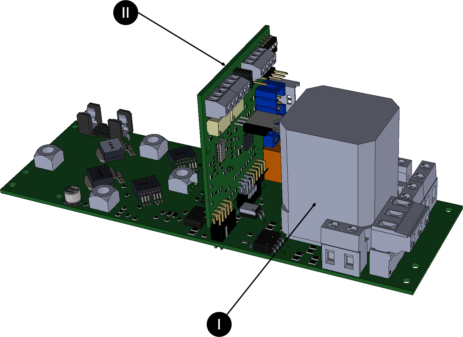
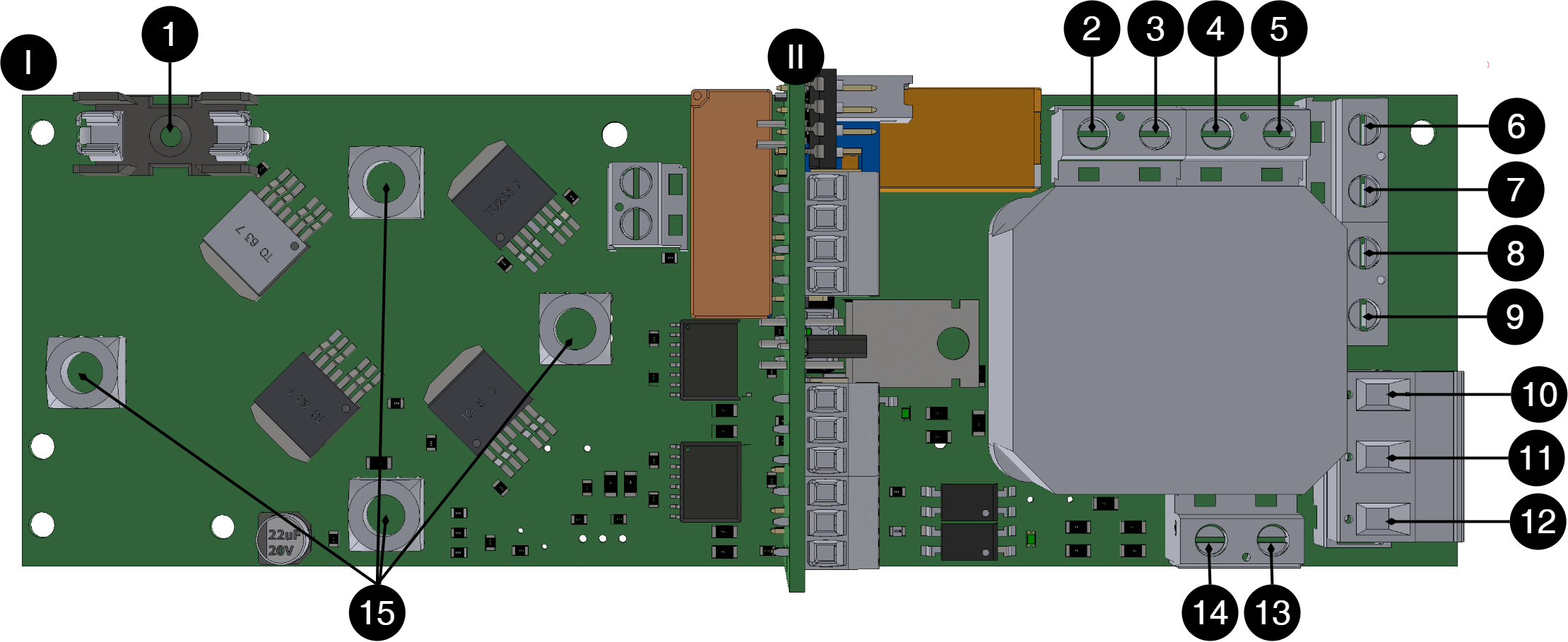
No | On circuit board | Explanation |
|---|---|---|
1 | F1 | Fuse from power supply, 24 VDC for battery charging. |
2 | N Test load | Disconnects from the factory. |
3 | L Test load | |
4 | N UPS | |
5 | L UPS | |
6 | PE | Protective ground, Output |
7 | Zero / Neutral | Zero, Output |
8 | (LED 0/230 V) | (Outgoing load, 230 V. Connection to emergency light/indicator light. Only voltage in case of mains failure) |
9 | PICTO 230 V / 230 V | Output load, 230 V. Connection to pictogram. Always phase voltage |
10 | LINE | Mains voltage connection: 230 V In (PHAS in) |
11 | NEUTRAL | Connection mains voltage: 230 V Zero |
12 | PE | Connection mains voltage: 230 V Protective earth, PE |
13 | (PHASE 230 V) | Disconnects from the factory. |
14 | (ZERO 230 V) | |
15 | J5, J11, J31, J33 |
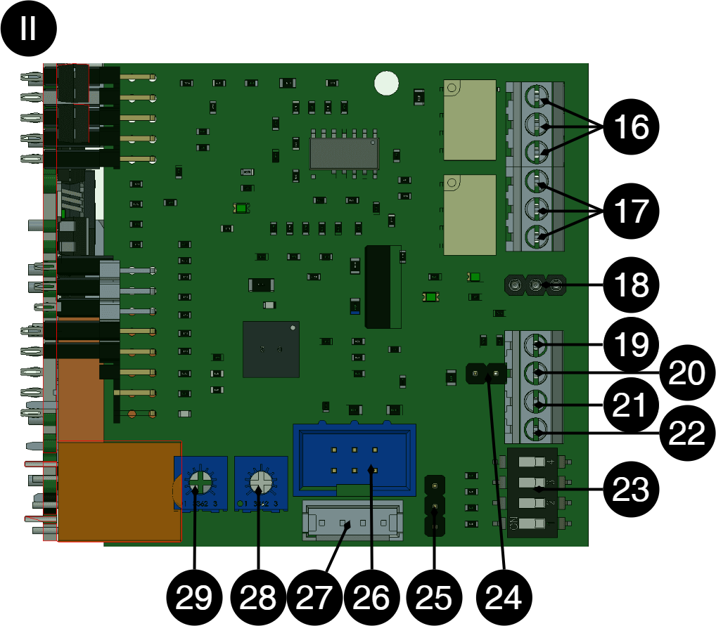
No | On circuit board | Explanation |
|---|---|---|
16 | 10 9 8 | Self-diagnosis, NC Self-diagnosis, COM Self-diagnosis, NO |
17 | 7 6 5 | Mains failure alarm, NC Power failure alarm, COM Mains failure alarm, NO |
18 | Summer | Connection to buzzer |
19 | 4 | +5V |
20 | 3 | B+ (RS-485, upcoming feature) |
21 | 2 | A- (RS-485, upcoming function) |
22 | 1 | GND |
23 | S1 | Dip switch - must not be changed |
24 | J16 | Not used, factory connected |
25 | J8 | |
26 | J4 | |
27 | J24 | |
28 | P3 | Not available |
29 | P4 |
Alarm connection
Self-test and alarm for mains failure
P1:1-3, incorrect charging voltage (over/undervoltage), aged battery - when the battery should be replaced, or non-functioning inverter to circuit board terminal P1:1-3. Alarm - contact NO and CO. Mains failure: Connect the mains failure alarm P1:1-3, "MAINS ALARM", an alarm is given immediately in the event of a mains failure.
Connect total alarm for self-test
Incorrect charging voltage (over/undervoltage), aged battery - when the battery should be replaced, or non-functioning inverter to 16. Alarm - contact NO and CO. Normal (no alarm)
Connect alarm for mains failure
Alarm - contact NO and CO. Connection takes place on a horizontal circuit board, 17.
Commissioning - how to start the unit
After connection, start-up must take place in the following steps:
Step | Explanation |
|---|---|
1 | Turn the isolation switch to "0" and open the cabinet. |
2 | Connect the input and output cable, alarm and switch on the circuit breaker for the battery pack. |
3 | Close the electrical cabinet and turn the isolation switch to "1". |
4 | Connect to the mains. |
5 | The system starts up automatically. LED indication on the cabinet door flashes until it lights up steady GREEN. The UPS is commissioned and activated. The load is fed directly from the mains in normal mode and from the batteries via the inverter in battery operation. Switching time is typically 20 ms. |
6 | Temporarily disconnect mains voltage via mains switch or central fuse to test that the UPS is working (connected load continues to be powered in battery mode). |
7 | Reconnect to mains voltage. |
Features inverter
The SINUS UPS inverter is an Off-line UPS that steps in and replaces the supply from the mains in the event of a mains failure, until the mains is restored (or the batteries are completely discharged). The switching time is about 20ms. The inverter replaces the grid's sinusoidal voltage with a current-limited sinusoidal voltage.
The inverter is an Off-line UPS that steps in and replaces the supply from the mains in the event of a mains failure, until the mains returns (or the batteries are completely discharged). The switching time is typically 20 ms. The inverter replaces the grid's sinusoidal voltage with a current-limited sinusoidal voltage.
Note
In the event of a mains failure, the inverter starts up and draws approximately 10 W of energy even when unloaded (idle power).
Batteries UPS
The batteries are valve-regulated maintenance-free 10-12 year batteries especially suitable for UPS operation with high short-term power consumption. Automatic fuse for battery protects against possible internal short circuit. The batteries are protected from overload by the inverter through electronic current limitation. The batteries are protected against harmful deep discharge so that all current consumption ceases when the battery voltage falls below a critical value (19 V). Only returning mains and thereby power from battery chargers overrides deep discharge protection. The batteries are also protected against "boiling-gassing" due to overcharging, by being disconnected from the charging current.
Battery charger UPS
The batteries are charged to 27.3V final voltage under current limitation to achieve optimal service life at room temperature +20°C—+25°C. The charger is overcurrent and short circuit protected and also protects the batteries from overcharging/high charging current.
Protection UPS standard 62040-1-1
Electronic current limitation and overtemperature protection as well as automatic shutdown in case of heavy overload or short circuit after 3-5 seconds according to UPS STANDARD EN62040-1-1. The inverter is thus short-circuit protected.
Warning
However, mains voltage must not be connected to the output of the inverter, 13-14 on circuit board overview,
Self-test system
As standard, the unit includes a self-test system (STS) that continuously monitors all functions in the system.
The self-test has three different parts:
1. Battery charging. Alarm is given in case of over or maintenance voltage charging. Undervoltage is only indicated if the charger for charged batteries does not provide the correct charging voltage. No false alarms when the batteries are recharged after a power outage, as the battery voltage is naturally low. Alarms are indicated by a yellow LED on the front panel at the same time as a self-diagnosis alarm is set. In case of overvoltage, the charge is disconnected from the batteries to prevent them from starting to "boil-gas". In case of overvoltage, the front panel LED shows red at the same time as a self-diagnosis alarm is set.
2. Alarm for aged battery. The capacity or aging of the batteries is tested regularly (every week). If tests show that the current battery capacity has fallen below 80% of the original rated capacity, an alarm is given to warn that the batteries need to be replaced. The reliability of the reserve operation is hereby tested in accordance with the established dimensioning requirements for the desired reserve operation time in battery operation. Batteries that have lost 20% of their capacity or more accelerate aging. They should therefore be replaced. This limit is defined as the life of the battery. In the event of an alarm for an aged battery, yellow flashes are given on the LED on the front of the cabinet at the same time as a self-diagnosis alarm is set.
3. The inverter test runs over an internal test load corresponding to the rated power, at the same time as a battery aging test. (Every week). This ensures that the output voltage is sufficient in UPS operation under load. In the event of an inverter fault, red flashes are given on the LED on the front panel (possibly additional flashes in case of several alarms) at the same time as a self-diagnosis alarm is set.
Care instructions UPS
The unit is maintenance-free when installed in a room temperature indoor environment +15°C—+25°C. However, the batteries should be changed after 10-12 years to maintain high guaranteed safety. In the extended temperature range +5°C—+15°C/+25°C—+30°C, the batteries will age twice as fast. Further colder or warmer ambient temperature means that reliability is at risk.
Battery replacement UPS
Step | Explanation |
|---|---|
1 | Turn the isolation switch to "0" and open the cabinet. Input phase voltage is interrupted. The inverter is put into active stop mode (the drive voltage to the electronics is disconnected. |
2 | For safety's sake, also disconnect the mains voltage. |
3 | Disconnect the batteries by setting the battery automatic fuse to "0 – OFF". |
4 | Disconnect battery cables and replace batteries. Be careful not to short-circuit the batteries! Remove the upper battery and then bring the lower battery up past the battery's automatic fuse. Note and be careful with the orientation of the batteries regarding battery poles +/- and battery cable assembly! |
5 | Connect the battery cables to the new batteries with the correct polarity. Be careful not to short-circuit batteries! |
6 | Set battery circuit breakers to "1 – ON". |
7 | Close the electrical cabinet and turn the isolation switch to "1". |
8 | Reconnect the mains if it has been disconnected. |
9 | The SelfTestSystem starts up automatically. LED indication on the cabinet door flashes until it lights up steady GREEN. The UPS is commissioned and activated. The load is fed directly from the mains in normal mode and from the batteries via the inverter in battery operation. Switching time is 20 ms. |
10 | Temporarily disconnect mains voltage to test that the UPS is working (connected load continues to be powered in battery mode). |
11 | Reconnect to mains voltage. |
Dimensioning UPS
Dimension the connected load so that it is, in total, as large as the inverter's maximum rated power (W), preferably less to partly obtain safety margins, and partly to compensate for losses in connections/cabling and the load which means greater actual power consumption from the inverter than the specified rated power of the load. Take temporary starting power into account, so that it does not exceed the specified maximum - short-term - starting power (VA) of the inverter. Back-up load operation should take place within one hour of the grid failure occurring, as the inverter consumes power at idle, which gradually drains the batteries.
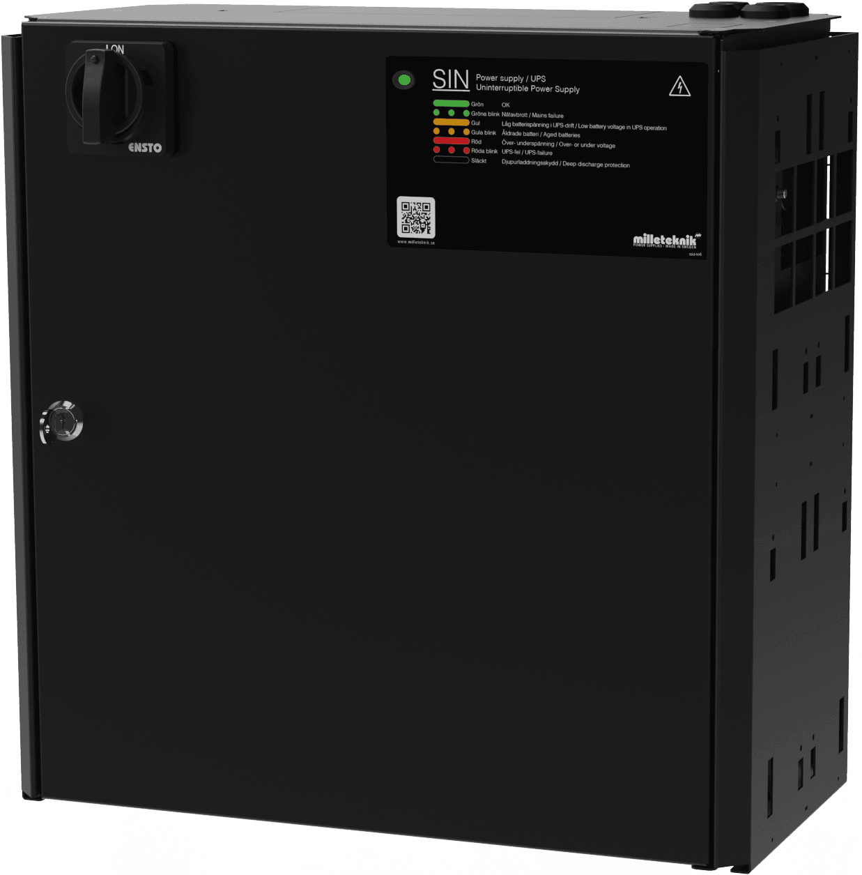
Front panel and status indicators
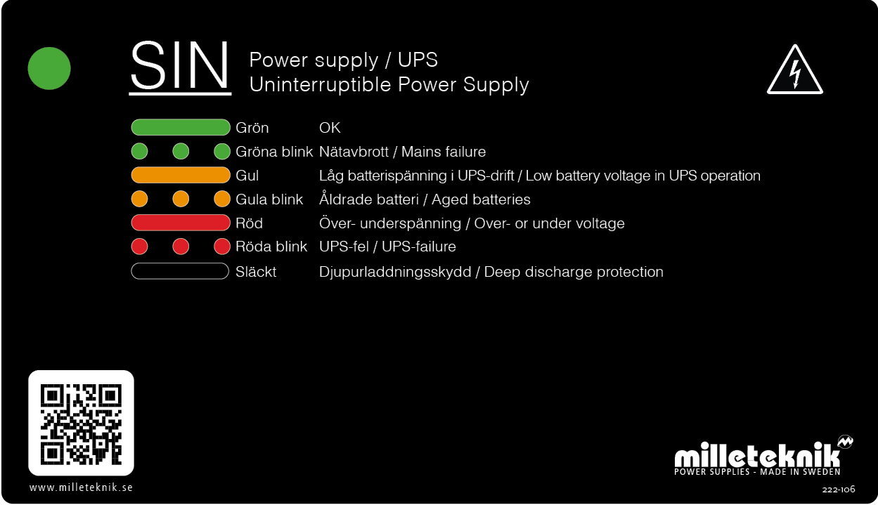
Panel for UPS with Minisinus in FLX M and FLX L housing
Indicator diode | Text | Explanation |
|---|---|---|
Green, solid glow | Okay | The device is working normally |
Green blinks | Power outage | 230 V mains failure |
Yellow, solid glow | Low battery voltage in UPS operation | |
Yellow flashes | Aged battery | Battery needs to be replaced |
Red, solid light | Over-undervoltage | Voltage fault |
Red flashes | UPS ERROR | Over temperature, over current or feedback error. |
Black / off | Deep discharge protection | Deep discharge protection has kicked in |
FAQ UPS
Control measures in case of alarm UPS - Battery charge, over or under voltage
Over or under voltage is indicated if the device, when the batteries are charged, does not provide the correct charging voltage. Alarms are indicated by flashing on the front panel at the same time as a total alarm is set.
Action in case of alarm: Check charging voltage. Measure voltage to 27.3 V. At two-pole power supply terminal, (red plus, black minus cable).
Control measures in the event of an alarm UPS - Alarm for aged battery
The batteries' capacity and aging are tested weekly. If the test shows that the battery capacity has dropped below 60% - 80% of the battery's original capacity, an alarm is given for an aged battery
Action in case of alarm: Replace batteries.
Control measures in case of UPS alarm - UPS fault / inverter fault
In the event of an inverter fault, the LED on the front panel flashes at the same time as a total alarm is set.
Action in case of alarm:
Check fuses in the unit.
Check with a multimeter that the device provides charging output, (230 V ) in mains operation and in battery operation.
Batteries have sufficient voltage, (27 V). Measure the battery terminals.
Control measures in case of alarm UPS - Overvoltage, too high charging current
If the charging voltage in normal operation exceeds 27.9 V, the charging is disconnected.
Check with a multimeter that the device's charge does not exceed 27.9 V.
Contact support for further assistance with adjusting the voltage of the power supply unit.
Test load in UPS (part of self-test system)
The unit is tested weekly against an internal test load. This is to check that the output voltage is sufficient for UPS operation and thus that the batteries are not aged.
Are alarms given when batteries are recharged after a power outage?
No alarms are given when the batteries are charged after a mains failure.
Technical facts alarm: Incorrect charging voltage
Alarm for incorrect charging voltage is given if the charger's voltage falls below 26.5 V.
Undervoltage may be natural after prolonged discharge, UPS operation. To ensure that the power supply does not break during recharging, a test is made every 45 minutes that the charging voltage is correct.
Alarms for incorrect charging voltage/broken power supply are displayed on the panel and via potential-free relay switching.
Technical facts alarm: Overvoltage
If the charging voltage in normal operation exceeds 27.9 V, the charging is disconnected. An alarm is also given on potential-free relay switching.
Technology facts alarm: Aged battery
Every week, batteries are tested with a high, predetermined and short-term load current across internal load resistors that correspond to the batteries' rated power. Current battery capacity is measured. The microprocessor takes a "fingerprint" of the current state of the battery in the load test. The value taken is then compared with the programmed battery value. In tests that give an indication of between 20% - 40% of the original battery capacity, an alarm for an aged battery is given. Alarm is also given on potential-free relay switching/Sum-alarm.
Technology facts alarm: Inverter test
Every week the unit is tested with internal load. If the unit's inverter does not provide sufficient output voltage, an alarm is given. Alarm is also given on potential-free relay switching.
SIN
SIN - UPS Product sheet / technical data
Technical specifications
These technical specifications are subject to change without notice.
SINUS UPS name, article number and e-number
Name | Article number | E-number |
|---|---|---|
SINUS UPS 600W FLX L | FL01U0021FP006 | 52 136 60 |
Maximum rated power
Maximum rated power | Continuous effect |
|---|---|
SIN 600W FLX L | 600 W |
ABOUT UPS
The UPS are designed with the latest switch technology and microprocessor monitoring, for maximum efficiency and reliability, providing long life for both electronics and batteries. UPS is well protected with isolation switch, battery circuit breaker, protection against overtemperature, overload, short circuit.
Fixed installation
The product is intended for fixed installation. The battery backup must be installed by a qualified installer.
Areas of use
SINUS UPS is mostly used for camera surveillance, PoE switches and other security systems. Sinus UPS is also used for gates and gate control of smaller and larger industrial and garage doors.
Camera surveillance,
PoE switches and other security systems.
Gate and door control of smaller and larger industrial and garage doors.
The product is not intended for emergency lighting control
Ignition phase is missing. Retrofitting of the ignition phase is not possible.
Regulations and certifications
Requirements that the product meets
EMC: | EMC Directive 2014 / 30EU |
Electricity: | Low voltage directive: 2014/35 / EU EN 62368-1 |
CE: | CE directive according to: 765/2008 |
Emission: | EN61000-6-: 2001 EN55022: 1998: -A1: 2000, A2: 2003 Klass B, EN61000-3-2: 2001 |
Immunity: | EN61000-6-2:2005, EN61000-4-2, -3, 4, -5, -6, -11 |


Circuit boards - Technical data
Technical data: CEO 3
Info | Explanation |
|---|---|
Article title | CEO3 |
Product description | CEO 3 is the next generation circuit board for simpler battery backups. Advanced functions that were not previously possible in simpler battery backups are now available as standard. CEO 3 is a reliable heart in simpler battery backups with fewer components than before, which reduces the environmental impact. |
Measure | 120 x 55 mm x 52 mm |
Voltage form | 1-phase sine |
Fuses | See table: Fuses |
Fuse on output | 24 V |
Outputs | Output: four load outputs 1-4 which are prioritized load outlets. (= always voltage). |
Insurance | Load output: + secured. |
Indication | Display showing operating status, alarms and faults. Operating indication: one indication diode per load output +/-. Solid green light = normal operation. |
230 V voltage in
Voltage | Explanation / comment |
|---|---|
Voltage in: | 230V -15%, + 20% in mains operation. |
Mains power: | charger max 0.4A + load. |
230 V output voltage
Voltage OUT | Explanation / comment |
|---|---|
Voltage out: | 230 V - 10% in battery operation. |
Voltage form: | Single-phase sine voltage. |
Efficiency, approx: | 90% |
Idle power, approx: | 10 W |
Battery charge
I / O according to DIN 41773 Current limitation.
Protection
Type of protection | Explanation |
|---|---|
Current limitation, electronic: | Type 300% of rated capacity. |
Short-circuit protection: | Shutdown within 5 sec in case of heavy overload / short circuit according to UPS EN62040-1-1 standard. Automatic restart when mains voltage returns. |
Depth discharge protection: | When the battery terminal voltage is less than 19 V. |
Overcharge protection: | Disconnection of charging voltage during overcharging. |
Automatic fuse: | Batteries are secured. |
Insulation switch: | When opening an electrical cabinet, the knob on the cabinet door must be set to "0", thus disconnecting the incoming phase and UPS emergency stops. |
Optional: Ground fault circuit breaker: | Can be installed on output (extra protection option according to EN62040-1-1). |
Fuses Minisinus v8
On circuit boards | Fuse | Explanation |
|---|---|---|
F1 | T16A | Battery fuse |
Self-test
Type of self-test | Explanation |
|---|---|
Battery charge | Continuous monitoring of battery chargers. |
Battery aging | Automatic test loading of batteries under high, short-term discharge current to detect battery aging. The test compares measured battery capacity with programmed values to give an alarm when the battery has lost 20% - 40% capacity of new value and should be replaced. |
Inverters | Test load of UPS (corresponding rated power over internal test load) to check function and sufficient output voltage. |
Alarm
All alarms occur on potential-free relay switching.
Alarm type | Explanation |
|---|---|
Power outage alarm | Alarm in case of network interruption adjustable time delay from direct to 10 h (3s, 3, 15, 30m, 1, 2, 4, 10h). |
Sum Alarm, Self-Test: | Incorrect charging voltage (over- or under-voltage), aged battery that should be replaced or a malfunctioning inverter. |
Technical data enclosures
Enclosures - Technical Data FLX L
Info | Explanation |
|---|---|
Name | FLX L |
Enclosure class | IP 32 |
Measure | Height: 444 mm, width 438 mm, depth 212 mm |
Height units | 10 HE |
Mounting | Wall or 19 "rack |
Ambient temperature | + 5 ° C - + 40 ° C. For best battery life: + 15 ° C to + 25 ° C. |
Environment | Environmental class 1, indoors. 20% ~ 90% relative humidity |
Material | Powder coated sheet |
Color | Black |
Cable entries, number | 4 |
Batteries that fit | 2 st 12 V 45 Ah |
Place for fan | Yes |
Batteries - recommended, not included
Batteries are not included they are sold separately
Batteries are sold separately.
45 Ah, 12 V AGM battery
Fits in | Number of batteries |
|---|---|
SINUS 600W FLX L | 2 |
Battery type | V | Ah |
|---|---|---|
Maintenance-free AGM, lead-acid battery. | 12 V | 45 Ah |
Article number | E-number | Article name | Terminal | Measure. Height width depth | Weight per piece | Make |
|---|---|---|---|---|---|---|
MT113-12V45-01 | 5230546 | UPLUS 12V 45Ah 10+ Design Life battery | M5 Bult | 197x165x170 mm | 14.5 kg | UPLUS |
Link to the latest information
Products and software are subject to updates, you will always find the latest information on our website.
Warranty, support, country of manufacture and country of origin
Warranty
The product has a two-year warranty, from the date of purchase (unless otherwise agreed). Support during the warranty period can be reached at support@milleteknik.se or telephone, +46 31-34 00 230. Compensation for travel and / or working hours in connection with locating faults, installing repaired or replaced goods is not included in the warranty. Contact Milleteknik for more information. Milleteknik provides support during the product's lifetime, however, no later than 10 years after the date of purchase. Switching to an equivalent product may occur if Milleteknik deems that repair is not possible. Support costs may (at Milleteknik's discretion) occour after the warranty period has expired.
Manufacturer support
Manufacturers provide support for the life of the product, however, for a maximum of 10 years after the date of purchase. Switching to an equivalent product may occur if the manufacturer deems that repair is not possible. Support costs will be added after the warranty period has expired.
Support
Do you need help with installation or connections? Our support phone is available: Monday-Thursday 08: 00-16: 00 and Fridays 08: 00-15: 00. Telephone support is closed between 11: 30-13: 15.
You will find answers to many questions at: www.milleteknik.se/support
Phone: +46 31-340 02 30
Support is open: Monday-Thursday 08:00-16:00, Fridays 08:00-15:00. Closed 11:30-13:15.
Spare parts
Contacted support for questions about spare parts.
Support after the warranty period
Milleteknik provides support during the life of the product, but no longer than 10 years after the date of purchase. Replacement for an equivalent product may occur if the manufacturer deems that repair is not possible. Costs for support and replacement are added after the warranty period has expired.
Questions about product performance?
Contact sales: 46 31-340 02 30, e-mail: sales@milleteknik.se
Contact us
Milleteknik AB
Ögärdesvägen 8 B
S-433 30 Partille
Sweden
+46 31-34 00 230
www.milleteknik.se
Country of manufacture
Country of manufacture / country of origin is Sweden. For more information, contact your seller.
Designed and produced by: Milleteknik AB
Designed and produced by Milleteknik AB
Address and contact details
Milleteknik AB |
Ögärdesvägen 8 B |
S-433 30 Partille |
+46 31 340 02 30 |
www.milleteknik.com |