About
PowerWatch is a software from Milleteknik that makes it possible to update software in battery backup from Milleteknik, read status, set certain parameters and read out statistics. PowerWatch can be used to easily update a product or for diagnostics when sizing and troubleshooting.
This release is under review and is used at your own risk. All information is subject to change without prior notice.
Name, article number and email number
Name | Item number | Email number |
|---|---|---|
PowerWatch | A-OT0000UPG02P2V3P3 | 52 137 06 |
PowerWatch RACK | A-OT0000UPG03P2V3P3 | 52 137 07 |
The product
PowerWatch/PowerWatch RACK consists of:
Software: PowerWatch.
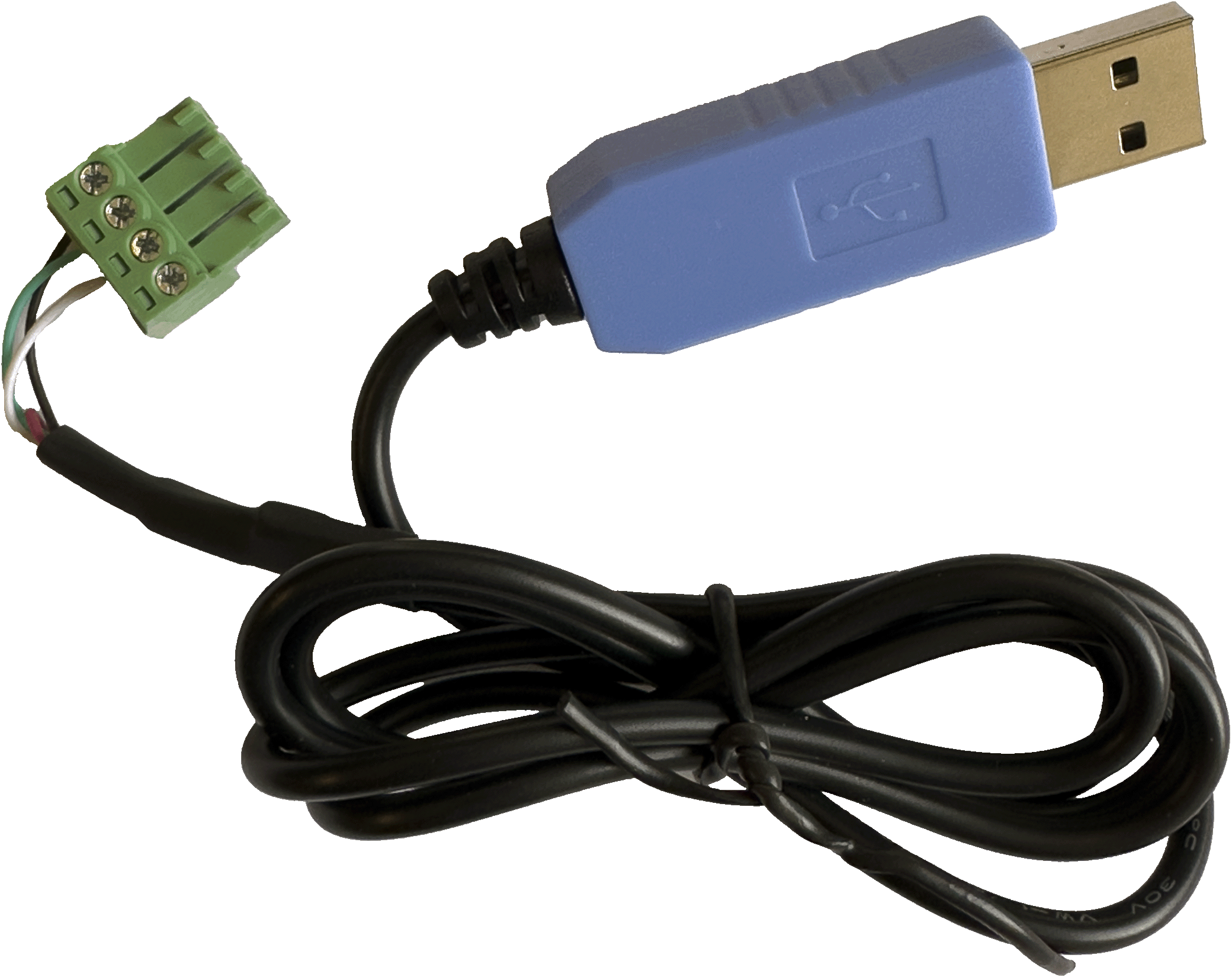
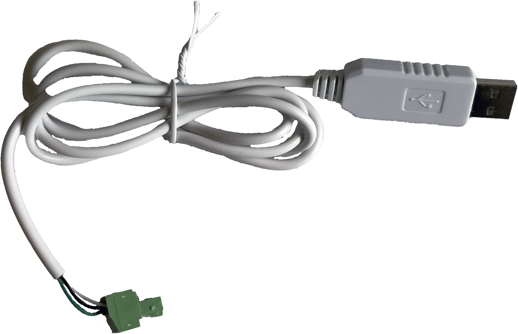
Cables for connection between battery backup and computer (USB-A).
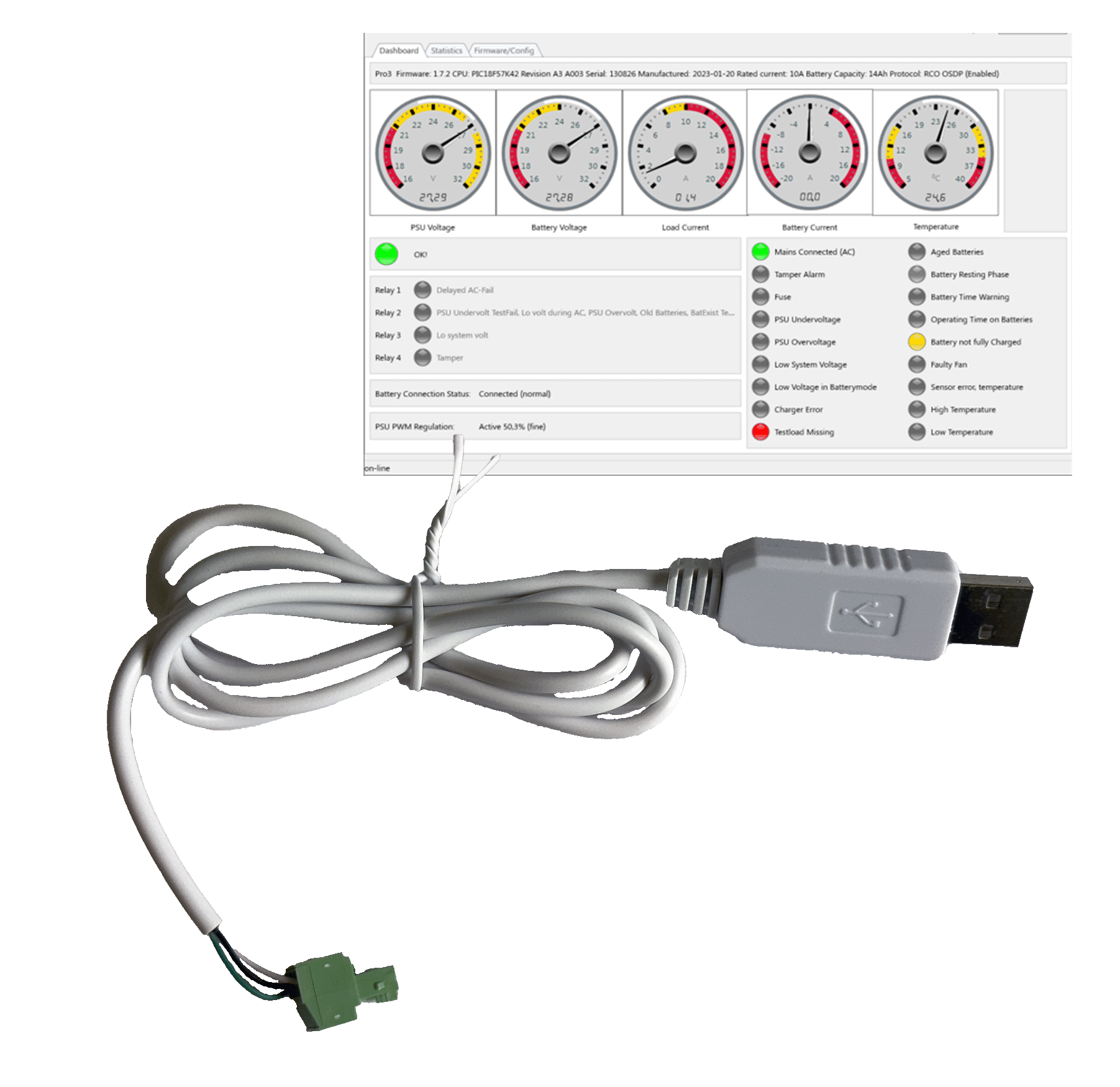
PowerWatch is available in two variants: PowerWatch (blue USB) and PowerWatch RACK (white USB).
Important
System requirements for software are: Windows 7 or later. Internet connection is needed to activate the software.
Download software and drivers
Software and drivers can be downloaded from: https://www.milleteknik.se/powerwatch/.

Installation requirements, software
The software may require the installation of drivers, see Install drivers.
Internet connection is required to activate the software.
After the software is activated against the license server, it is possible to use the software without an internet connection for 30 days.
The software downloads the correct configuration files on the server.
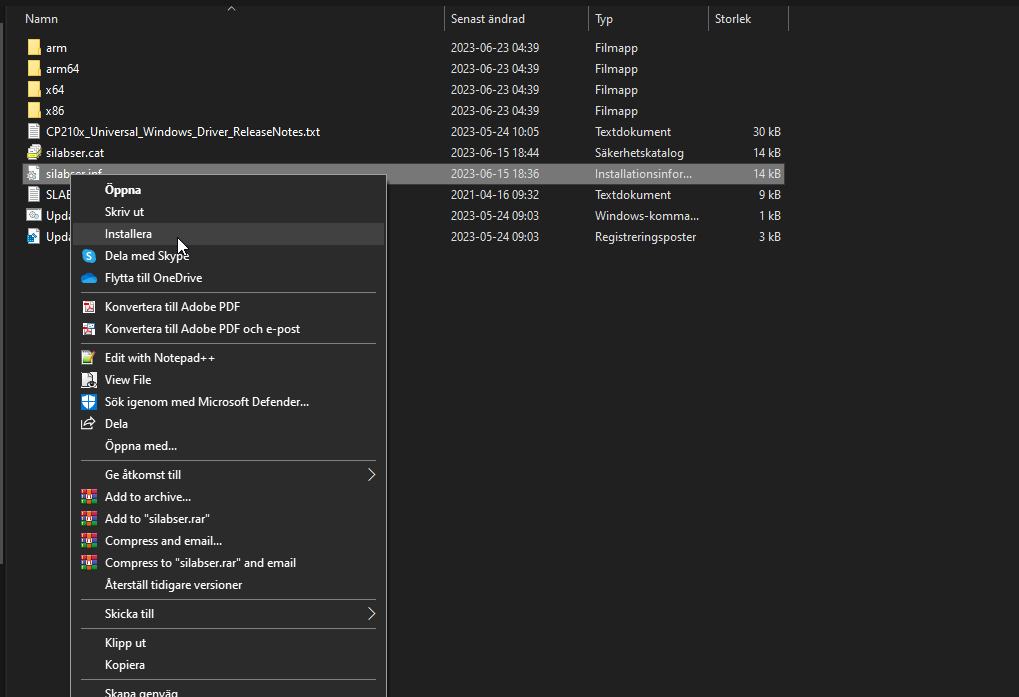
Install drivers
Download the driver from the download page.
Extract or unzip the file to a suitable folder on your computer.
Right click on syllabus.inf and select install.
Connect to PRO1 board
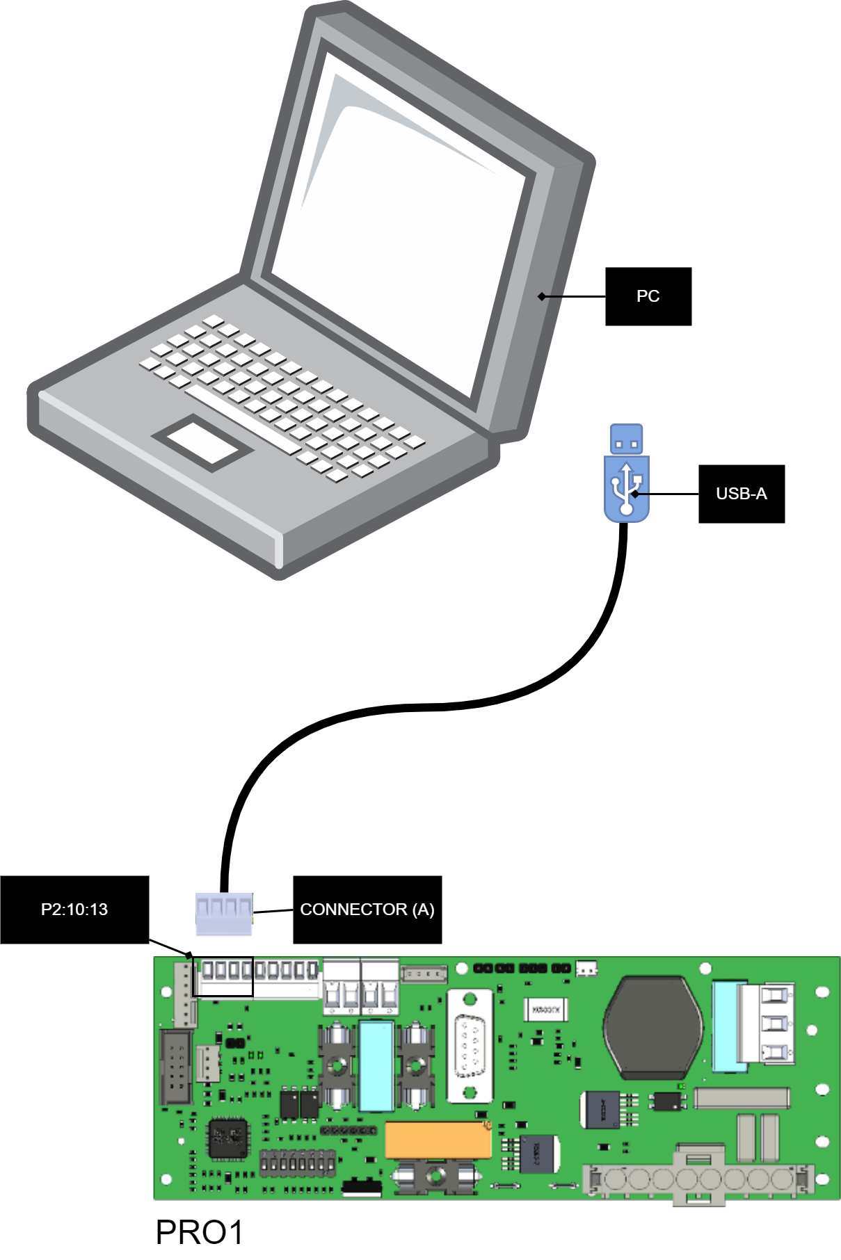
Text | Explanation |
|---|---|
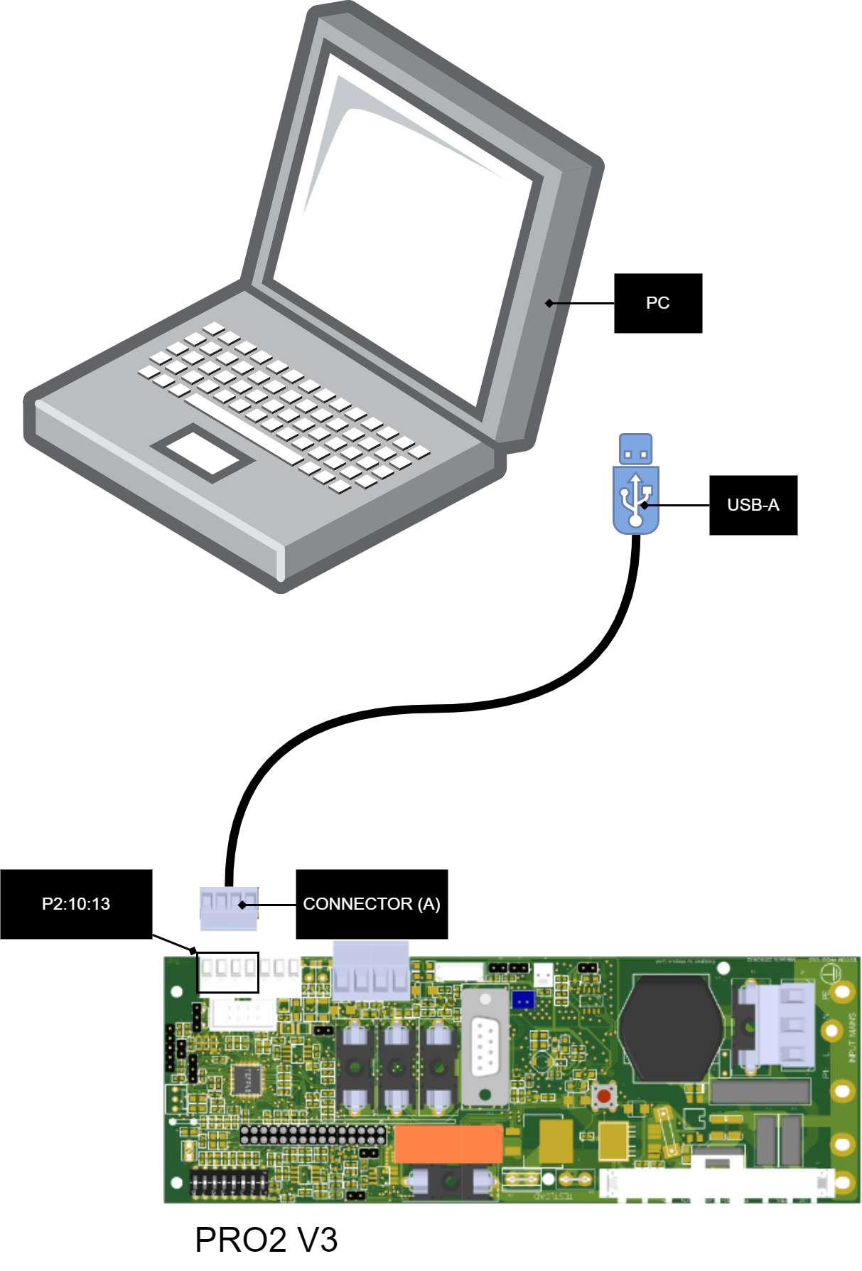
PC | PC for connecting PowerWatch. Download software and start the software before connecting to battery backup. Internet connection is required to activate the software. |
USB-A | USB connection, must be connected to PC. |
Connector (A) | Connection cable, four-pin connector must be plugged into battery backup. |
P2:10-13 | Connection to battery backup |
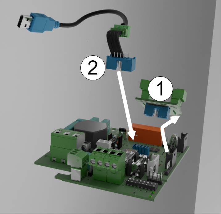
Connect to PRO2v3 board
Text | Explanation |
|---|---|
PC | PC for connecting PowerWatch. Download software and start the software before connecting to battery backup. Internet connection is required to activate the software. |
USB-A | USB connection, must be connected to PC. |
Connector (A) | Connection cable, four-pin connector must be plugged into battery backup. |
P2:10-13 | Connection to battery backup |
Important
If you have an alarm card in your unit, you can not use PowerWatch before removing this. This is because the alarm card uses the same communication bus on the processor.
Pro2 v3 with alarm card
If the Pro2 board has an alarm card installed, the alarm card must be removed when updating with PowerWatch. This is because the communication otherwise only reaches the alarm card and not ports P2:10-13 on the Pro2 card.
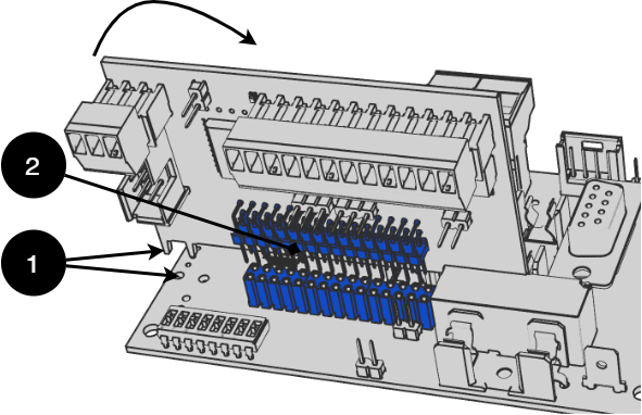
Lift the card to remove it and reseat it after the device is updated with PowerWatch.
No | Explanation |
|---|---|
1 | Insert the tags into the holes first. Then fold the card down towards the stiffener. |
2 | Pin and pin strip for connection. |
Connect to PRO3 board
Text | Explanation |
|---|---|
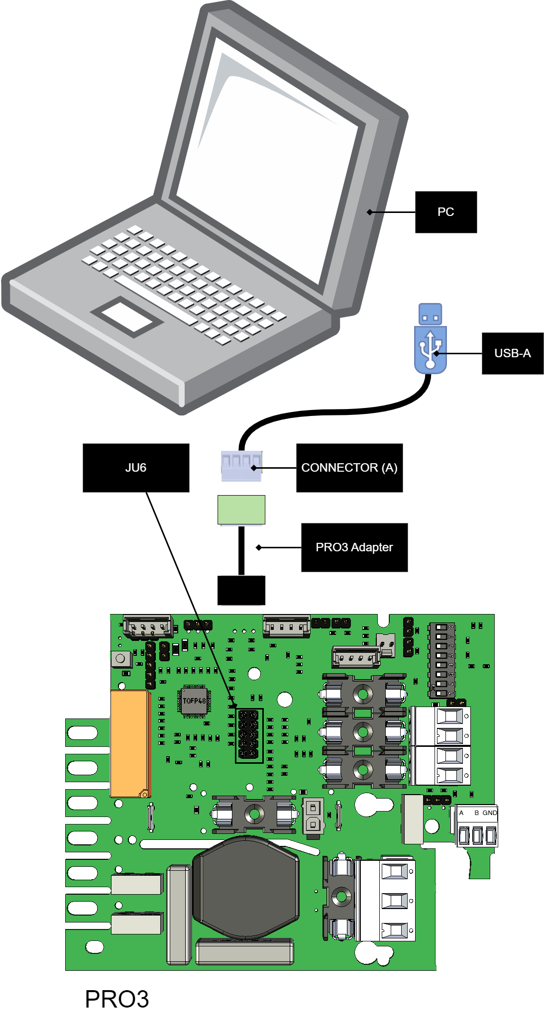
PC | PC for connecting PowerWatch. Download software and start the software before connecting to battery backup. Internet connection is required to activate the software. |
USB-A | USB connection, must be connected to PC. |
Connector (A) | Connection cable, four-pin connector must be plugged into battery backup. |
PRO3 Adapter | Adapter cable for connection to JU6. Green cable should be downwards in the picture, towards the fuse, F4. |
JU6 | Connection to battery backup |
Remove option board to connect
If there is a card on the connector where the PowerWatch is to be plugged in, then the card must be removed in order to connect the PowerWatch.
If when the card is removed an alarm can be given, then the connection to the power supply has been broken. Cards on the connector may vary.
Number | Explanation |
|---|---|
1 | Remove the card that sits on connector (JU6). |
2 | plug in the PowerWatch. |
Put the card back after the device is updated.
Connect to EN54 1U/2U
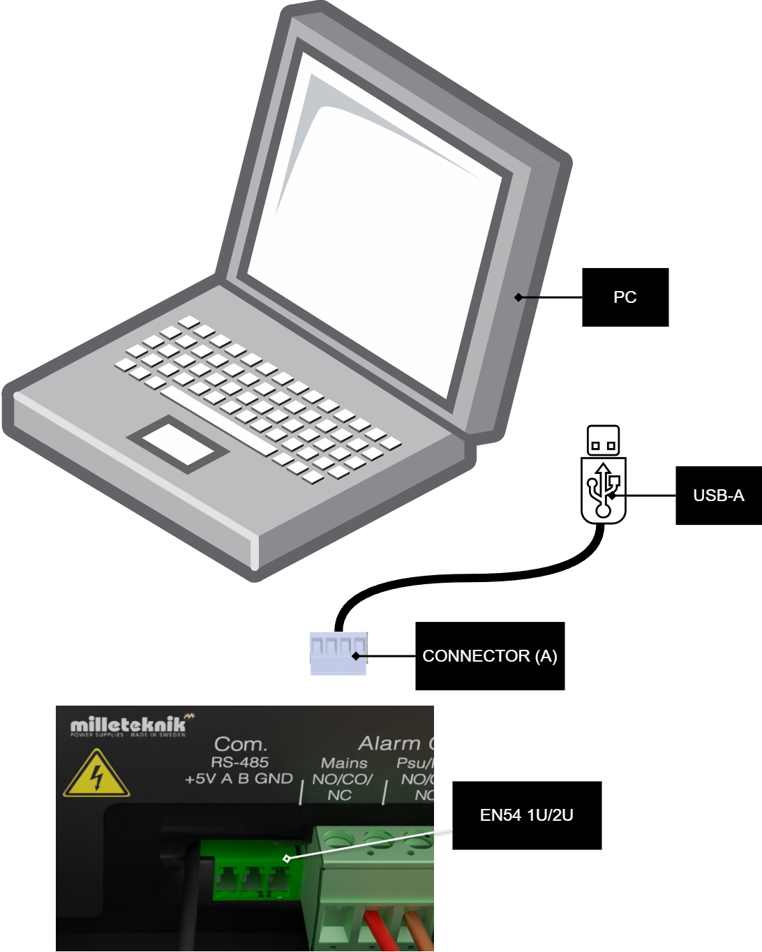
Important
For EN54 1U/2U, the PowerWatch RACK must be used.
Text | Explanation |
|---|---|
PC | PC for connecting PowerWatch. Download software and start the software before connecting to battery backup. Internet connection is required to activate the software. |
USB-A | USB connection, must be connected to PC. |
Connector (A) | Connection cable, four-pin connector must be plugged into battery backup. |
EN54 1U/2U | Connection to Battery backup |
Note on certification and update of EN54 1U/2U
In order for the certificate to be maintained after an update, a new panel/label must be placed on the device. In order to update the device, the old panel/label needs to be removed and replaced. This only applies to units delivered after 2023-07-01. Devices manufactured before this date cannot use PowerWatch.
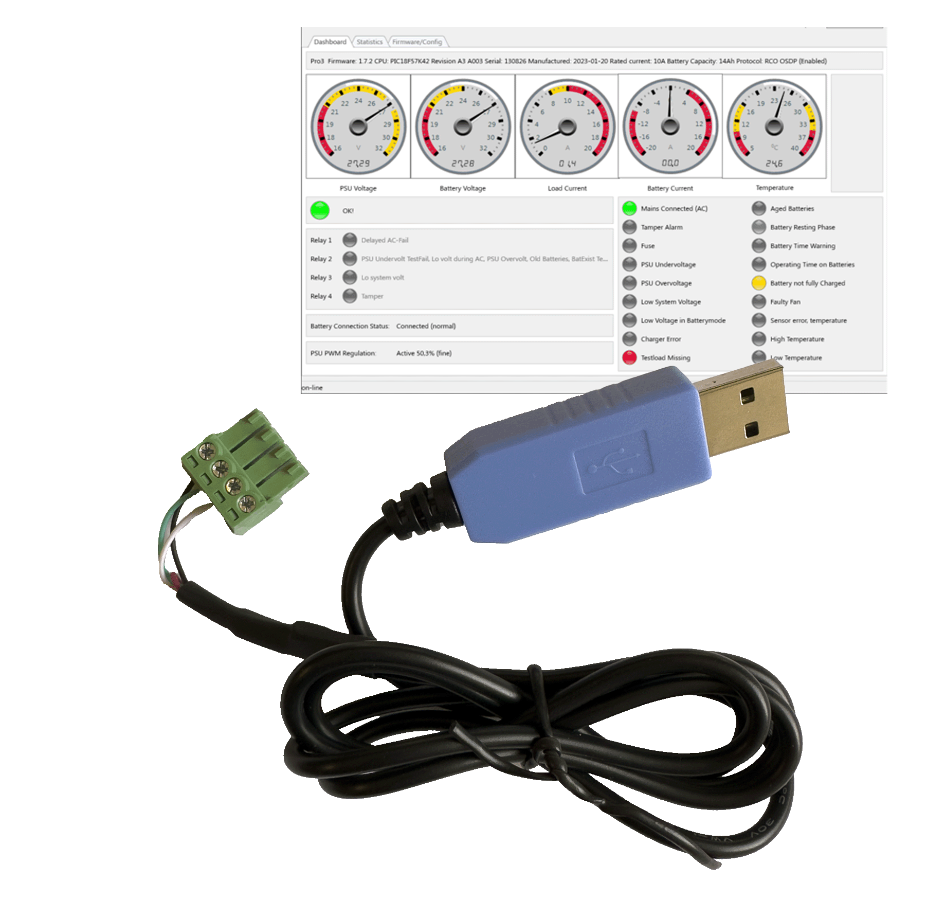
The tabs in the program
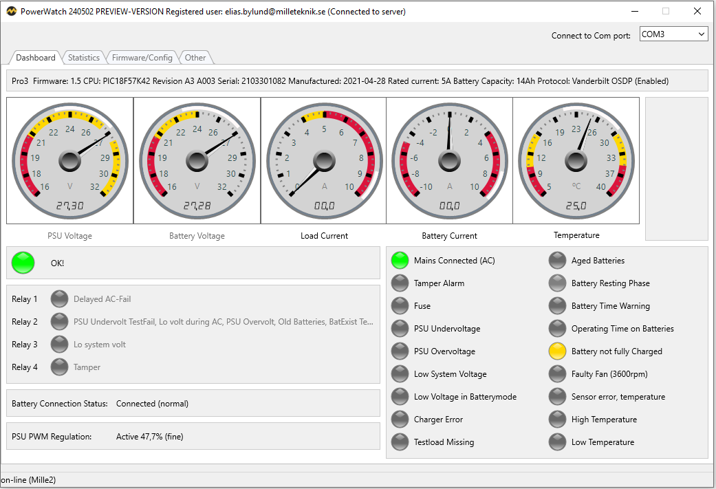
Dashboard - Overview
The Dasboard tab shows an overview showing the connected power supply status.
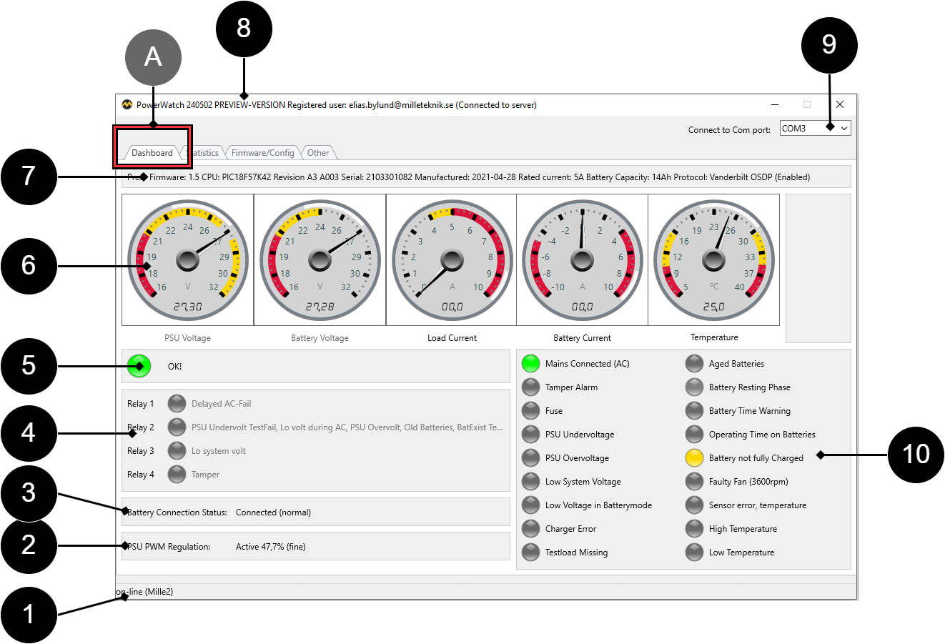
Letter/NO | Explanation |
|---|---|
A | Tab name |
1 | Connection status. |
2 | PSU PWM Regulation = power supply control. |
3 | Battery connection status. |
4 | Status of alarm relay. |
5 | Power supply status, shows the same as the LED on the device. |
6 | Meters showing ranges for: Power supply voltage, battery voltage, load current, battery current, system temperature. |
7 | Shows info about processor data and its configuration. |
8 | Shows name and version of PowerWatch and logged in user. |
9 | Connection port on computer to PowerWatch. |
10 | Status of alarms and warnings that the device displays. |
Status of alarms and warnings that the device displays - Text | Explanation | ||||||||||||||||||||||||||||||||||||||||||||||||
|---|---|---|---|---|---|---|---|---|---|---|---|---|---|---|---|---|---|---|---|---|---|---|---|---|---|---|---|---|---|---|---|---|---|---|---|---|---|---|---|---|---|---|---|---|---|---|---|---|---|
Mains Connected (AC) | Mains connection, status. | ||||||||||||||||||||||||||||||||||||||||||||||||
Tamper Alarm | Tamper alarm, status[a]. | ||||||||||||||||||||||||||||||||||||||||||||||||
Fuse | Fuses, status. | ||||||||||||||||||||||||||||||||||||||||||||||||
PSU Undervoltage | Undervoltage in charger, status. Also called charger error undervoltage. | ||||||||||||||||||||||||||||||||||||||||||||||||
PSU Overvoltage | Overvoltage in charger, status. Also called charger failure overvoltage. | ||||||||||||||||||||||||||||||||||||||||||||||||
Low System Voltage | Low system voltage, status. | ||||||||||||||||||||||||||||||||||||||||||||||||
Low Voltage in Battery mode | Low system voltage in battery operation, status. Also called low battery voltage. | ||||||||||||||||||||||||||||||||||||||||||||||||
Charger error | Charger error, status. | ||||||||||||||||||||||||||||||||||||||||||||||||
Testload Missing | Test load missing / not correctly connected, status. | ||||||||||||||||||||||||||||||||||||||||||||||||
Aged Batteries | Aged batteries, status. | ||||||||||||||||||||||||||||||||||||||||||||||||
Battery Resting Phase | Batteries in sleep phase, status. | ||||||||||||||||||||||||||||||||||||||||||||||||
Battery Time Warning | Warning for remaining time in battery operation, status. | ||||||||||||||||||||||||||||||||||||||||||||||||
Operating Time on Batteries | Remaining time in battery operation, status. | ||||||||||||||||||||||||||||||||||||||||||||||||
Battery not fully charged | Batteries not fully charged, status. | ||||||||||||||||||||||||||||||||||||||||||||||||
Faulty Fan (X XXX rpm) | Flaking error, status, (rpm is shown in parenthesis). | ||||||||||||||||||||||||||||||||||||||||||||||||
Sensor error, temperature | Error on temperature sensor / not correctly connected, status. | ||||||||||||||||||||||||||||||||||||||||||||||||
High Temperature | High temperature, status. | ||||||||||||||||||||||||||||||||||||||||||||||||
Low Temperature | Low temperature, status. | ||||||||||||||||||||||||||||||||||||||||||||||||
[a] It is normal for this to sound an alarm, as the unit should sound an alarm when the unit's door is open. | |||||||||||||||||||||||||||||||||||||||||||||||||
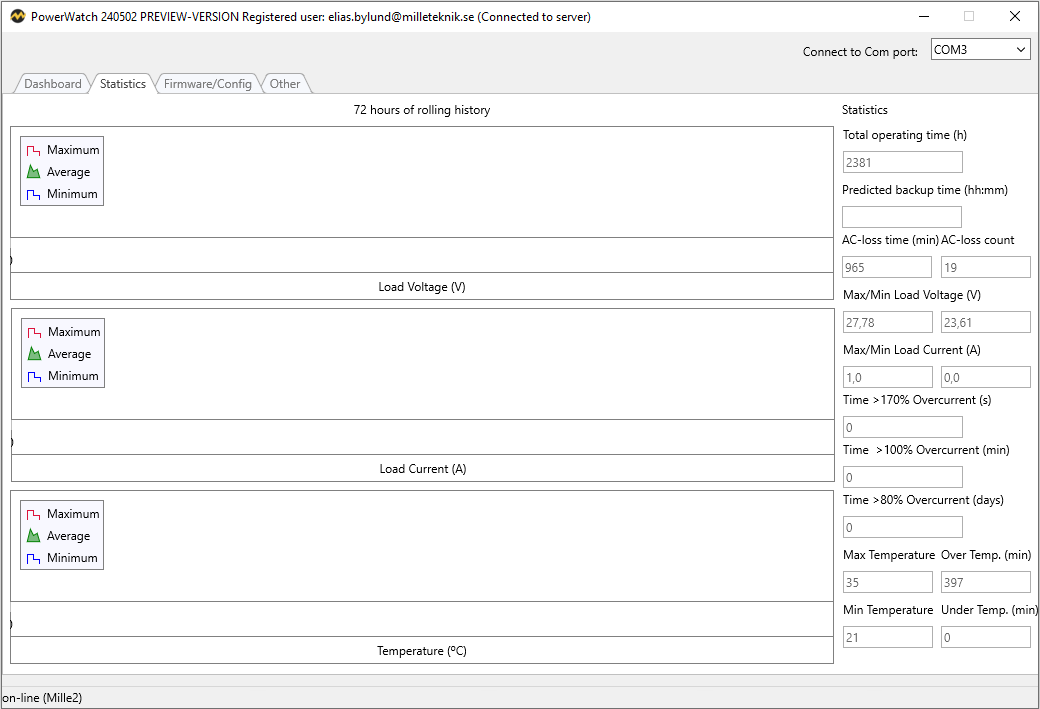
Statistics - Statistics
The Statistics tab shows an overview and statistics for the connected power supply (the last 72 h).
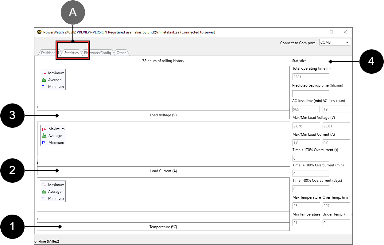
Letter/No. | Explanation |
|---|---|
A | Tab name |
1 | Statistics showing temperature, minimum, average and maximum. |
2 | Statistics showing current in Amps, minimum, average and maximum. |
3 | Statistics showing voltage in Volts, minimum, average and maximum. |
4 | Statistics on consumption. |
Statistics - text | Explanation |
|---|---|
Total operating time (h) | Operating time since the device was commissioned for the first time. |
Predicted backup time | Estimated remaining battery life. |
AC loss time (min) | Power failure, number of minutes. |
AC loss count | Grid failure, number. |
Max/Min Load Current (A) | Minimum and maximum load voltage. |
Time >170% Overcurrent (s) | Time overcurrent above 170%, in seconds. |
Time >100% Overcurrent (min) | Time overvoltage above 100%, in minutes. |
Time >80% Overcurrent (days) | Time overvoltage above 80%, in days. |
Maximum Temperature | Highest measured temperature. |
Over Temperature (min) | Number of minutes the temperature has been above max. |
My Temperature | Lowest measured temperature. |
Under Temp. (my) | Number of minutes the temperature has been below the minimum permitted temperature. |
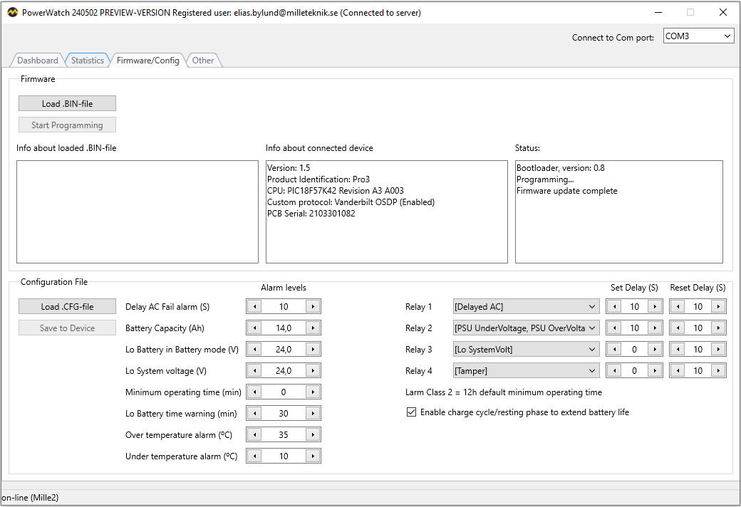
Firmware/Config - Firmware/Configuration
The Firmware/Config tab shows a shows info about connected power supply software and configuration.
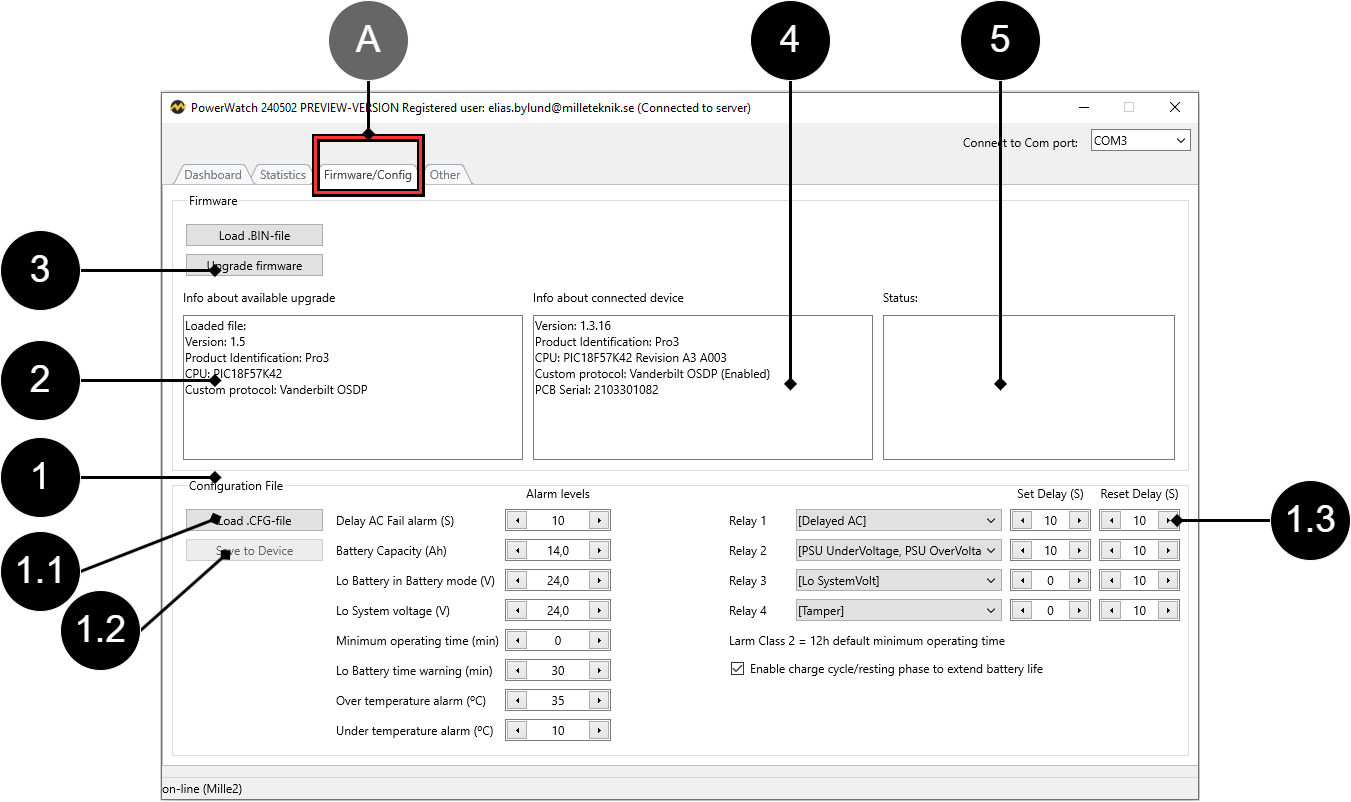
Letter/No. | Explanation | ||||||||||||||||||||||||||||||||||||||||||||||||
|---|---|---|---|---|---|---|---|---|---|---|---|---|---|---|---|---|---|---|---|---|---|---|---|---|---|---|---|---|---|---|---|---|---|---|---|---|---|---|---|---|---|---|---|---|---|---|---|---|---|
A | Tab name | ||||||||||||||||||||||||||||||||||||||||||||||||
1 | The field shows info and configurations that can be set. | ||||||||||||||||||||||||||||||||||||||||||||||||
1.1 | The button "Load .CFG file" loads new configuration file[a]. | ||||||||||||||||||||||||||||||||||||||||||||||||
1.2 | The "Save to Device" button saves the configuration file to the power supply. | ||||||||||||||||||||||||||||||||||||||||||||||||
1.3 | Relay 1-4, it is possible to change the type of alarm to be given via alternating relay. It is also possible to set the time if the alarm is to be delayed[b]. | ||||||||||||||||||||||||||||||||||||||||||||||||
2 | Info box for downloaded/loaded firmware file. | ||||||||||||||||||||||||||||||||||||||||||||||||
3 | Button to upgrade firmware. See Updating firmware in power supply. | ||||||||||||||||||||||||||||||||||||||||||||||||
4 | Device software information box. | ||||||||||||||||||||||||||||||||||||||||||||||||
5 | Status pane displays information about the device's status (if any). | ||||||||||||||||||||||||||||||||||||||||||||||||
[a] It is not possible to change custom device to other type of device. [b] Do not change these alarms if you have a certified device, as alarms must be configured as the device was delivered. | |||||||||||||||||||||||||||||||||||||||||||||||||
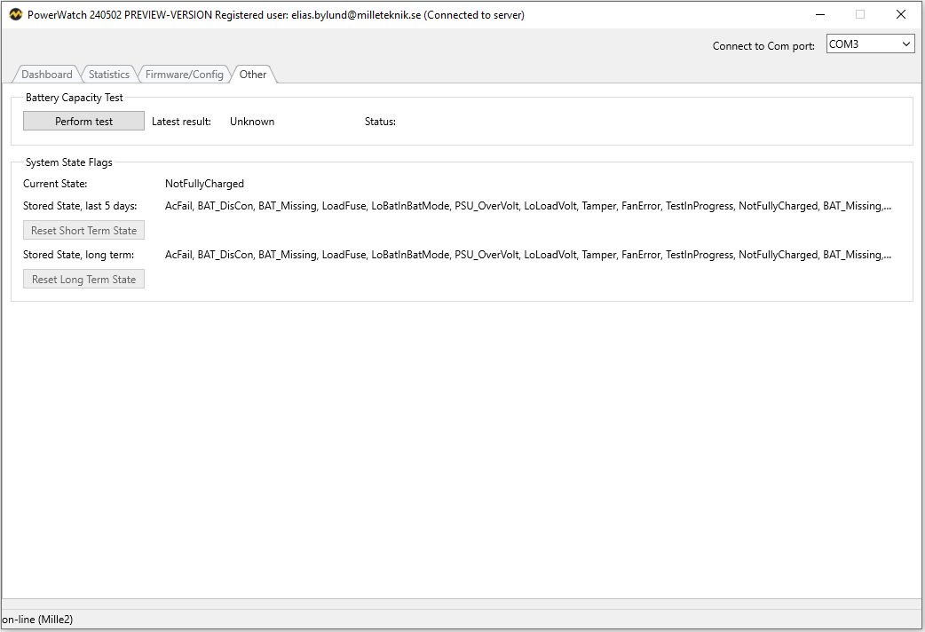
Other - Other
The Other tab shows various system settings (flags) and has the option to implement one [1]capacity test for batteries.
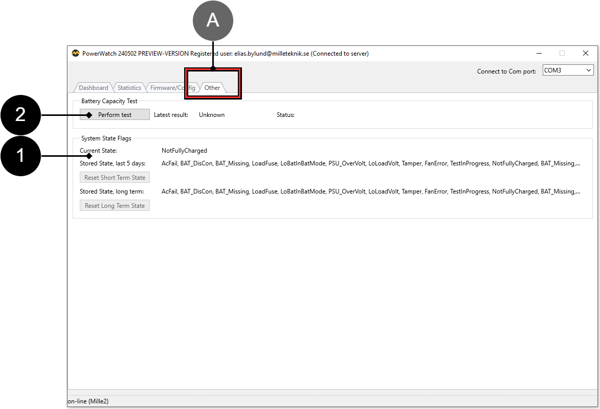
Letter/NO | Explanation |
|---|---|
A | Tab name |
1 | System State Flags: Status of the system's flags. "Stored State, last 5 days" shows the last 5 days. "Stored State, long term" shows the flags after the last 5 days. |
2 | Battery Capacity Test. Press the "Perform test" button to test the batteries' capacity. |
Help - Help
The tab shows links to help pages and manuals. Developing.
What happens after update?
After updating the software via PowerWatch, the battery backup is restarted automatically.
Firmware and configuration files - what's the difference?
Firmware is the software that controls the device's basic functions, this may need to be updated with bug fixes to ensure operation and function.
Examples of basic functions that the firmware controls are power distribution and control signals from power supplies.
The configuration file controls how the software can be used. Different cards have different possibilities to use functions through software and the configuration file gives instructions to the firmware so that the correct functions are used.
Examples of features that the configuration file controls are communication protocols and internal current limit ranges.
For the device to work, both files are needed. A tag in an access system needs to have both a tag (firmware) and a code (configuration file) to work.
Tip
Firmware can be used for all devices in the product series.
Configuration file can only be used for products with the same voltage and current configuration.
Updating firmware in power supply
If there is a new firmware update for the power supply, a message window will appear automatically when the software is started and connected to the power supply.
If you click Yes, new firmware will be downloaded and installed.
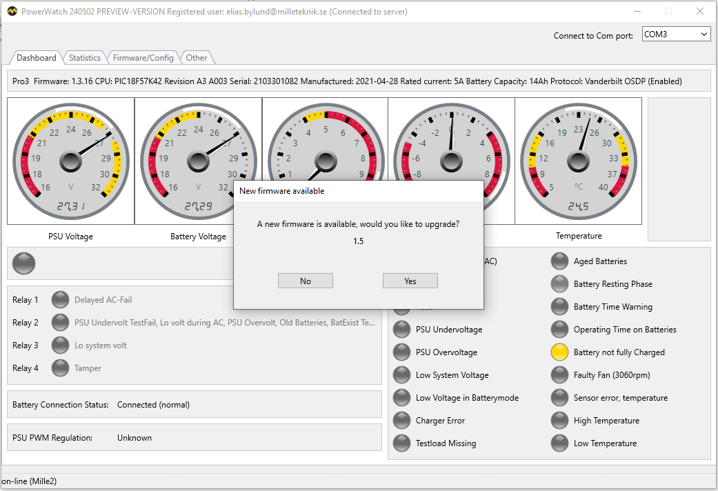
1. The program has found a new firmware update.
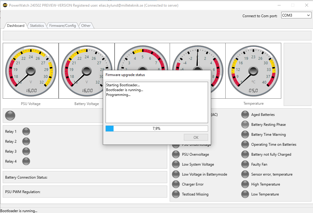
Firmware is being downloaded.
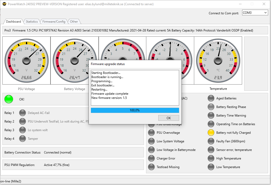
Firmware has been installed successfully.
Status displayed after firmware is installed.
Statistics for the last 72 hours are cleared when updating the firmware. Statistics related to the device since its launch are not cleared during the update.
Info about Firmware confirms update.
Info about battery tests and system flags (alarm settings) are displayed.
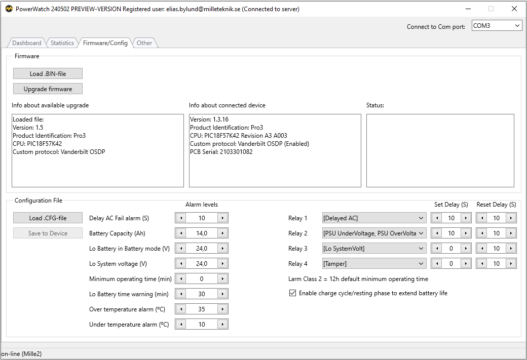
If No is pressed instead of updating the firmware, information about the update will be displayed (box on the left). Tap "Upgrade Firmware" to update the device.
Restrictions
Firmware: Update can only be done to the same communication protocol. It is therefore not possible to update to another communication protocol.
Configuration: It is only possible to update to the same device type, current, voltage. It is possible to set the battery capacity, but it is not possible not to change the type of product, but the product is what the nameplate indicates. Example: if you change batteries from 14 Ah batteries to 20 Ah batteries in a NOVA 24V 15A FLX M, you set a new battery capacity. It is never possible to change the voltage, load amperage or communication protocol.
Technical specifications
Info | Comment | ||||||||||||||||||||||||||||||||||||||||||||||||
|---|---|---|---|---|---|---|---|---|---|---|---|---|---|---|---|---|---|---|---|---|---|---|---|---|---|---|---|---|---|---|---|---|---|---|---|---|---|---|---|---|---|---|---|---|---|---|---|---|---|
PowerWatch | Software[a], requires PC and Windows 7 or later and internet connection (for activation). | ||||||||||||||||||||||||||||||||||||||||||||||||
USB - battery backup | Cable for connection to Battery backup and computer. USB-A. | ||||||||||||||||||||||||||||||||||||||||||||||||
[a] Milleteknik cannot provide support for problems that may arise in the computer if PowerWatch does not work. The software is used at your own risk and is not covered by warranty. Milleteknik does not guarantee that the software will function as intended. Milleteknik does not reimburse any costs that may arise in connection with the use of the software. | |||||||||||||||||||||||||||||||||||||||||||||||||
About translation of this document
User manual and other documents are in the original language in Swedish. Other languages may be machine translated and/or not reviewed, errors may occur.
Address and contact details
Milleteknik AB |
Ögärdesvägen 8 B |
S-433 30 Partille |
Sweden |
+46 31 340 02 30 |
info@milleteknik.se |
www.milleteknik.com |
[1] For compatible power supplies.