How the software is accessed in the PoE Switch
This section shows how to log in to the switch's configuration web page.
To configure the software in the switch, the correct IP address needs to be set on the computer.
Access to the switch's software is through a browser, (such as: Chrome, Edge, Firefox, etc.).
Follow the steps to access the switch's settings.
Note
The settings shown are settings for PC, (Windows 7 - Windows 11). Windows and names may vary between different versions of Windows. Unfortunately, we cannot provide support for settings of your computer.
Note
IP address of the switch (factory setting): 192.168.2.1
Password (factory setting): admin
Notice
The address of the PoE switch is: 192.168.2.1 and username and password are: admin/admin The IP address in the switch is static (fixed) and therefore the computer's IP address and subnet mask must be static.
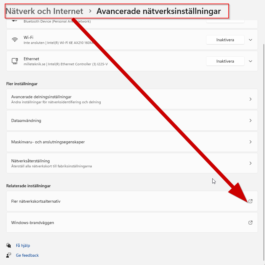
Open settings and go to Network and Internet -> Advanced network settings. Open more network card options.
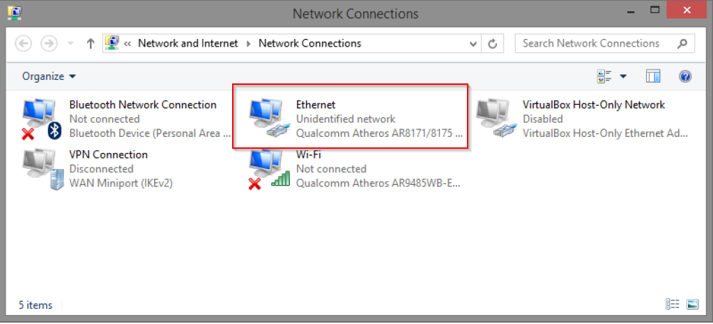
A Network Connections window will appear showing all available network connections on the computer. Double-click the network connection you use to connect to the switch.
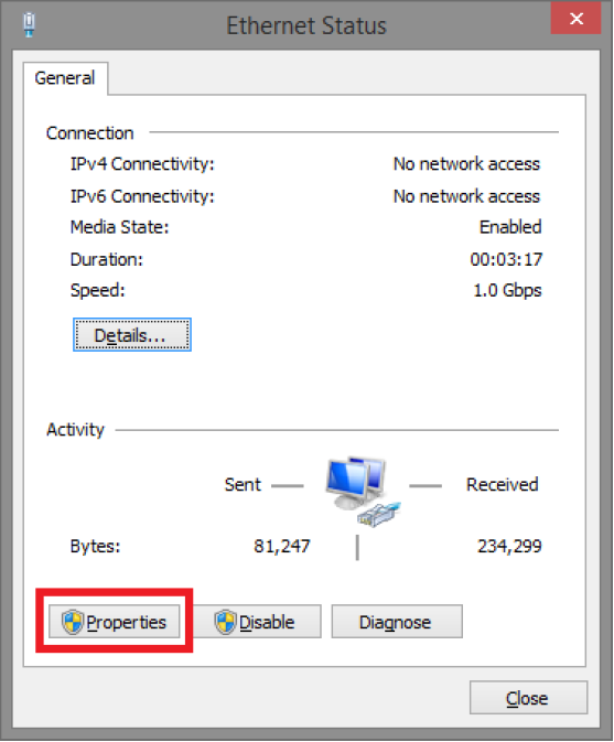
Ethernet status window appears. Click the button Characteristics as shown in the figure below.
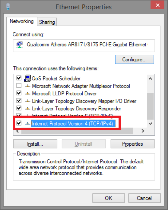
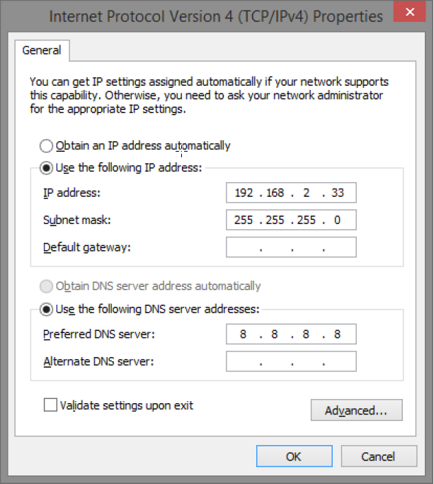
Double-click: Internet Protocol Version 4 (TCP / IPv4).
Set the computer's IP address and subnet mask as shown in the figure below. By default, the product's IP address be 192.168.2.1. You can set any IP address as long as it is not the same as your switch's IP address and is in the same network segment as your switch's IP address. Press on OK to apply the TCP/IPv4 settings you just made. Now you can connect to your switch using a web browser (Chrome, Edge or Firefox).
Connect an RJ-45 cable and connect to the PoE switch.
Log in to the PoE switch
Note
IP address of the switch (factory setting): 192.168.2.1
Password (factory setting): admin
Note
If you get a warning that the page is not secure/the connection is not private, click "advanced" and then "continue".
Start the browser on your computer.
Login to PoE switch.
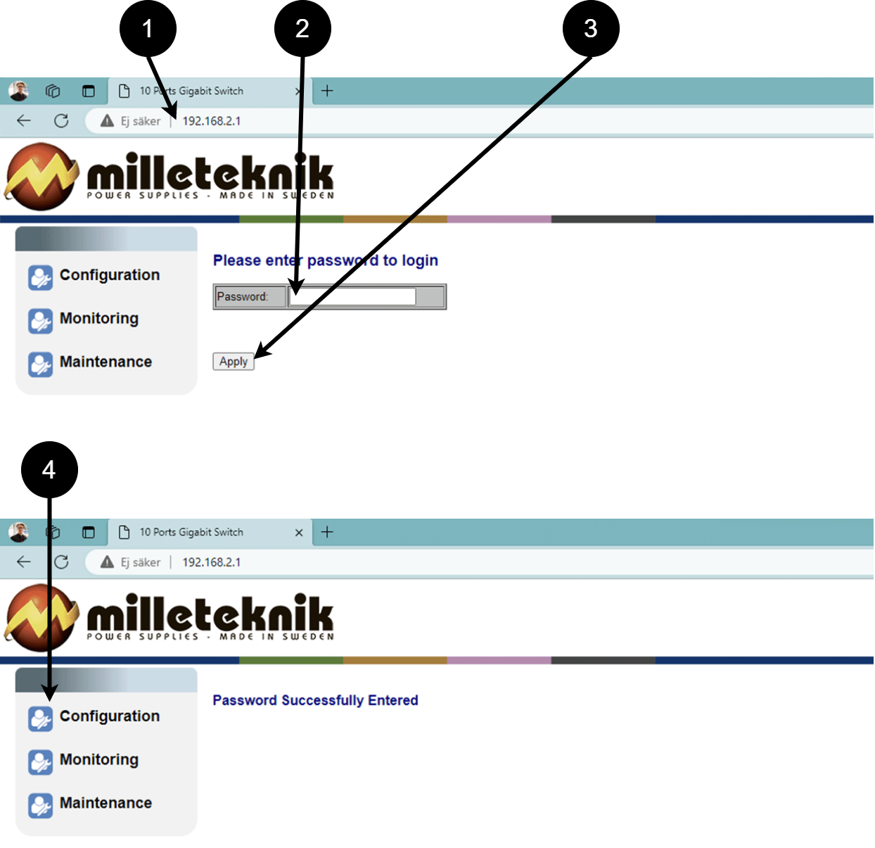 Table 1. Log in to the switch.
Number
Explanation
1
IP address of the PoE switch: 192.168.2.1
2
Password: admin
3
Apply = Ok
4
Menu in the PoE switch
Configuration
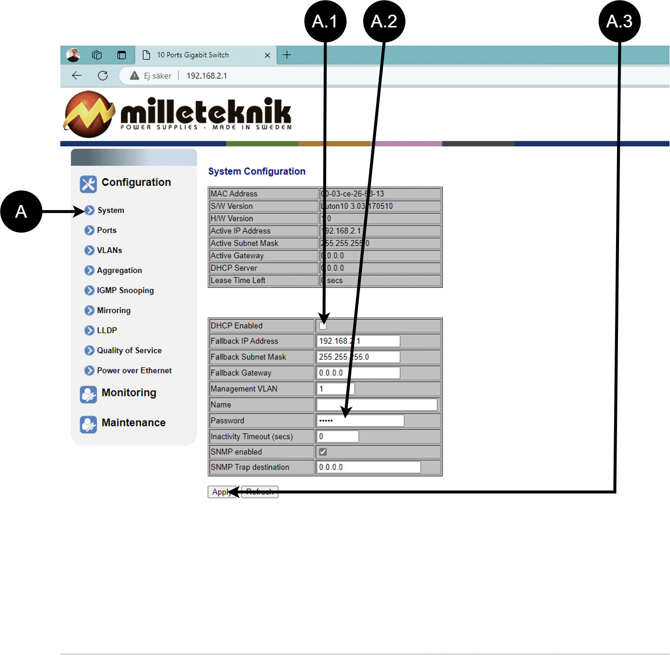
System, configuration
Letter, number | Explanation |
|---|---|
A | PoE switch system configuration page |
A.1 | Tick here if you are going to use DHCP, see warning below. |
A.2 | Changes the factory default password, (admin). |
A.3 | If you have made any changes, you need to click "Apply" to save the changes. |
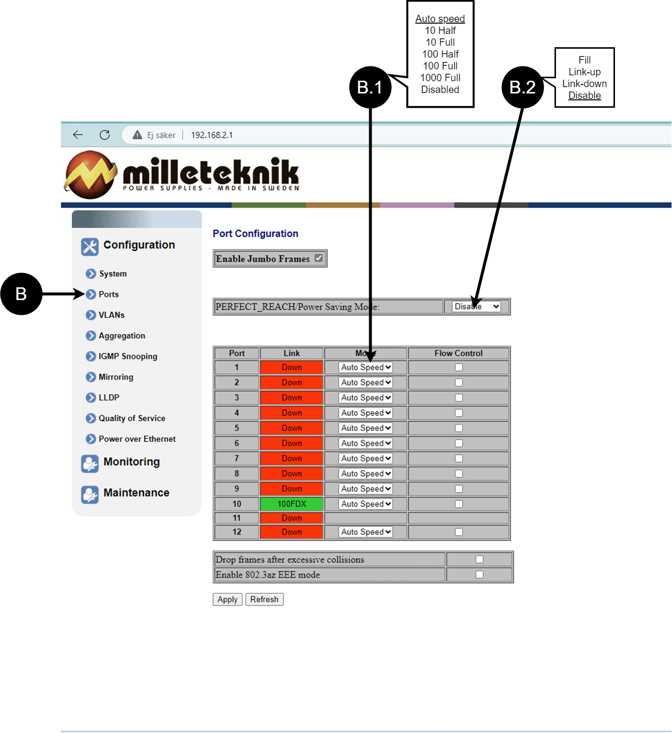
Ports, configuration
Letter, number | Explanation |
|---|---|
B | Gates |
B.1 | This setting normally does not need to be changed. Select the speed of the PoE switch's ports. |
B.2 | This setting normally does not need to be changed. |
VLAN configuration
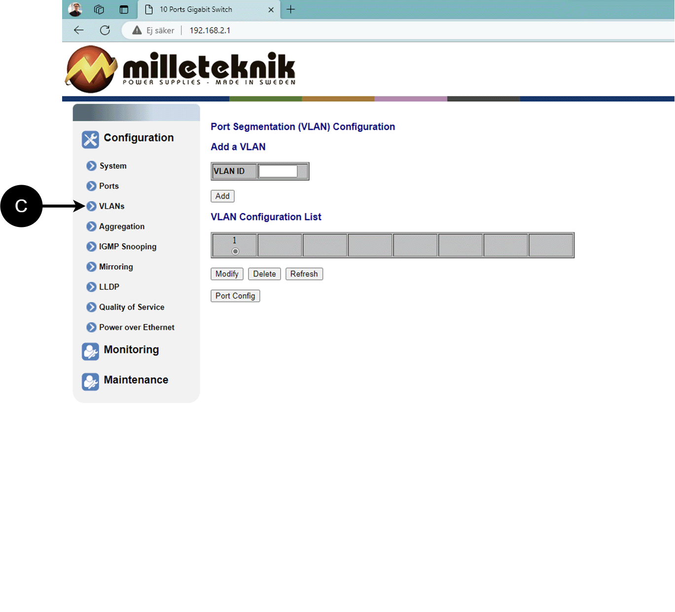
C: Configuration of Virtual LAN.
Aggregation, configuration
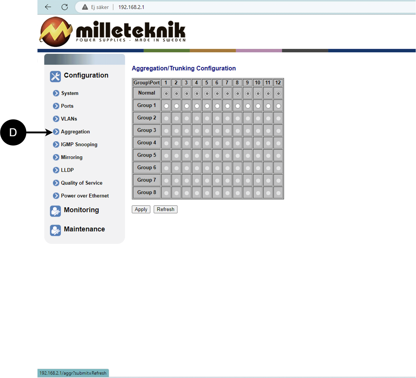
D: Load balancing between the ports.
IGMP Snooping, configuration
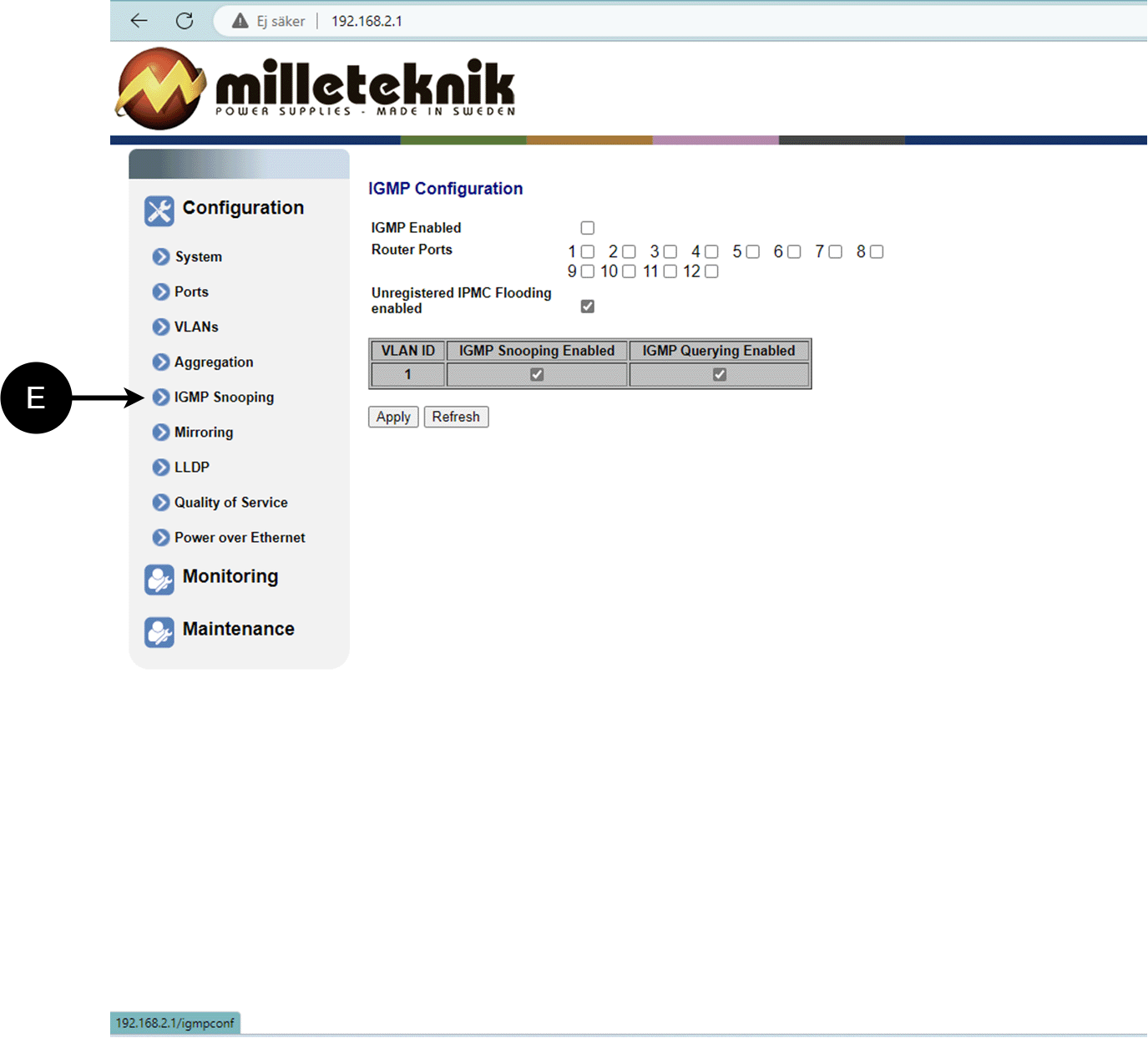
E: Switch that controls reception.
Mirroring, configuration
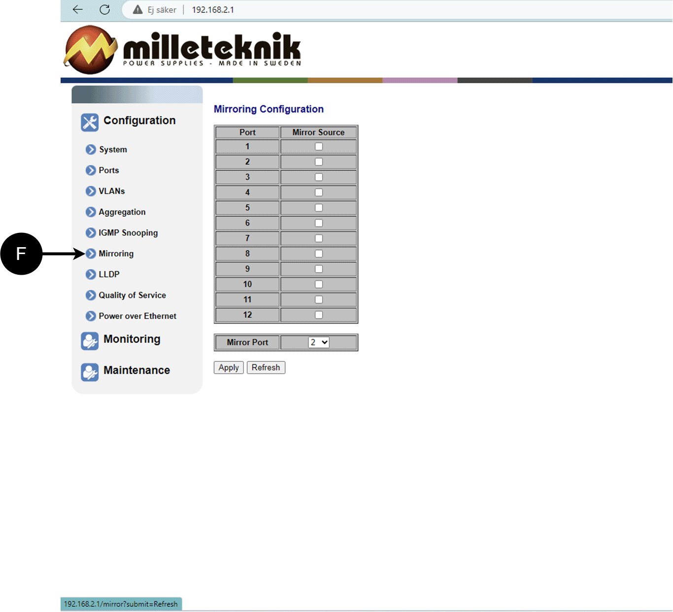
F: Mirroring of ports.
LLDP configuration
Letter, number | Explanation |
|---|---|
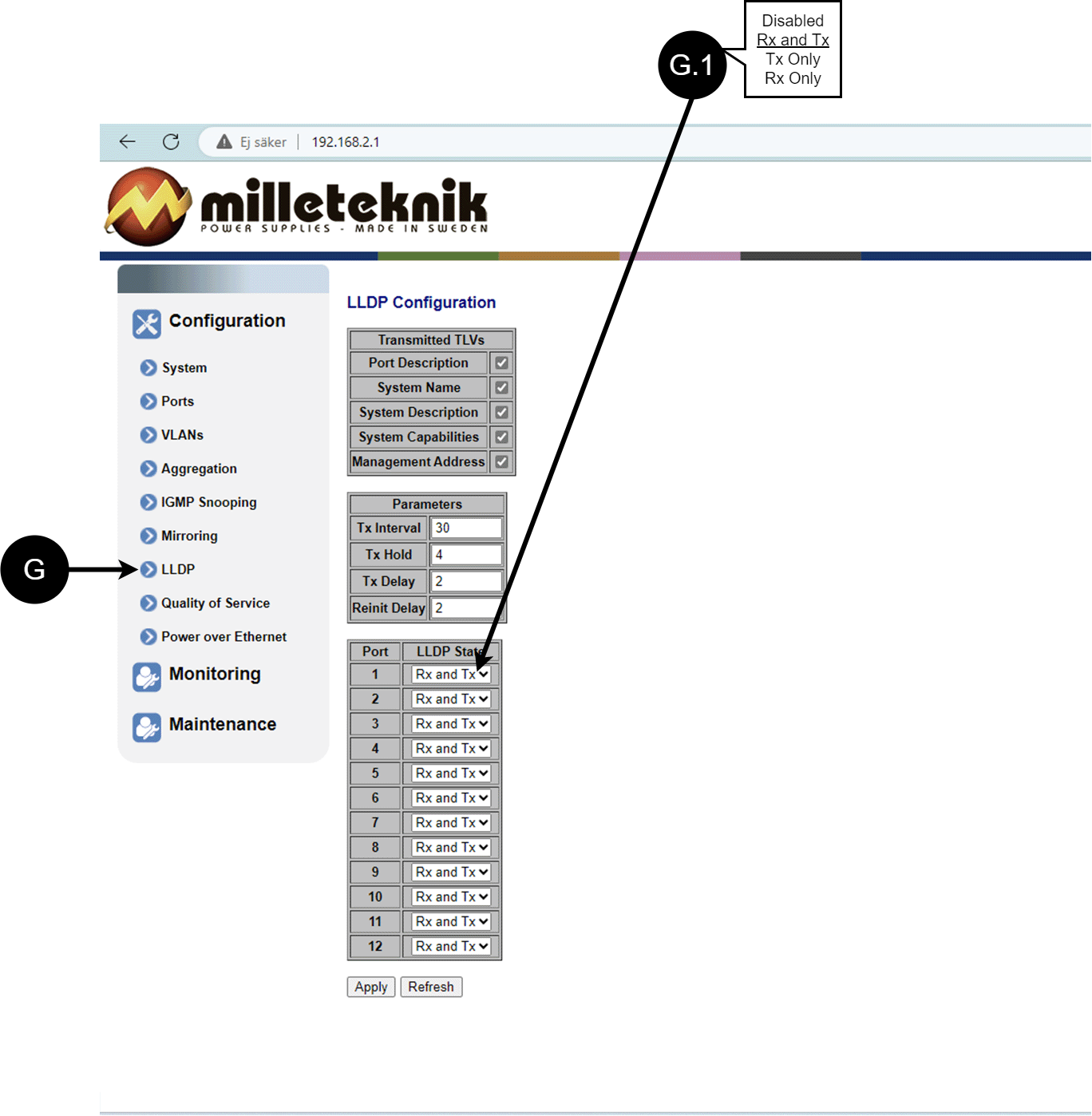
G | LLDP stands for "Link Layer Discovery Protocol", which is a network protocol standard used to discover and communicate information about network devices connected to the same Ethernet network. The protocol allows devices such as switches and routers to send and receive messages containing information about the device's identification, capabilities, and connection topology. |
G.1 | RX and TX are abbreviations used in electronics, communications, and computer networking to indicate the direction of data flow between devices. RX: The abbreviation "RX" stands for "Receive" or "Reception". It indicates that the device is receiving data or signals from another device. When a device has an RX input, it means that it is designed to receive data or information from a transmitting device. TX: The abbreviation "TX" stands for "Transmit" or "Transmission". It indicates that the device is transmitting data or signals to another device. If a device has a TX output, it means that it is designed to transmit data or information to a receiving device. These abbreviations are especially common when it comes to data communication, such as in the context of network cables where there are specific RX and TX wires that allow for two-way communication between devices. |
QoS, configuration
Letter, number | Explanation |
|---|---|
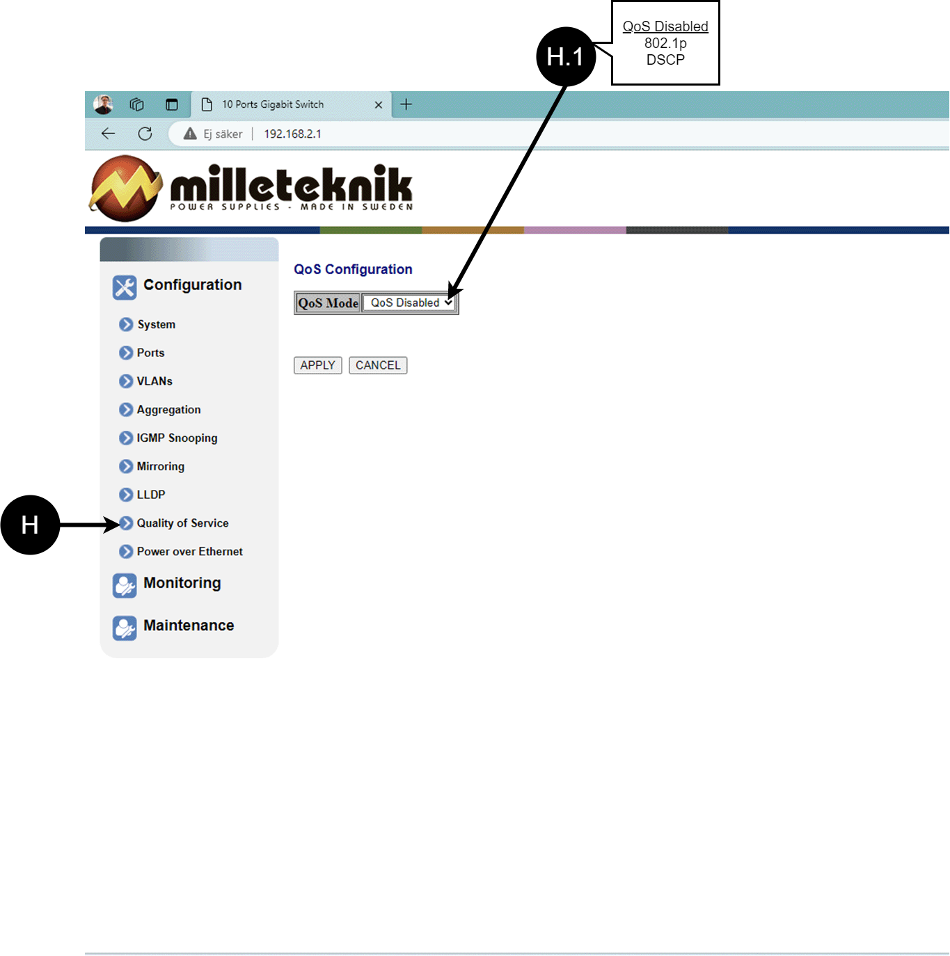
H | QoS gives different network traffic different priority, helping to ensure that important services are delivered with sufficient bandwidth and minimal delay even when the network is under load. |
H.1 | Sets whether QoS is active. |
PoE, configuration
Letter, number | Explanation |
|---|---|
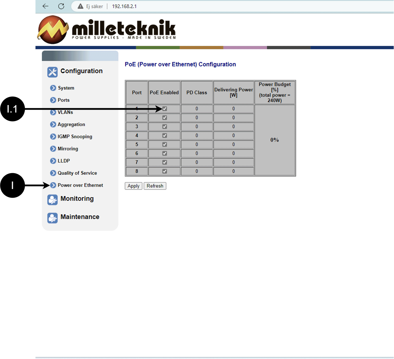
I | Power over Ethernet |
I.1 | Turns PoE function/port on or off. Remember to press "Apply" to save changes. |
Monitoring
Statistics, overview
Letter, number | Explanation |
|---|---|
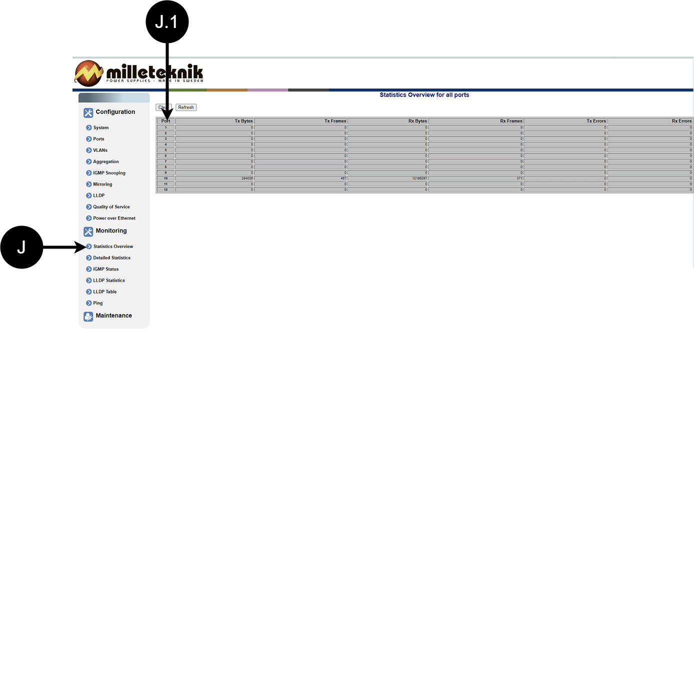
J | Statistics, overview |
J.1 | Traffic per port. |
Statistics, detailed
Letter, number | Explanation |
|---|---|
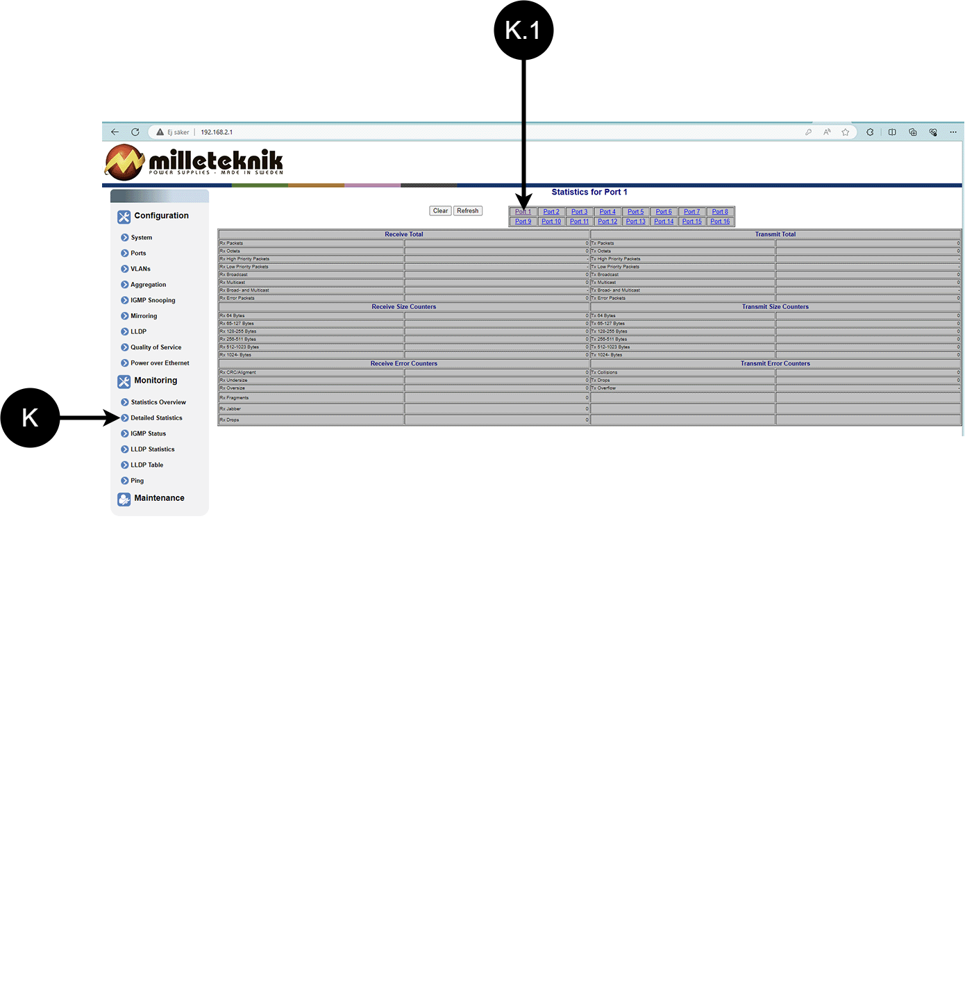
K | Detailed statistics |
K.1 | Select the port for which you want statistics. |
IGMP status
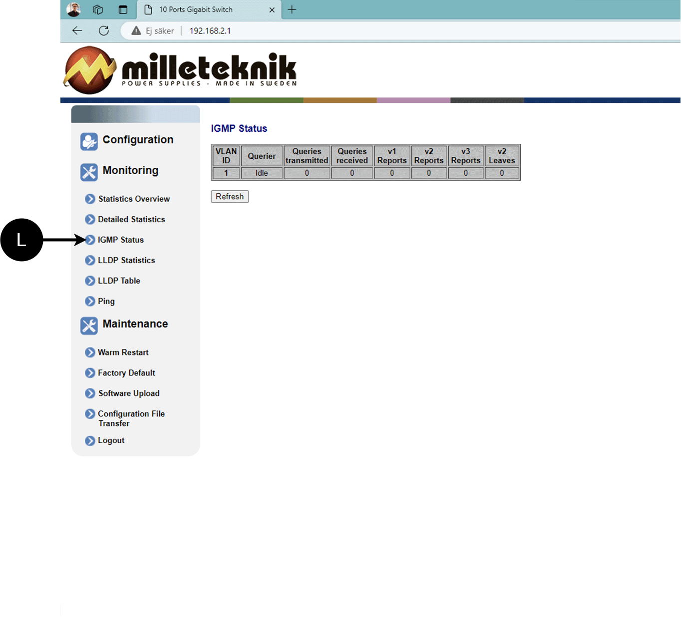
L: Status of IGMP
LLDP statistics
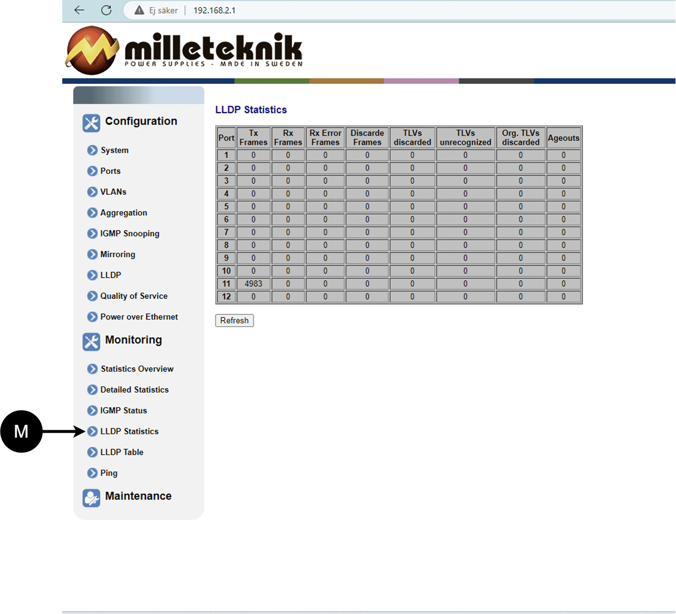
M: LLDP statistics
LLDP table
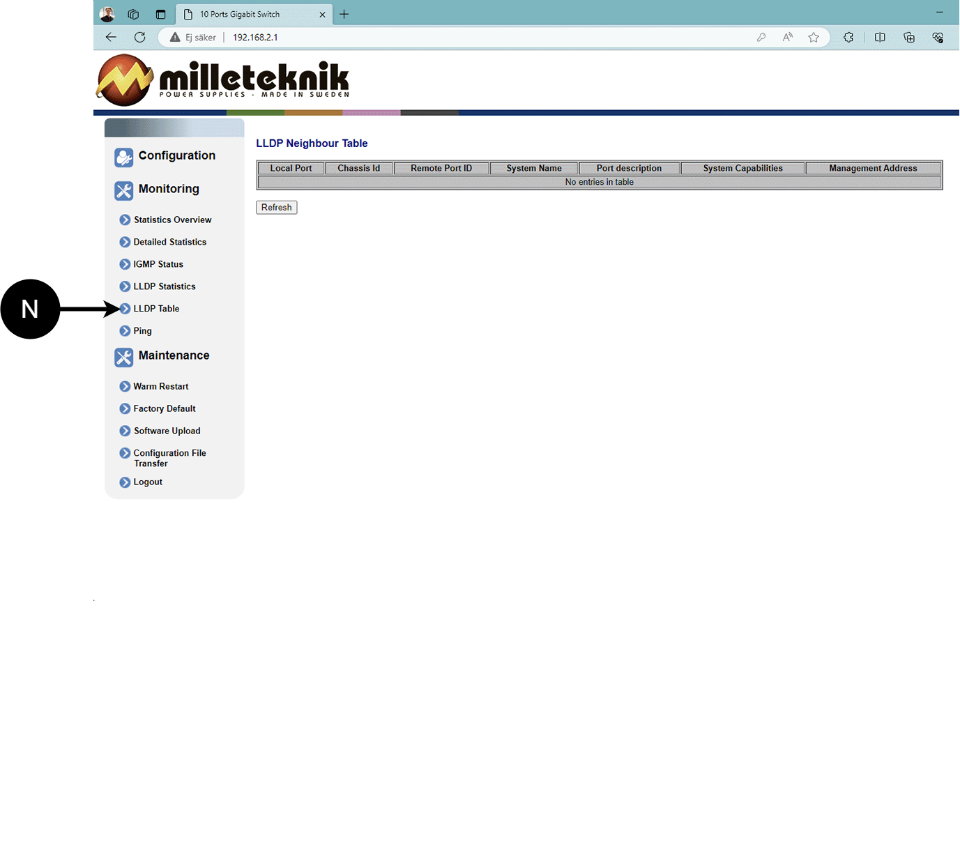
N: LLDP overview.
Ping
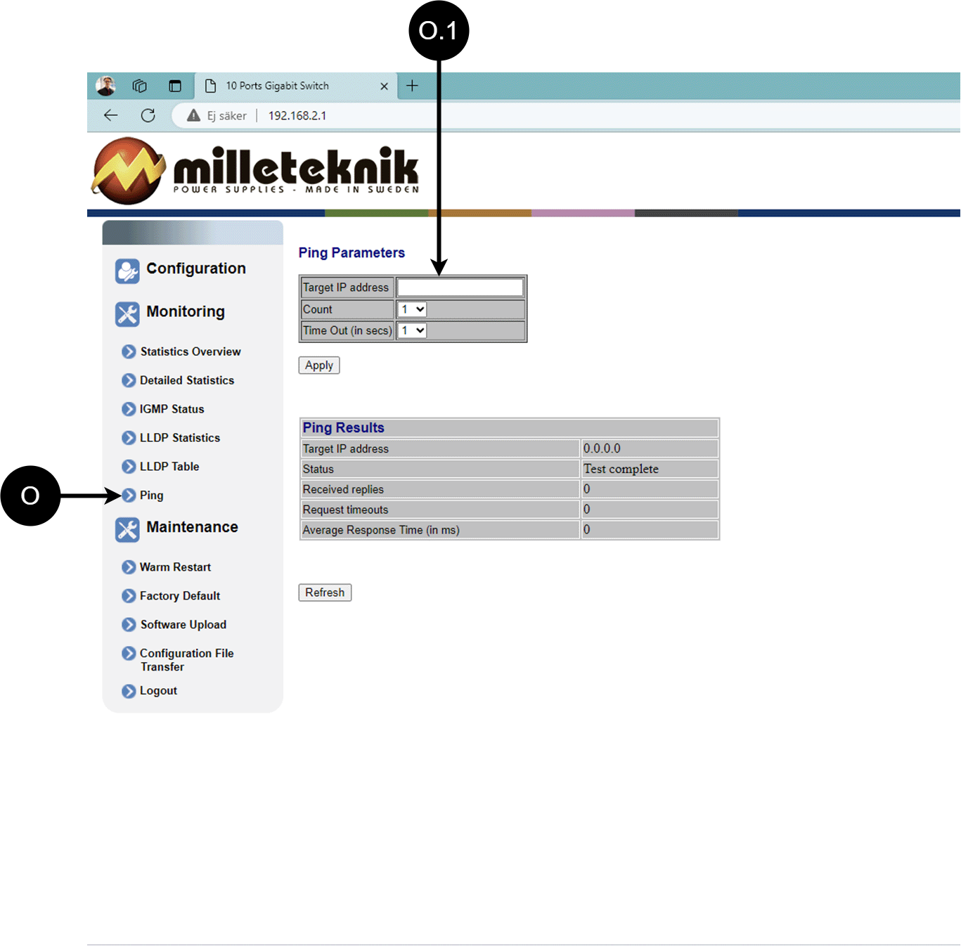
Letter, number | Explanation |
|---|---|
O | Ping |
[sv] O.1 | Input address to test the connection and response time. |
Maintenance
Reboot
Warning
Restart is done by PoE switch, battery backup is not restarted. Upon reboot, connected devices will lose connection. Alarm can be set to battery backup, but it disappears when the PoE switch is back on.
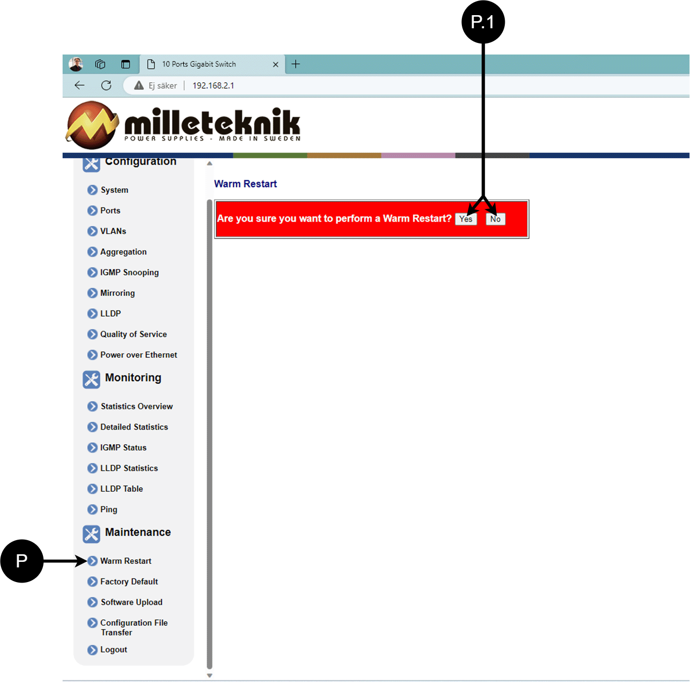
Letter, number | Explanation |
|---|---|
P | Rebooting the PoE switch. |
P.1 | Select "Yes" to reboot the switch. |
Factory reset
Warning
Factory reset is done by PoE switch. Battery backup is not restored. On reset, connected devices will lose connection. Alarm can be set to battery backup, but it disappears when the PoE switch is back on.
Important
During a factory reset, all settings, including IP settings, are lost. Save configuration before factory reset. See Upload new software

Letter, number | Explanation |
|---|---|
Q | Factory reset the PoE switch. |
Q.1 | Select "Yes" to factory reset the PoE switch. |
Upload new software
Warning
Only use software you received from Milleteknik's support. Milleteknik assumes no responsibility for software or consequences such as damage to the device or peripheral equipment or other damage that may arise from uploading unapproved software.
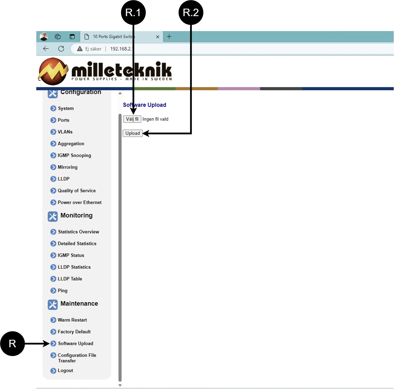
Letter, number | Explanation |
|---|---|
R | Upload new software to the Switch. |
R.1 | Navigate to the location on your computer where you saved the file. |
R.2 | Click "Upload" to upload the software. |
Load and save configuration file
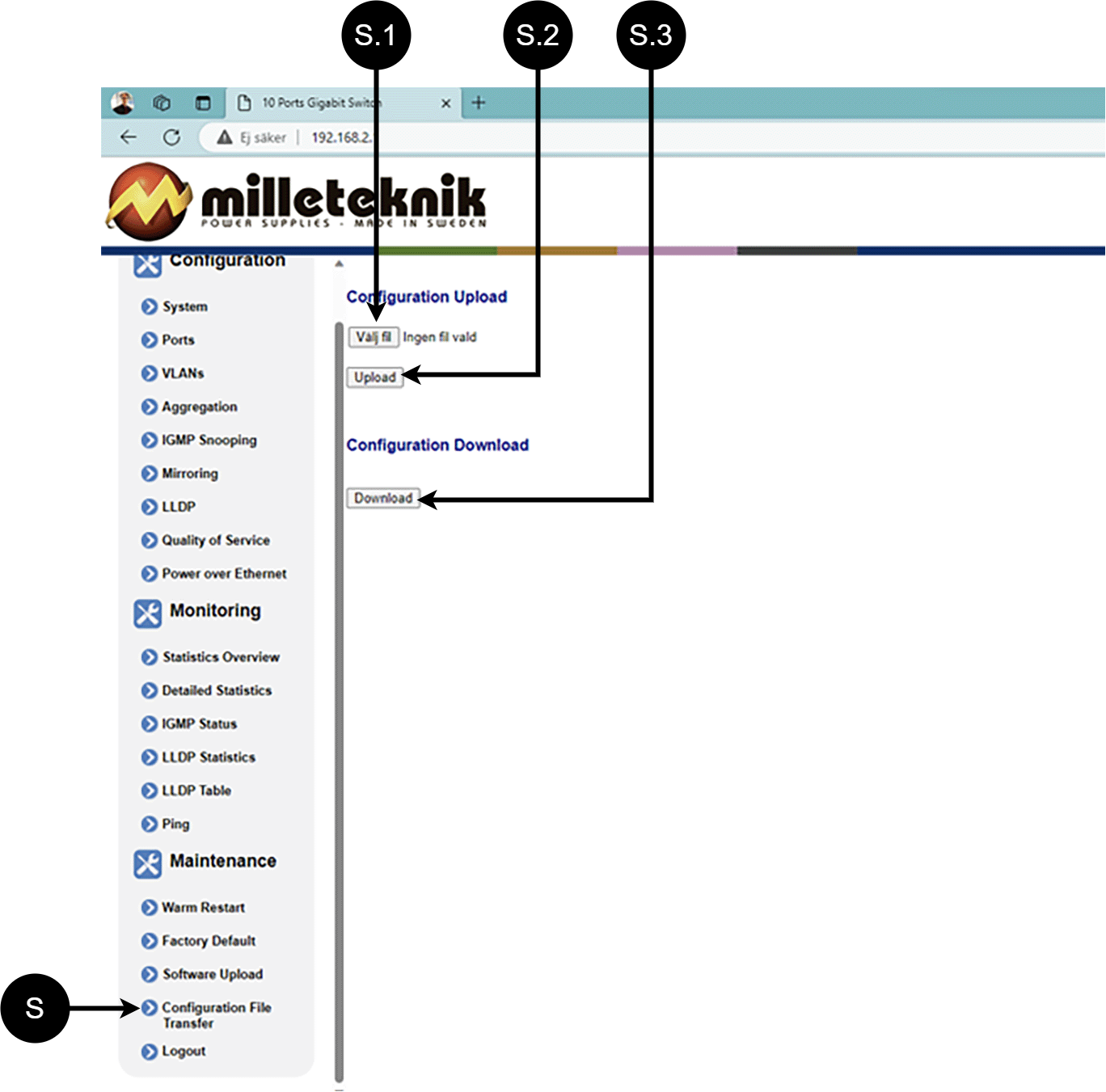
Letter, number | Explanation | ||||||||||||||||||||||||||||||||||||||||||||||||
|---|---|---|---|---|---|---|---|---|---|---|---|---|---|---|---|---|---|---|---|---|---|---|---|---|---|---|---|---|---|---|---|---|---|---|---|---|---|---|---|---|---|---|---|---|---|---|---|---|---|
S | Upload or download the switch's configuration. | ||||||||||||||||||||||||||||||||||||||||||||||||
S.1 | Select new configuration file. | ||||||||||||||||||||||||||||||||||||||||||||||||
S.2 | Upload new configuration file. | ||||||||||||||||||||||||||||||||||||||||||||||||
S.3 | Download configuration file to computer[a]. | ||||||||||||||||||||||||||||||||||||||||||||||||
[a] Newer Windows computers do not allow *.cfg files to be downloaded without additional approval in the browser when downloading. Antivirus programs may delete the file during download. | |||||||||||||||||||||||||||||||||||||||||||||||||
Sign out
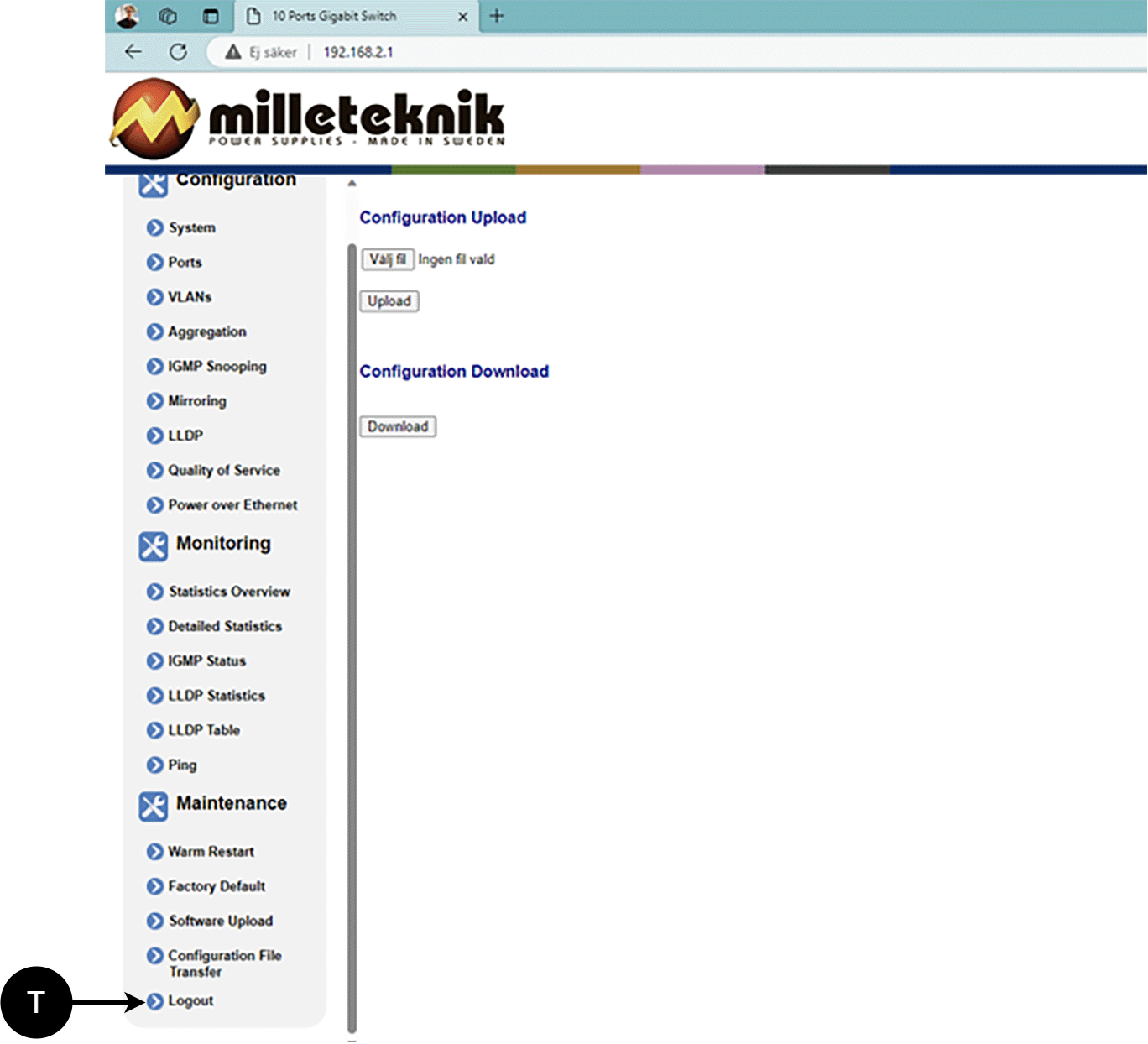
T: Log out of the switch. This does not affect the operation of the switch.
About this information
All information is published subject to possible errors. Information is updated without prior notice. |
Publication date 2024-08-12