Before you begin
Information
Read this first!
Electronics, regardless of enclosure, are intended for use in a controlled indoor environment. Mains voltage should be disconnected during installation.
It is the installer's responsibility that the system is suitable for its intended use. Only authorized persons should install and maintain the system.
All information subject to change.
Instruction manual in Swedish in original[1].
Support
Do you need help with installation or connection? Scan the QR code to read the entire manual.
You will find answers to many questions at: www.milleteknik.se go to your product to read more, download manuals and other product information.
Telephone: +46 31- 340 02 30, e-mail: support@milleteknik.se.
Support is open: Monday-Thursday 08:00-16:00, Fridays 08:00-15:00. Closed 11:30-13:15.
Link to the latest information
Products and software are subject to updates, you will always find the latest information on our website.
Help us make better products
With your help we can develop and produce better products, please fill in our form customer satisfaction survey.
About PoE from Milleteknik
The series is designed to power PoE devices such as access systems, surveillance cameras and other equipment that can be operated with Power over Ethernet. Through its function as a battery backup, the PoE device can continue to be powered in the event of a power failure.
PoE switch 4p M, PoE switch 4p FLX S and PoE switch 4p FLX M are for security systems where a, reliable power supply with battery backup and PoE function is needed. Our PoE have something we call "controlled charging", which is a safety function that means that batteries are not charged with more than 0.5 A. By controlling the charging of batteries, the lifespan of batteries is significantly extended.
The PoE Switch 4p Expansion kit is for expanding the number of PoE ports in PoE switch 4p FLX S and PoE switch 4p FLX M.
How PoE powers devices connected to the power supply
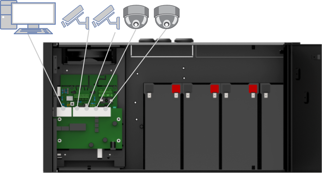 |
PoE can power, for example, surveillance cameras.
Connect external devices to be powered via PoE in ports 1-4.
Connect other devices that do not need to be power supplied with PoE in LAN1-2.
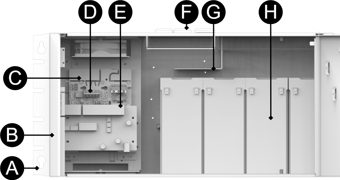
Component overview PoE FLX S
Symbol | Explanation |
|---|---|
A | Brackets, reversible. |
B | Casing in powder-coated sheet metal. |
C | Power supply, (placed on the other side of the motherboard). |
D | Motherboard. |
E | PoE-switch. |
F | Cable entries. |
G | Bracket for Keystone modules. |
H | Space for batteries. |
I | Knockout holes on the back for a larger amount of (PoE) cabling. |
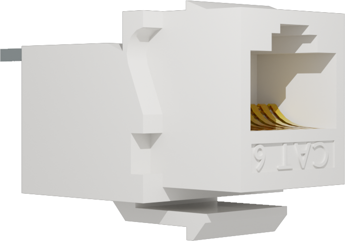
Keystone
A plate for keystone modules makes the installation of PoE devices easier.
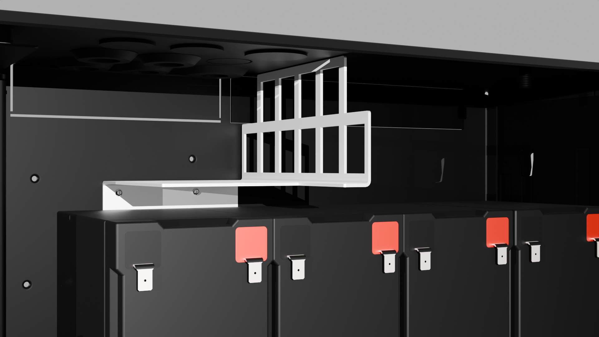
Connection of batteries
Battery wiring is mounted on the circuit board upon delivery. Pictures below only show how to connect wiring.
Place the batteries in the cabinet with the battery terminals facing outwards, against the cabinet door.
Connect the battery cable. Red cable on plus and black cable on minus.
See commissioning for how to start the unit.
If possible, disconnect mains voltage when replacing the battery.
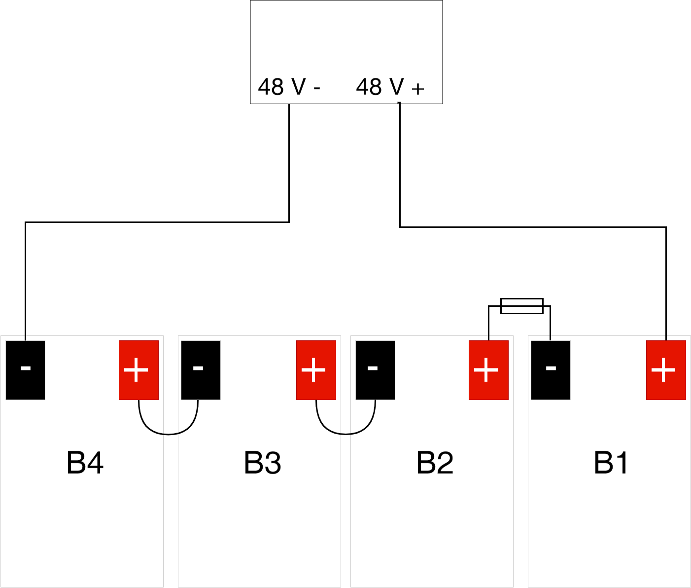 |
Connect the terminals correctly so that you do not damage the equipment.
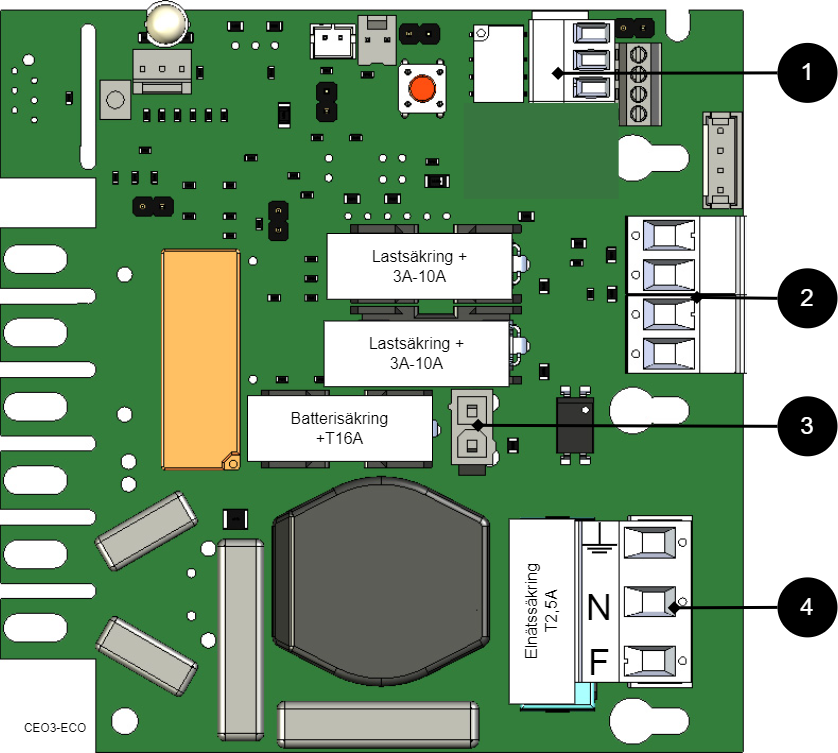
Motherboard - description
See technical data for more information.
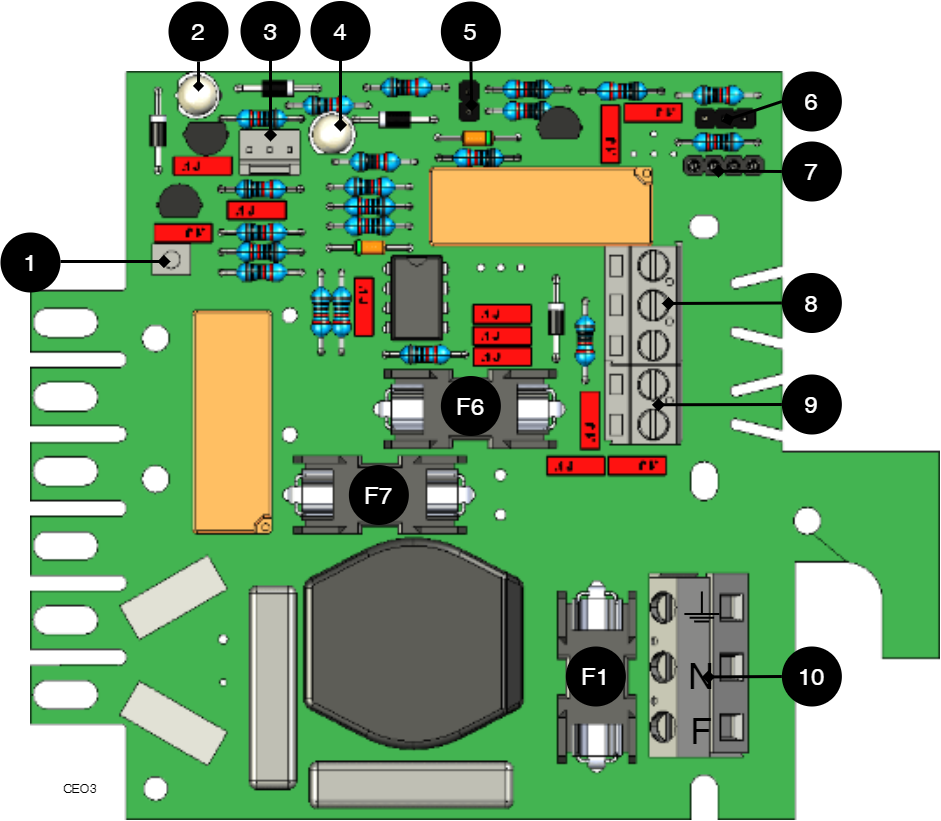 |
The motherboard controls the device and distributes power. See technical data for more information.
No | On the circuit board | Explanation |
|---|---|---|
1 | J24 | Connection for control of power supply. |
2 | D6 | LED 1. |
3 | J11 | connection external LED. |
4 | D11 | LED 2. |
5 | JU2 | Control of alarm threshold. |
6 | JU3 | Connection to external alarm. |
7 | J6 | Connection to buzzer. |
8 | P2:3-5 | Connection to sum alarm. |
9 | P2:1-2 | Load output |
10 | P1:1-3 | Connection to the mains. |
Connect the mains to the motherboard (PCB)
Connect mains
Pull wiring through the cable entry on the cabinet.
If possible, secure the mains cable with cable ties where possible.
Electrical network cabling shall be kept separate from other cabling to avoid EMC interference.
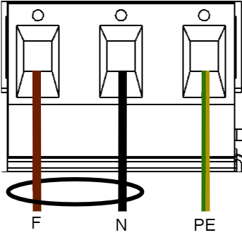
Connect the mains cable to the terminal before it is put back on the motherboard. Secure F and N with cable ties for electrical safety.
Letter | Explanation |
|---|---|
F | Phase |
N | Neutral |
PE | Protective earth |
Electrical mains connection 230 V AC on circuit board
Check that the marking on the circuit board matches the cable arrangement on the terminal block.
Connect load
Max current
The maximum current must not be exceeded. Max current is indicated on nameplate on the device.
Circuit board number | Explanation |
|---|---|
P2: 1 | Connection for load 1 + |
P2: 2 | Connection for load 1 - |
Control alarm limit
Alarm for low battery voltage in battery operation can be controlled.
By jumpering JU2, the limit for when the unit should give an alarm can be lowered.
Alarms are given when the battery voltage in battery drops below the limit.
Short description for PoE switch 4p
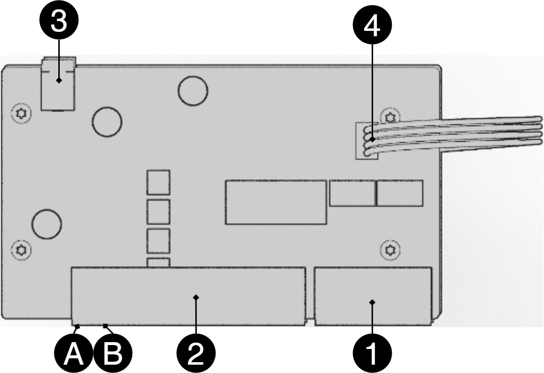 |
No | Terminal no | Explanation |
|---|---|---|
1 | J5 | 2 pcs RJ-45 ports for data, not PoE, (powered). |
2 | J5 | 4 pcs RJ-45 powered ports for connecting PoE devices. |
3 | J2 | Power supply 48 V. |
4 | J8 | Connection for data transmission when additional PoE switch 4p card is connected. |
A | - | Indication, yellow LED lights when data is being transferred. |
B | - | Indication, green LED lights up when device is plugged in. This is only an indication that the port is connected and not the connected device's status. |
Commissioning - how to start the unit
Connect in this order
To minimize the risk of errors that may occur in connection with a short circuit, connections to the motherboard must be made in this order.
Nr | Explanation |
|---|---|
1 | Connect alarm. |
2 | Connect load. |
3 | Connect batteries |
4 | Connect mains. |
Connect batteries.
Connect fuses.
Plug in PoE and other loads.
Screw the mains cable into the terminal and attach the terminal to the motherboard.
Switch on mains voltage.
The unit works normally when the indicator LED on the outside of the cabinet door lights up with a solid green light. See front panel for other status indications.
It may take up to 72 hours before the batteries are fully charged.
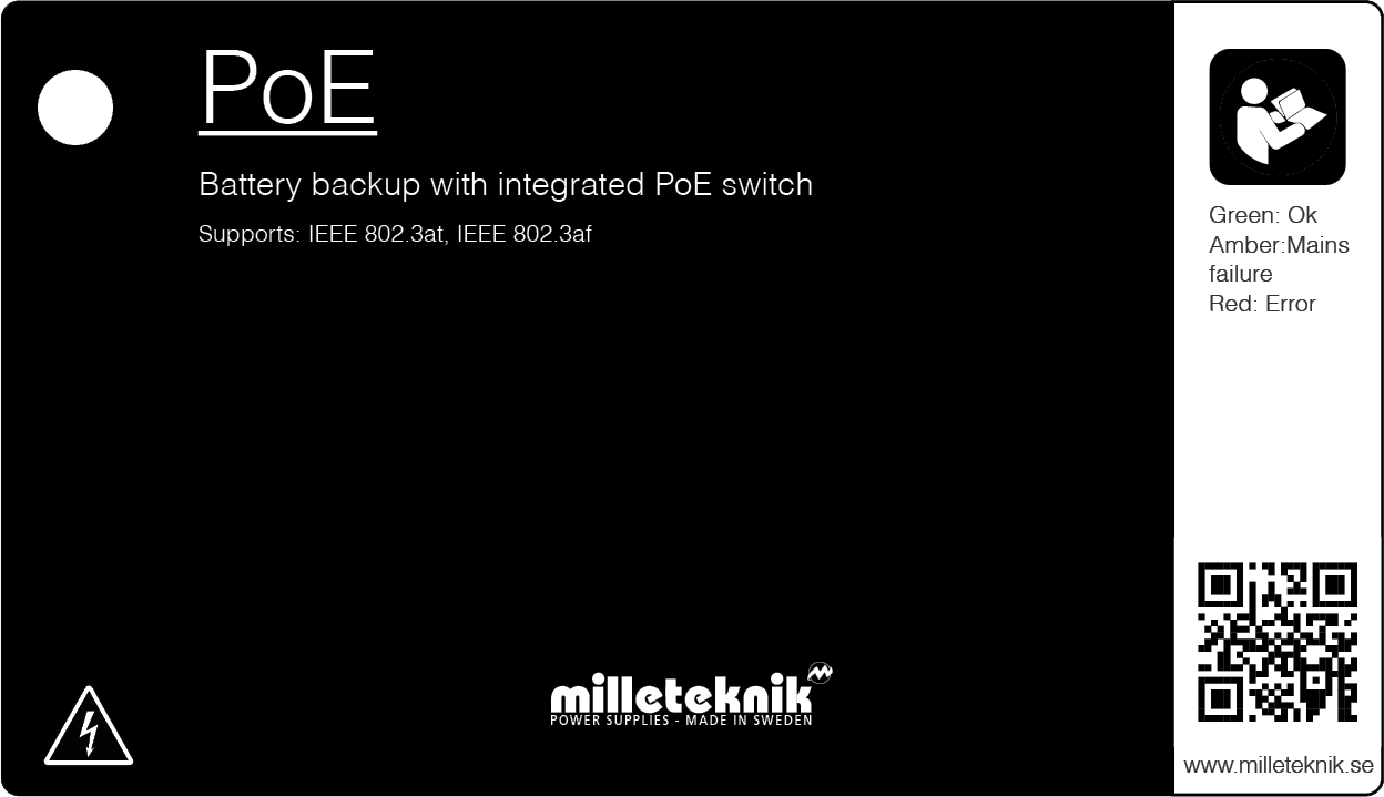
Status indications
Solid green light: Normal operation.
Solid yellow glow: Low battery voltage.
Solid red light: Lights up red when the following three conditions are met (in order): 1. The device goes into battery operation. 2. Fuse trips in battery operation. 3. Batteries have dropped below the alarm limit.
Maintenance
The system with the exception of batteries is maintenance-free when installed in an indoor environment.
battery change
If possible, disconnect mains (voltage) when replacing the battery.
Disconnect battery cables. Note how battery cables are mounted before removing them.
Remove battery fuse between batteries.
Insert and fasten the new batteries.
Connect the battery cables in the same way as before.
Connect battery fuse between batteries.
Switch on mains voltage. The indicator LED may not be green (up to 72 hours), until the batteries are charged.
Test the system by briefly disconnecting the mains voltage, (= the load is driven by the batteries), and then switch on the mains voltage again.
Warranty
The product has a two-year warranty, from the date of purchase (unless otherwise agreed). Support during the warranty period can be reached at support@milleteknik.se or telephone, +46 31-34 00 230. Compensation for travel and / or working hours in connection with locating faults, installing repaired or replaced goods is not included in the warranty. Contact Milleteknik for more information. Milleteknik provides support during the product's lifetime, however, no later than 10 years after the date of purchase. Switching to an equivalent product may occur if Milleteknik deems that repair is not possible. Support costs may (at Milleteknik's discretion) occour after the warranty period has expired.
FAQ - PoE
Product data sheet
PoE
PoE switch with 4 PoE ports.
Technical specifications
These technical specifications are subject to change without notice.
Name, article number and e-number
Name | Article number | E-number (SV) |
|---|---|---|
PoE Switch 4p FLX S | FS01C10048P02504PU | 51 719 52 |
About PoE from Milleteknik
The series is designed to power PoE devices such as access systems, surveillance cameras and other equipment that can be operated with Power over Ethernet. Through its function as a battery backup, the PoE device can continue to be powered in the event of a power failure.
PoE switch 4p M, PoE switch 4p FLX S and PoE switch 4p FLX M are for security systems where a, reliable power supply with battery backup and PoE function is needed. Our PoE have something we call "controlled charging", which is a safety function that means that batteries are not charged with more than 0.5 A. By controlling the charging of batteries, the lifespan of batteries is significantly extended.
The PoE Switch 4p Expansion kit is for expanding the number of PoE ports in PoE switch 4p FLX S and PoE switch 4p FLX M.
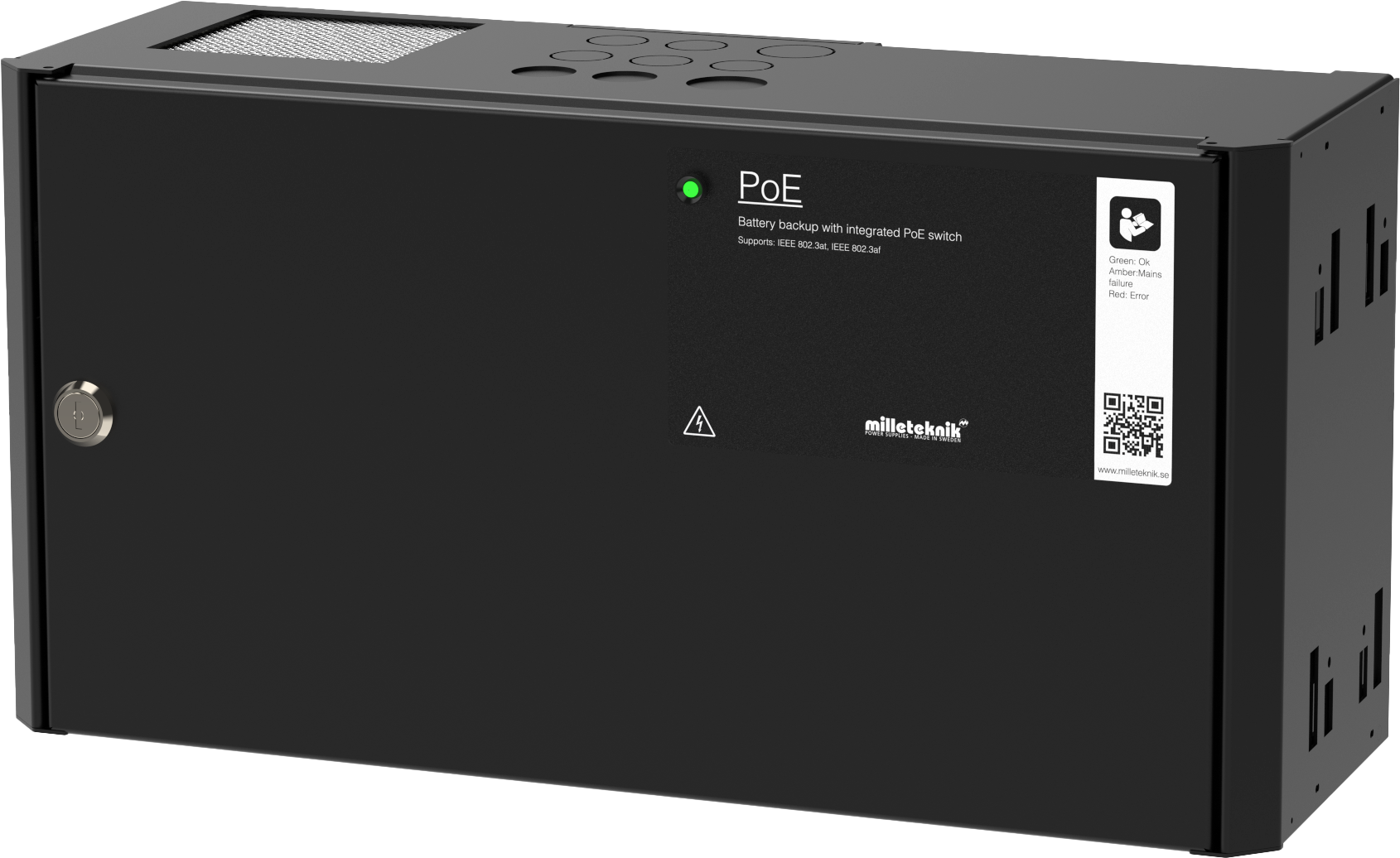
PoE switch 4p FLX S
Power supply with backup power to power PoE devices such as surveillance cameras and other PoE powered devices. The power supply has batteries that keep powering on when the power grid goes down. Long life, energy efficient and support is available if something goes wrong, now or in 10 years.
Power over Ethernet from Milleteknik
PoE for security applications with the need for power supply with backup power.
Proven, reliable technology.
For fixed installation.
Swedish made.
Limitations
Important
Note that 802.3at type2 is not supported, as the PoE card lacks a handshake function for type 2. Read more.
The product is tested and verified against Axema access systems and Dinbox access systems and is therefore recommended for use only with these systems. The product is currently not recommended for other products that have an af/at handshake procedure. The product deviates from standard IEEE 802.3af per port and IEEE 802.3at as the power is modified to be used together with Axema passer system and Dinbox passer system, which leads to shortcomings, (PoE-connected product does not start), against products that require handshake.
Areas of use
Power supply for camera surveillance and other applications that can be powered by PoE.
Security applications powered by PoE that need backup power in the event of a power outage.
Alarm
The device alarms for:
Low battery voltage, low battery voltage in the event of a broken fuse on the load output.
Fixed installation
The product is intended for fixed installation. The battery backup must be installed by a qualified installer.
Battery types
The ECO series can be used with AGM batteries. Do not mix types of batteries, brand or used and new batteries.
Regulations and certifications
Requirements that the product meets
EMC: | EMC Directive 2014 / 30EU |
Electricity: | Low voltage directive: 2014/35 / EU |
PoE: | IEEE 802.3af, IEEE 802.3at/30.8 W Note that 802.3at type2 is not supported, as the PoE card lacks a handshake function for type 2. |
CE: | CE directive according to: 765/2008 |
Emission: | EN61000-6-: 2001 EN55022: 1998: -A1: 2000, A2: 2003 Klass B, EN61000-3-2: 2001 EN55022 (CISPR22), GB9254 Class B, EN55014, EN61000-3-2Class A( 75% Load),EN61000-3-3 |


Expected operating time in the event of a power failure ( with new batteries)
PoE | Battery | Power 15.4 W | Power 30.8 W | Power 62 W | Power 90 W | Power 100 W | Power 120 W | Power 180W | Power 240 W |
|---|---|---|---|---|---|---|---|---|---|
PoE switch 4p FLX S (48 V) | 4 pcs 7.2 Ah | 18 h 30 min. | 8 h 30 min. | 3 h 45 min. | - | 2 h 10 min. | 1 h 45 min. | - | - |
Circuit boards - Technical data
Technical data: CEO 3
Info | Explanation |
|---|---|
Article title | CEO3 |
Product description | CEO 3 is the next generation circuit board for simpler battery backups. Advanced functions that were not previously possible in simpler battery backups are now available as standard. CEO 3 is a reliable heart in simpler battery backups with fewer components than before, which reduces the environmental impact. |
Measure | 120 x 55 mm x 52 mm |
Own consumption | 32 mA |
Fuse on output | F1: T2.5A, mains fuse. F6: T5A, load fuse +, P2:1. F7: T16A, battery fuse. |
Outputs | One cargo outlet, fused. |
Insurance | Load output: + secured. |
Alarm via | Triggered load securing, potential-free shifting. Conclusion CO / NO. PRO1: Via alarm terminal J13 (NC-CO). PRO2: Via alarm terminal J13 (NC-CO). PRO2 v3: Via J11 and J12 to motherboard on to the parent system. PRO 3: Via J11 and J12 to motherboard on to the parent system. |
Protection against: | Deep discharge, short circuit, overload and overvoltage. |
Indicator diode | Green | Orange | RED |
|---|---|---|---|
(2) / D2 | OK | Low battery voltage / fuse fault. | Low battery voltage with broken fuse on output. |
(4) / D11 | - | Overvoltage. | Batteries incorrectly connected. |
Alarm limit at low battery voltage | 48 V |
|---|---|
(5) / JU2 with jumper | 47 V |
(5) / JU 2 without jumper | 51 V |
The unit is delivered without a jumper on (8) / JU2 | |
sum alarm | |
|---|---|
(8) P2: 3 | NO |
(8) P2: 4 | CO |
(8) P2: 5 | NC |
Technical data: PoE card
Limitations
Important
Note that 802.3at type2 is not supported, as the PoE card lacks a handshake function for type 2. Read more.
The product is tested and verified against Axema access systems and Dinbox access systems and is therefore recommended for use only with these systems. The product is currently not recommended for other products that have an af/at handshake procedure. The product deviates from standard IEEE 802.3af per port and IEEE 802.3at as the power is modified to be used together with Axema passer system and Dinbox passer system, which leads to shortcomings, (PoE-connected product does not start), against products that require handshake.
Product | Number of PoE / LAN ports | Max power per port | PoE, continuous power | Ethernet type | Network ports | Interface | Functions | Type, injector and switch |
|---|---|---|---|---|---|---|---|---|
PoE Switch 4p FLX S | 4/2 | 30,8 @ 54,6 V DC | 150 W | Fast Ethernet Mbit PoE switch | 10 / 100 PoE | 1000Base-T RJ-45 | Auto-negotiation, Auto-uplink (auto MDI/MDI-X) | Unmanaged. There is no software interface to control the switch. |
Power supply
Power supply - Technical Data LRS-150-48
Info | Explanation |
|---|---|
Output voltage | 54.6 V |
Output current | 0 A - 3.3 A |
Output voltage, ripple | 200 mVp-p |
Overvoltage | 55.2 V - 64.8 V |
Voltage recharge, ripple / current limitation | Less than 0.6 Vp-p |
Efficiency | 90% |
Current limitation | 110% - 140% |
Constant voltage | +/- 0.5% |
Regulatory accuracy | * / - 1.0% |
Input current (230 V) | 1.7 A |
Mains voltage frequency | 47 Hz- 63 Hz |
Mains voltage | 230 V AC - 240 V AC |
Brand effect | 158.4 W |
Temperature range | -30°C - +70°C |
Humidity range | 20% - 90% RH non-condensed |
Technical data enclosures
Enclosures - Technical Data FLX S
Info | Explanation |
|---|---|
Name | FLX S |
Enclosure class | IP 32 |
Measure | Height: 222 mm, width 437 mm, depth 145 mm |
Height units | 5 HE |
Mounting | Wall or 19 "rack |
Ambient temperature | + 5 ° C - + 40 ° C. For best battery life: + 15 ° C to + 25 ° C. |
Environment | Environmental class 1, indoors. 20% ~ 90% relative humidity |
Material | Powder coated sheet |
Color | Black |
Cable entries, number | 4 |
Batteries that fit | 2 pcs 7.2 Ah or 4 pcs 7.2 Ah. |
Place for fan | Yes |
Link to the latest information
Products and software are subject to updates, you will always find the latest information on our website.
Warranty, support, country of manufacture and country of origin
Warranty
The product has a two-year warranty, from the date of purchase (unless otherwise agreed). Support during the warranty period can be reached at support@milleteknik.se or telephone, +46 31-34 00 230. Compensation for travel and / or working hours in connection with locating faults, installing repaired or replaced goods is not included in the warranty. Contact Milleteknik for more information. Milleteknik provides support during the product's lifetime, however, no later than 10 years after the date of purchase. Switching to an equivalent product may occur if Milleteknik deems that repair is not possible. Support costs may (at Milleteknik's discretion) occour after the warranty period has expired.
Support
Do you need help with installation or connection?
You will find answers to many questions at: www.milleteknik.se/support
Phone: +46 31-340 02 30
Support is open: Monday-Thursday 08:00-16:00, Fridays 08:00-15:00. Closed 11:30-13:15.
Spare parts
Contacted support for questions about spare parts.
Support after the warranty period
Milleteknik provides support during the life of the product, but no longer than 10 years after the date of purchase. Replacement for an equivalent product may occur if the manufacturer deems that repair is not possible. Costs for support and replacement are added after the warranty period has expired.
Questions about product performance?
Contact sales: 46 31-340 02 30, e-mail: sales@milleteknik.se
Country of manufacture
Country of manufacture / country of origin is Sweden. For more information, contact your seller.
Designed and produced by: Milleteknik AB
Designed and produced by Milleteknik AB
Batteries - recommended, not included
Batteries are not included they are sold separately
Batteries are sold separately.
7.2 Ah, 12 V AGM battery
Fits in | Number of batteries |
|---|---|
PoE switch 4p FLX S | 4 |
Battery type | V | Ah |
|---|---|---|
Maintenance-free AGM, lead-acid battery. | 12 V | 7.2 Ah |
Article number | E-number | Article name | Terminal | Measure. Height width depth | Weight per piece | Make |
|---|---|---|---|---|---|---|
MT113-12V07-01 | 5230536 | UPLUS 12V 7.2Ah 10+ Design Life battery | Flat pin 6.3 mm | 151 x 65 x 100 mm. | 2.4 kg | UPLUS |
Product life cycle, environmental impact and recycling
The product is designed and constructed for a long service life, which reduces the environmental impact. The product's service life depends on, among other things, environmental factors, mainly ambient temperature, unforeseen load on components such as lightning strikes, external damage, handling errors, and more. Products are recycled by being handed over to the nearest recycling station or sent back to the manufacturer. Contact your distributor for more information. Costs that arise in connection with recycling are not reimbursed.

Address and contact details
Milleteknik AB |
Ögärdesvägen 8 B |
S-433 30 Partille |
Sweden |
+46 31 340 02 30 |
info@milleteknik.se |
www.milleteknik.com |
[1] Translations in languages other than Swedish are only indicative and have not been verified. Translation must always be checked against the Swedish original to ensure correct information.