Before you begin
Information
Read this first!
Electronics, regardless of enclosure, are intended for use in a controlled indoor environment.
Ventilation must not be covered.
Only authorized persons should install and maintain the system.
It is the installer's responsibility to ensure that the system is suitable for its intended use.
Documents accompanying the system must be kept in or in its immediate vicinity.
Mains voltage should be disconnected during installation.
All information subject to change.
Upon installation of this product, the installer acknowledges and accepts the limitations of this product as described in this manual.
Instruction manual in Swedish in original[1].
Support
Phone: +46 31-340 02 30
You will find answers to many questions at: www.milleteknik.se/support
Telephone: +46 31- 340 02 30, e-mail: support@milleteknik.se.
Support is open: Monday-Thursday 08:00-16:00, Fridays 08:00-15:00. Closed 11:30-13:15.
Link to the latest information
Products and software are subject to updates, you will always find the latest information on our website.
Help us make better products
With your help we can develop and produce better products, please fill in our form customer satisfaction survey.
About PoE from Milleteknik
The series is designed to power PoE devices such as access systems, surveillance cameras and other equipment that can be operated with Power over Ethernet. Through its function as a battery backup, the PoE device can continue to be powered in the event of a power failure.
PoE switch 4p M, PoE switch 4p FLX S and PoE switch 4p FLX M are for security systems where a, reliable power supply with battery backup and PoE function is needed. Our PoE have something we call "controlled charging", which is a safety function that means that batteries are not charged with more than 0.5 A. By controlling the charging of batteries, the lifespan of batteries is significantly extended.
The PoE Switch 4p Expansion kit is for expanding the number of PoE ports in PoE switch 4p FLX S+ and PoE switch 4p FLX M+.
How PoE powers devices connected to the power supply
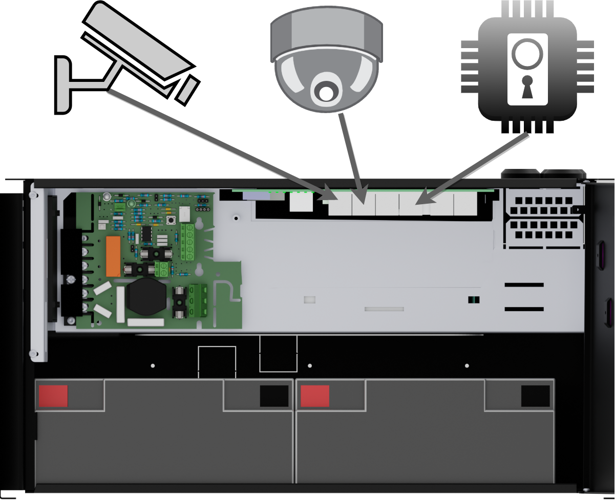 |
PoE can power, for example, surveillance cameras.
Connect external devices to be powered via PoE in PoE ports.
Connect other devices that do not need to be power supplied in LAN ports.
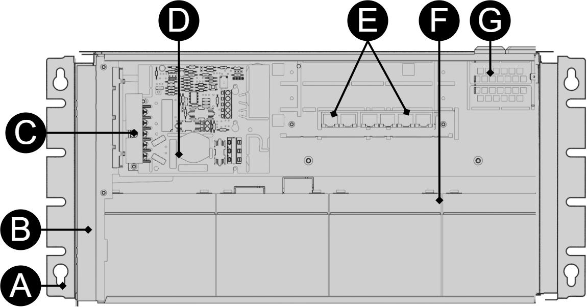
Component overview PoE FLX M
 |
Symbol | Explanation |
|---|---|
A | Brackets, reversible. |
B | Casing in powder-coated sheet metal. |
C | Power supply, (placed under the motherboard). |
D | Motherboard. |
E | Three places for PoE switches. One PoE switch is installed from the factory. Four PoE ports are on the left and two LAN ports are on the right. |
F | Room for batteries. |
G | Cable entries. |
Mounting on a wall or in a 19 "rack
The unit can be mounted in a 19 ”rack or on a wall. The included brackets can be attached in two ways: When mounting on a wall, the brackets must sit backwards, against the wall. When mounting in a 19 ”rack, the console must be at the front edge of the unit.
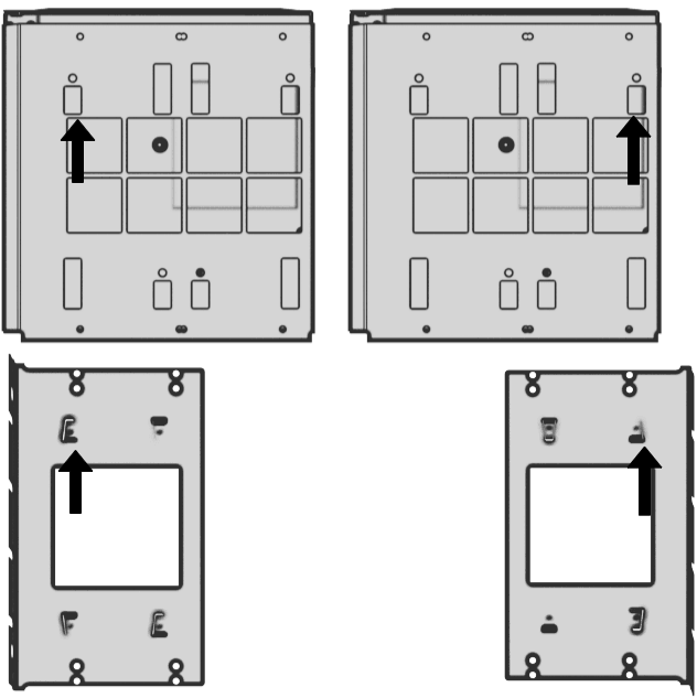
Left bracket facing the front for mounting in a 19 "rack.
Right bracket facing the back for wall mounting.
Important
Leave 100 mm free around the air vents.
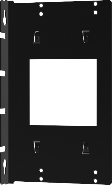
Console for FLX M and FLX L
Bracket is reversible and can be mounted in two ways. It comes with brackets in to the device.
Two consoles must be used for FLX M.
 |
Connection of batteries
Battery wiring is mounted on the circuit board upon delivery. Pictures below only show how to connect wiring.
Place the batteries in the cabinet with the battery terminals facing outwards, against the cabinet door.
Connect the battery cable. Red cable on plus and black cable on minus.
If possible, disconnect mains voltage when replacing the battery.
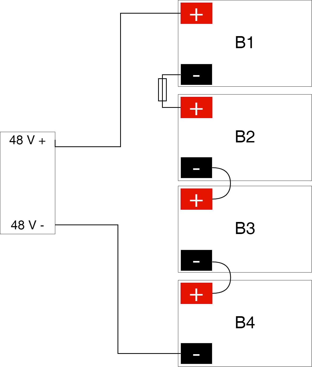 |
Connect the terminals correctly so that you do not damage the equipment.
Motherboard - description
See technical data for more information.
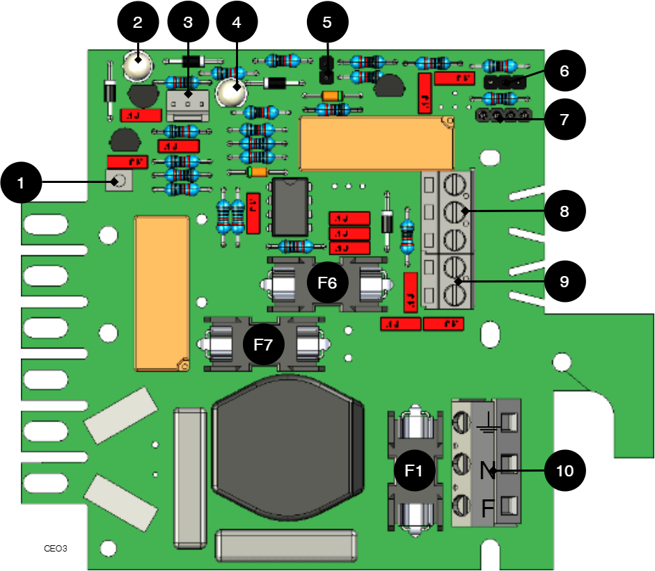 |
The motherboard controls the device and distributes power. See technical data for more information.
No | On the circuit board | Explanation |
|---|---|---|
1 | J24 | Connection for control of power supply. |
2 | D6 | LED 1. |
3 | J11 | connection external LED. |
4 | D11 | LED 2. |
5 | JU2 | Control of alarm threshold. |
6 | JU3 | Connection to external alarm. |
7 | J6 | Connection to buzzer. |
8 | P2:3-5 | Connection to sum alarm. |
9 | P2:1-2 | Load output |
10 | P1:1-3 | Connection to the mains. |
Connect the mains to the motherboard (PCB)
Connect mains
Pull wiring through the cable entry on the cabinet.
If possible, secure the mains cable with cable ties where possible.
Electrical network cabling shall be kept separate from other cabling to avoid EMC interference.
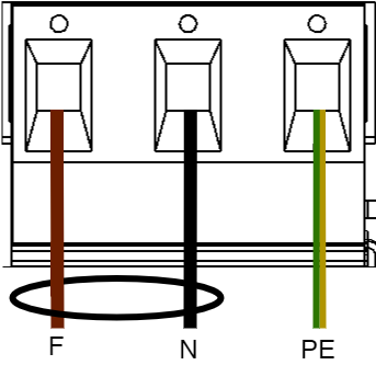
Connect the mains cable to the terminal before it is put back on the motherboard. Secure F and N with cable ties for electrical safety.
Letter | Explanation |
|---|---|
F | Phase |
N | Neutral |
PE | Protective earth |
Electrical mains connection 230 V AC on circuit board
Check that the marking on the circuit board matches the cable arrangement on the terminal block.
Connect load
Max current
The maximum current must not be exceeded. Max current is indicated on nameplate on the device.
Circuit board number | Explanation |
|---|---|
P2: 1 | Connection for load 1 + |
P2: 2 | Connection for load 1 - |
Control alarm limit
Alarm for low battery voltage in battery operation can be controlled.
By jumpering JU2, the limit for when the unit should give an alarm can be lowered.
Alarms are given when the battery voltage in battery drops below the limit.
Short description for PoE switch 4p
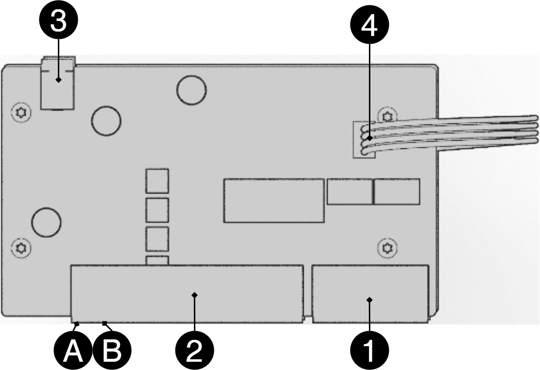 |
No | Terminal no | Explanation |
|---|---|---|
1 | J5 | 2 pcs RJ-45 ports for data, not PoE, (powered). |
2 | J5 | 4 pcs RJ-45 powered ports for connecting PoE devices. |
3 | J2 | Power supply 48 V. |
4 | J8 | Connection for data transmission when additional PoE switch 4p card is connected. |
A | - | Indication, yellow LED lights when data is being transferred. |
B | - | Indication, green LED lights up when device is plugged in. This is only an indication that the port is connected and not the connected device's status. |
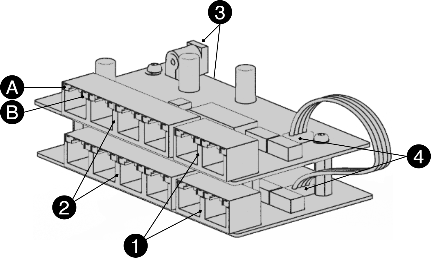 |
Two cards are connected with cable on 4, or a patch cable between 1 on each card.
The picture shows how cards sit on top of each other in the PoE switch 4p FLX S+. In the PoE switch 4p FLX M+, the cards are connected separately in mounting plate.
How the PoE switch software is accessed
How the software is accessed in the PoE Switch
This section shows how to log in to the switch's configuration web page.
In order to configure the software in the switch, access to the switch requires the correct IP address to be set on the computer.
Access to the switch's software is through a browser (Chrome, Edge, Firefox).
Follow the steps to access the switch's settings.
Note
The settings shown are settings for PC, (Windows 7 - Windows 11). Windows and names may vary between different versions of Windows. Unfortunately, we cannot provide support for settings of your computer.
Notice
The address of the PoE switch is: 192.168.2.1 and username and password are: admin/admin The IP address in the switch is static (fixed) and therefore the computer's IP address and subnet mask must be static.
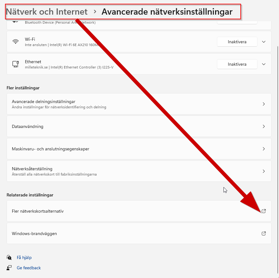
Open settings and go to Network and Internet -> Advanced network settings. Open more network card options.
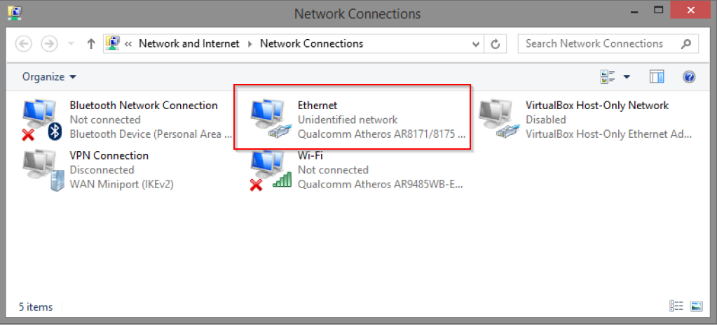
A Network Connections window will appear showing all available network connections on the computer. Double-click the network connection you use to connect to the switch.
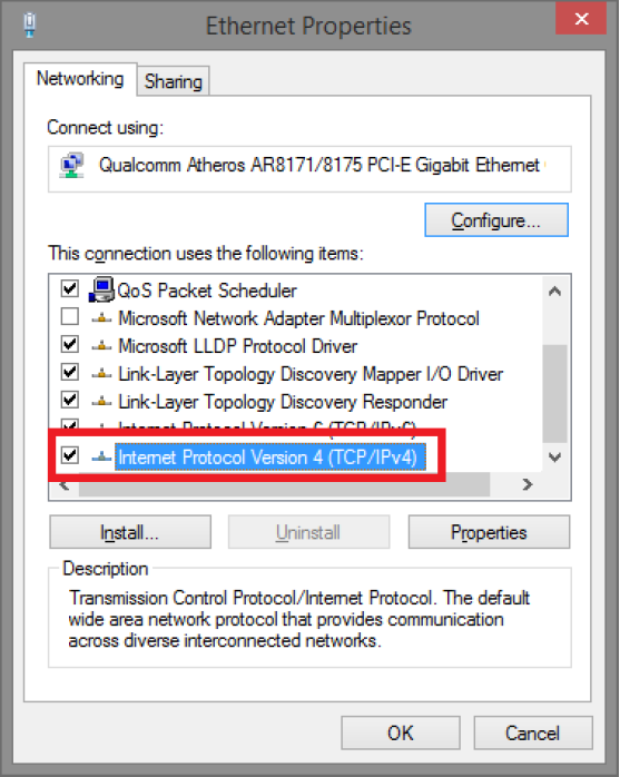
Ethernet status window appears. click the button Characteristics as shown in the figure below.
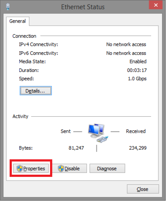
Double-click Internet Protocol Version 4 (TCP / IPv4).
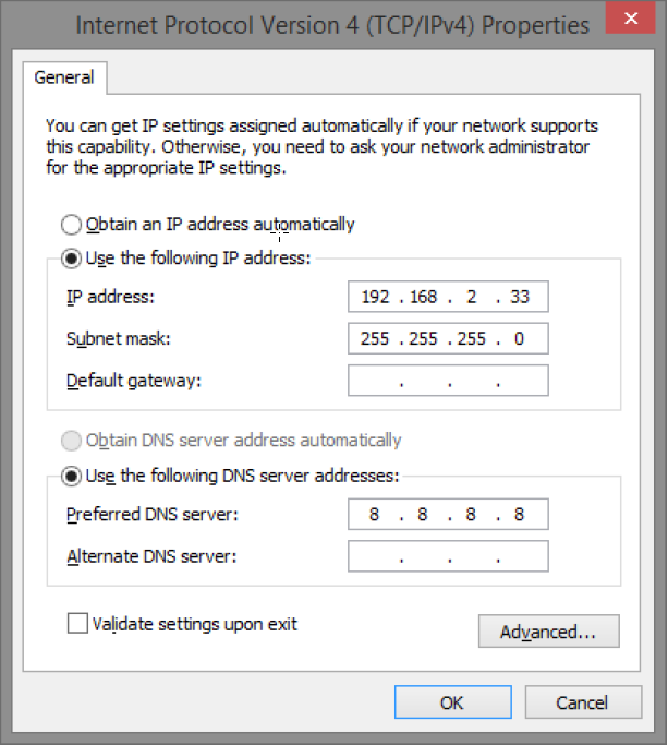
Set the computer's IP address and subnet mask as shown in the figure below. By default, the product's IP address be 192.168.2.1. You can set any IP address as long as it is not the same as your switch's IP address and is in the same network segment as your switch's IP address. Press OK to apply the TCP/IPv4 settings you just made. Now you can connect to your switch using a web browser (Chrome, Edge or Firefox).
Connect an RJ-45 cable and connect to the PoE switch.
Log in to the PoE switch
Note
IP address of the switch (factory setting): 192.168.2.1
Password (factory setting): admin
Start the browser on your computer.
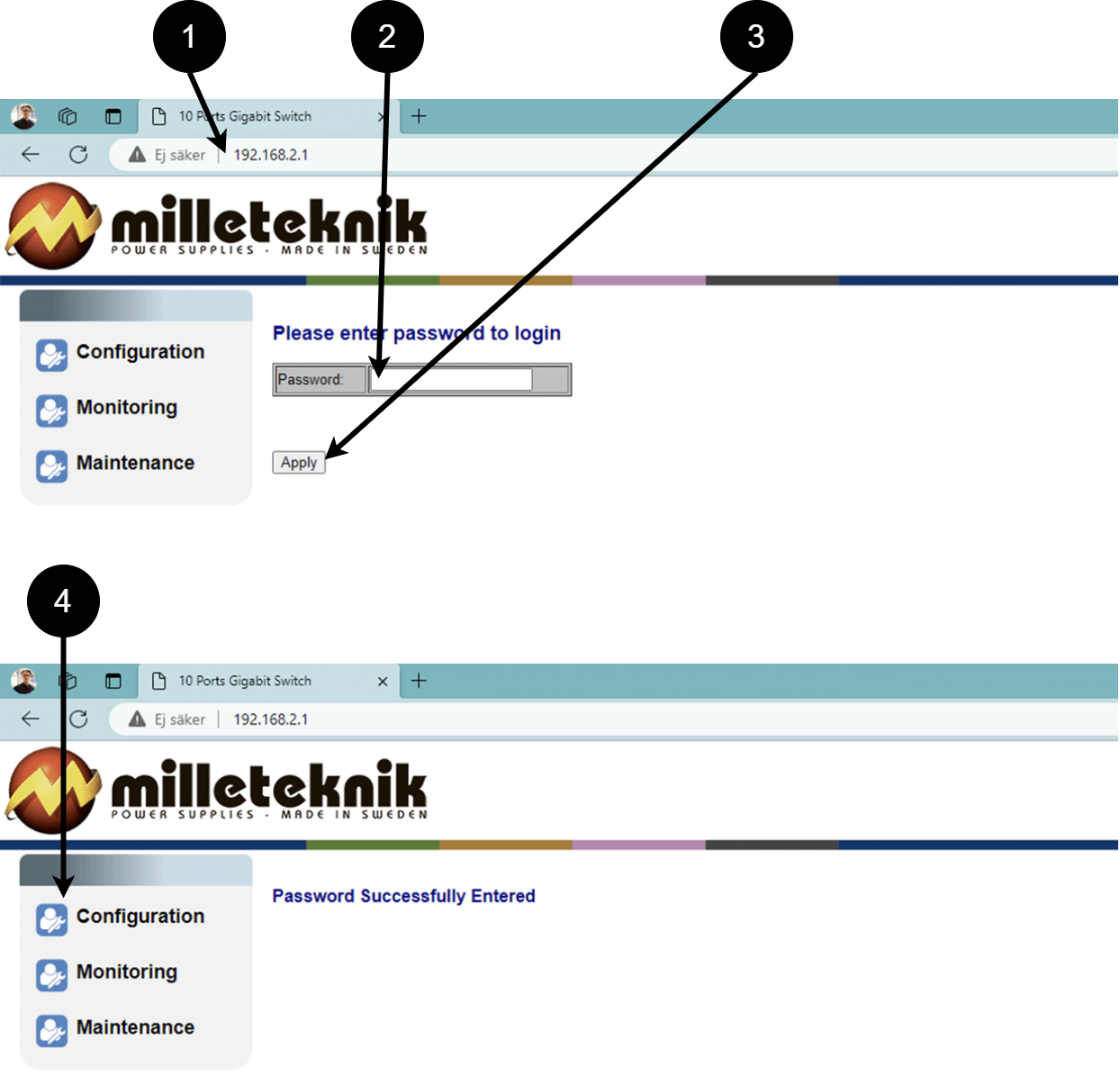
Login to PoE switch.
Number
Explanation
1
IP address of the PoE switch: 192.168.2.1
2
Password: admin
3
Apply = Ok
4
Menu in the PoE switch
Configuration
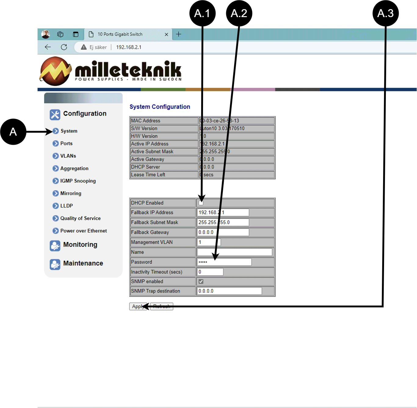
System, configuration
Letter, number | Explanation |
|---|---|
A | PoE switch system configuration page |
A.1 | Tick here if you are going to use DHCP, see warning below. |
A.2 | Changes the factory default password, (admin). |
A.3 | If you have made any changes, you need to click "Apply" to save the changes. |
Ports, configuration
Letter, number | Explanation |
|---|---|
B | Gates |
B.1 | This setting normally does not need to be changed. Select the speed of the PoE switch's ports. |
B.2 | This setting normally does not need to be changed. |
VLAN configuration
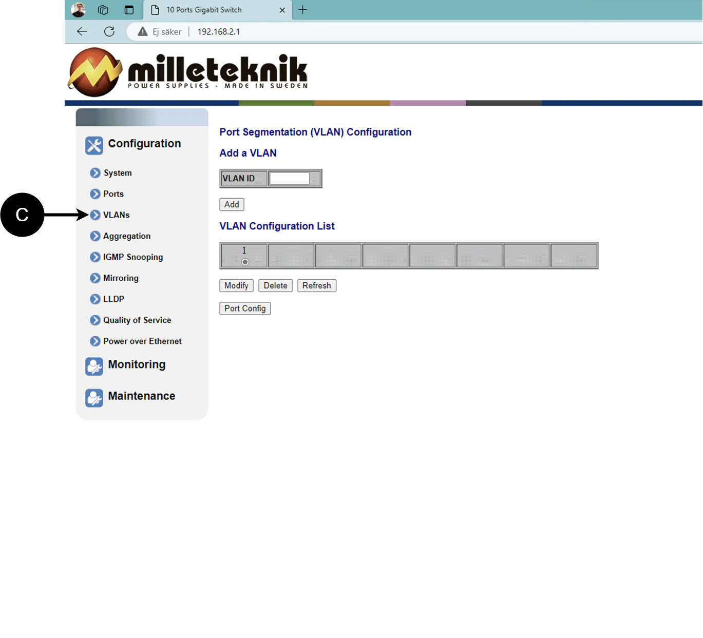
Configuration of Virtual LAN.
Aggregation, configuration
Load balancing between the ports.
IGMP Snooping, configuration
Switch that controls reception.
Mirroring, configuration
Mirroring of ports.
LLDP configuration
Letter, number | Explanation |
|---|---|
G | LLDP stands for "Link Layer Discovery Protocol", which is a network protocol standard used to discover and communicate information about network devices connected to the same Ethernet network. The protocol allows devices such as switches and routers to send and receive messages containing information about the device's identification, capabilities, and connection topology. |
G.1 | RX and TX are abbreviations used in electronics, communications, and computer networking to indicate the direction of data flow between devices. RX: The abbreviation "RX" stands for "Receive" or "Reception". It indicates that the device is receiving data or signals from another device. When a device has an RX input, it means that it is designed to receive data or information from a transmitting device. TX: The abbreviation "TX" stands for "Transmit" or "Transmission". It indicates that the device is transmitting data or signals to another device. If a device has a TX output, it means that it is designed to transmit data or information to a receiving device. These abbreviations are especially common when it comes to data communication, such as in the context of network cables where there are specific RX and TX wires that allow for two-way communication between devices. |
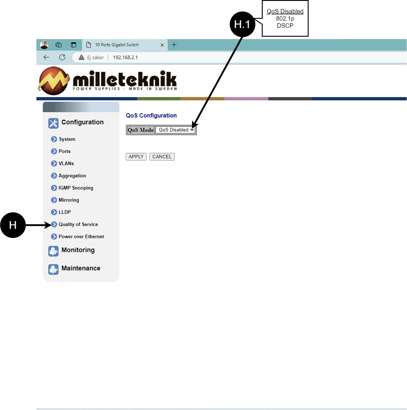
QoS, configuration
Letter, number | Explanation |
|---|---|
H | QoS gives different network traffic different priority depending on its importance and requirements, helping to ensure that important services are delivered with sufficient bandwidth and minimal delay even when the network is under load. |
H.1 | Sets whether QoS is active. |
PoE, configuration
Letter, number | Explanation |
|---|---|
I | Power over Ehternet |
I.1 | Turns PoE port on or off. Don't forget to press "Apply" to save changes. |
Monitoring
Statistics, overview
Letter, number | Explanation |
|---|---|
J | Statistics, overview |
J.1 | Traffic per port. |
Statistics, detailed
Letter, number | Explanation |
|---|---|
K | Detailed statistics |
K.1 | Select the port for which you want statistics. |
IGMP status
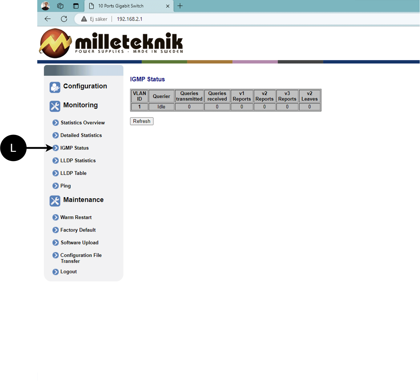
L: Status of IGMP
LLDP statistics
M: LLDP statistics
LLDP table
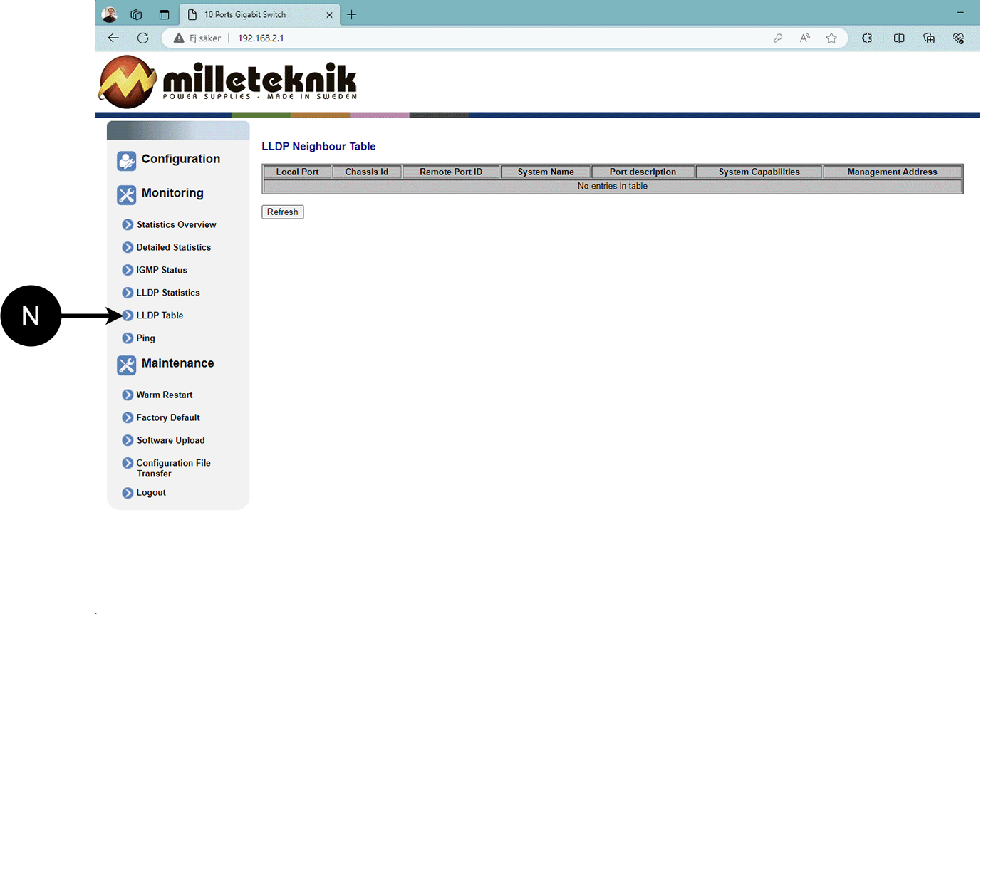
N: LLDP overview.
Ping
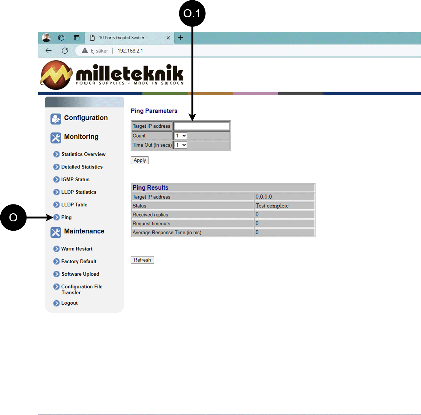
Letter, number | Explanation |
|---|---|
O | Ping |
0.1 | Input address to test the connection and response time. |
Maintenance
Reboot
Warning
Restart is done by PoE switch, battery backup is not restarted. Upon reboot, connected devices will lose connection. Alarm can be set to battery backup, but it disappears when the PoE switch is back on.

Letter, number | Explanation |
|---|---|
P | Rebooting the PoE switch. |
P.1 | Select "Yes" to reboot the switch. |
Factory reset
Warning
Factory reset is done by PoE switch. Battery backup is not restored. On reset, connected devices will lose connection. Alarm can be set to battery backup, but it disappears when the PoE switch is back on.
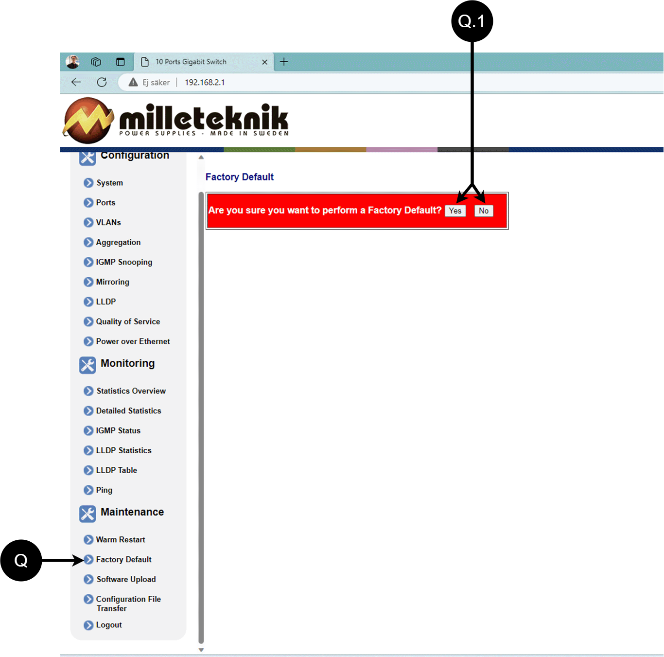
Letter, number | Explanation |
|---|---|
Q | Factory reset the PoE switch. |
Q.1 | Select "Yes" to factory reset the PoE switch. |
Upload new software
Warning
Only use software you received from Milleteknik's support. Milleteknik assumes no responsibility for software or consequences such as damage to the device or peripherals or other damage that may arise from uploading unapproved software.
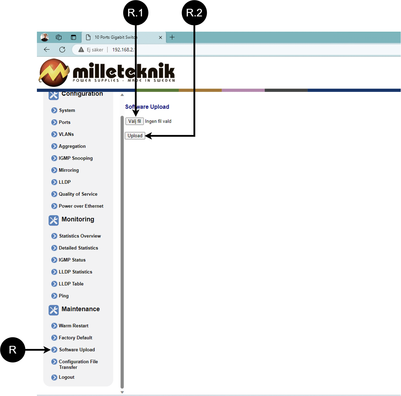
Letter, number | Explanation |
|---|---|
R | Upload new software to the Switch. |
R.1 | Navigate to the computer where you saved the file. |
R.2 | Click "Upload" to upload the software. |
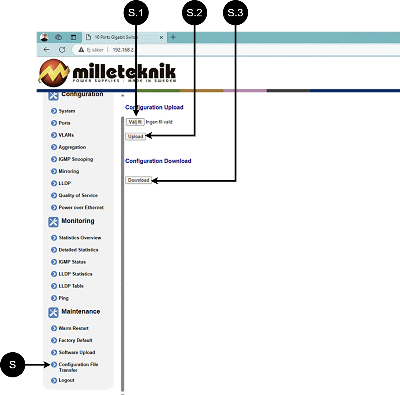
Load and save configuration file
Letter, number | Explanation | ||||||||||||||||||||||||||||||||||||||||||||||||
|---|---|---|---|---|---|---|---|---|---|---|---|---|---|---|---|---|---|---|---|---|---|---|---|---|---|---|---|---|---|---|---|---|---|---|---|---|---|---|---|---|---|---|---|---|---|---|---|---|---|
S | Upload or download the switch's configuration. | ||||||||||||||||||||||||||||||||||||||||||||||||
S.1 | Select new configuration file. | ||||||||||||||||||||||||||||||||||||||||||||||||
S.2 | Upload new configuration file. | ||||||||||||||||||||||||||||||||||||||||||||||||
S.3 | Download configuration file to computer[a]. | ||||||||||||||||||||||||||||||||||||||||||||||||
[a] Newer Windows computers do not allow *.cfg files to be downloaded without additional approval in the browser when downloading. Antivirus programs may delete the file during download. | |||||||||||||||||||||||||||||||||||||||||||||||||
Log out
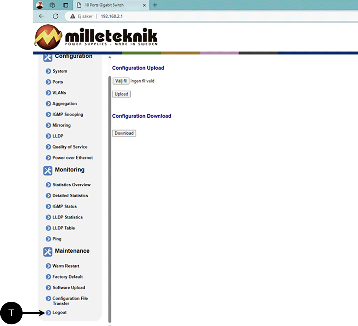
T: Log out of the switch. This does not affect the operation of the switch.
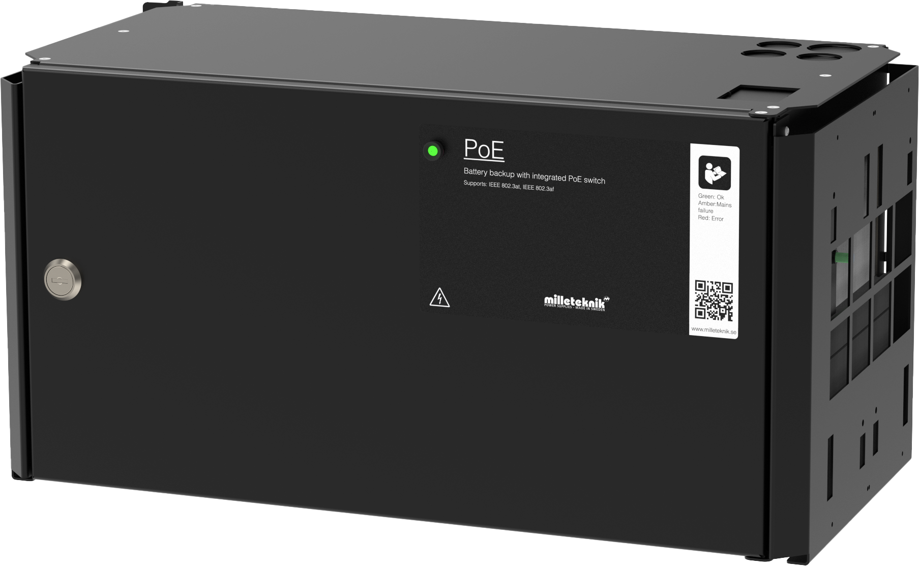
Commissioning - how to start the unit
The unit works normally when the indicator LED on the outside of the cabinet door lights up with a solid green light. See front panel for other status indications.
It may take up to 72 hours before the batteries are fully charged.
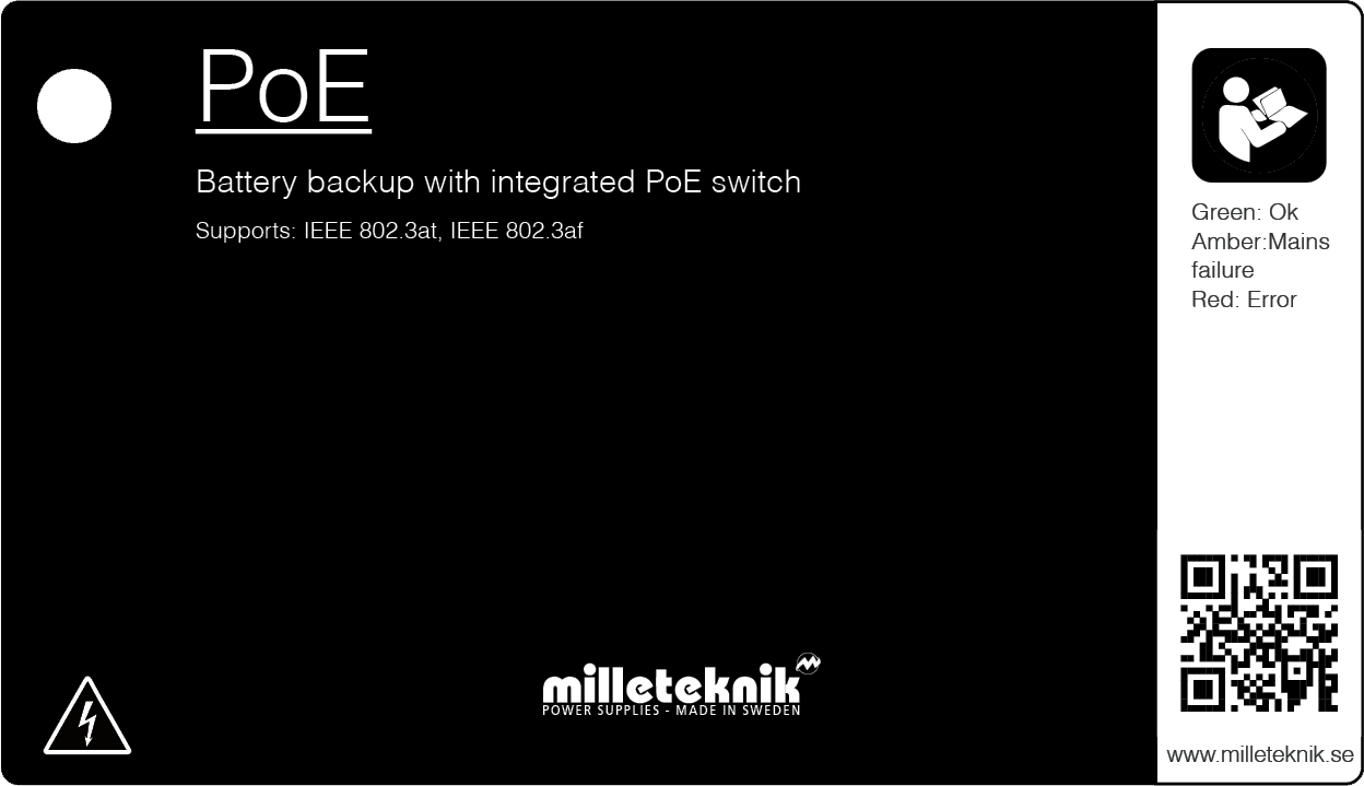
Status indications
Solid green light: Normal operation.
Solid yellow glow: Low battery voltage.
Solid red light: Low battery when the load output fuse is blown.
Maintenance
The system with the exception of batteries is maintenance-free when installed in an indoor environment.
battery change
If possible, disconnect mains (voltage) when replacing the battery.
Disconnect battery cables. Note how battery cables are mounted before removing them.
Remove battery fuse between batteries.
Insert and fasten the new batteries.
Connect the battery cables in the same way as before.
Connect battery fuse between batteries.
Switch on mains voltage. The indicator LED may not be green (up to 72 hours), until the batteries are charged.
Test the system by briefly disconnecting the mains voltage, (= the load is driven by the batteries), and then switch on the mains voltage again.
Product data sheet
PoE
PoE switch with 4 PoE ports.
Technical specifications
These technical specifications are subject to change without notice.
Name, article number and e-number
Name | Article number | E-number (SV) |
|---|---|---|
PoE Switch 4p/8p FLX M | FM01C10048P05004PU | 51 719 53 |
More information

About PoE from Milleteknik
The series is designed to power PoE devices such as access systems, surveillance cameras and other equipment that can be operated with Power over Ethernet. Through its function as a battery backup, the PoE device can continue to be powered in the event of a power failure.
PoE switch 4p M, PoE switch 4p FLX S and PoE switch 4p FLX M are for security systems where a, reliable power supply with battery backup and PoE function is needed. Our PoE have something we call "controlled charging", which is a safety function that means that batteries are not charged with more than 0.5 A. By controlling the charging of batteries, the lifespan of batteries is significantly extended.
The PoE Switch 4p Expansion kit is for expanding the number of PoE ports in PoE switch 4p FLX S+ and PoE switch 4p FLX M+.
PoE switch 4p FLX M+
Power supply with backup power to power PoE devices such as surveillance cameras and other PoE powered devices. The power supply has batteries that keep powering on when the power grid goes down. Long life, energy efficient and support is available if something goes wrong, now or in 10 years.
Power over Ethernet from Milleteknik
PoE for security applications with the need for power supply with backup power.
Proven, reliable technology.
For fixed installation.
Swedish made.
Limitations
Important
Note that 802.3at type2 is not supported, as the PoE card lacks a handshake function for type 2. Read more.
The product is tested and verified against Axema access systems and Dinbox access systems and is therefore recommended for use only with these systems. The product is currently not recommended for other products that have an af/at handshake procedure. The product deviates from standard IEEE 802.3af per port and IEEE 802.3at as the power is modified to be used together with Axema passer system and Dinbox passer system, which leads to shortcomings, (PoE-connected product does not start), against products that require handshake.
Areas of use
Power supply for camera surveillance and other applications that can be powered by PoE.
Security applications powered by PoE that need backup power in the event of a power outage.
Alarm
The device alarms for:
Low battery voltage, low battery voltage in the event of a broken fuse on the load output.
Fixed installation
The product is intended for fixed installation. The battery backup must be installed by a qualified installer.
Battery types
The ECO series can be used with AGM batteries. Do not mix types of batteries, brand or used and new batteries.
Regulations and certifications
Requirements that the product meets
EMC: | EMC Directive 2014 / 30EU |
Electricity: | Low voltage directive: 2014/35 / EU |
PoE: | IEEE 802.3af, IEEE 802.3at/30.8 W Note that 802.3at type2 is not supported, as the PoE card lacks a handshake function for type 2. |
CE: | CE directive according to: 765/2008 |
Emission: | EN61000-6-: 2001 EN55022: 1998: -A1: 2000, A2: 2003 Klass B, EN61000-3-2: 2001 BS EN/EN55032 (CISPR32) Class B, BS EN/EN61000-3-2,-3, EAC TP TC 020, CNS13438, GB9254 Class B, GB17625.1 |


Expected operating time in the event of a power failure ( with new batteries)
PoE | Battery | Power 15.4 W | Power 30.8 W | Power 62 W | Power 90 W | Power 100 W | Power 120 W | Power 180W | Power 240 W |
|---|---|---|---|---|---|---|---|---|---|
PoE switch 4p/8p FLX M+ (48 V) | 4 pcs 14 Ah | 35 h | 17 h 30 min. | 8 h 15 min. | - | 4 h 45 min. | 3 h 50 min. | 2 h 20 min. | 1 h 40 min. |
Circuit boards - Technical data
Technical data: CEO 3
Info | Explanation |
|---|---|
Article title | CEO3 |
Product description | CEO 3 is the next generation circuit board for simpler battery backups. Advanced functions that were not previously possible in simpler battery backups are now available as standard. CEO 3 is a reliable heart in simpler battery backups with fewer components than before, which reduces the environmental impact. |
Measure | 120 x 55 mm x 52 mm |
Own consumption | 32 mA |
Fuse on output | F1: T2.5A, mains fuse. F6: T5A, load fuse +, P2:1. F7: T16A, battery fuse. |
Outputs | One cargo outlet, fused. |
Insurance | Load output: + secured. |
Alarm via | Triggered load securing, potential-free shifting. Conclusion CO / NO. PRO1: Via alarm terminal J13 (NC-CO). PRO2: Via alarm terminal J13 (NC-CO). PRO2 v3: Via J11 and J12 to motherboard on to the parent system. PRO 3: Via J11 and J12 to motherboard on to the parent system. |
Protection against: | Deep discharge, short circuit, overload and overvoltage. |
Indicator diode | Green | Orange | RED |
|---|---|---|---|
(2) / D2 | OK | Low battery voltage / fuse fault. | Low battery voltage with broken fuse on output. |
(4) / D11 | - | Overvoltage. | Batteries incorrectly connected. |
Alarm limit at low battery voltage | 48 V |
|---|---|
(5) / JU2 with jumper | 50.5 V |
(5) / JU 2 without jumper | 48 V |
The unit is delivered without a jumper on (8) / JU2 | |
sum alarm | |
|---|---|
(8) P2: 3 | NO |
(8) P2: 4 | CO |
(8) P2: 5 | NC |
Technical data: PoE card
Limitations
Important
Note that 802.3at type2 is not supported, as the PoE card lacks a handshake function for type 2. Read more.
The product is tested and verified against Axema access systems and Dinbox access systems and is therefore recommended for use only with these systems. The product is currently not recommended for other products that have an af/at handshake procedure. The product deviates from standard IEEE 802.3af per port and IEEE 802.3at as the power is modified to be used together with Axema passer system and Dinbox passer system, which leads to shortcomings, (PoE-connected product does not start), against products that require handshake.
Product | Number of PoE / LAN ports | Max power per port | PoE, continuous power | Ethernet type | Network ports | Interface | Functions | Type, injector and switch |
|---|---|---|---|---|---|---|---|---|
PoE Switch 4p FLX M+ | 4/2 | 30,8 @ 54,6 V DC | 320 W | Fast Ethernet Mbit PoE switch | 10 / 100 PoE | 1000Base-T RJ-45 | Auto-negotiation, Auto-uplink (auto MDI/MDI-X) | Unmanaged. There is no software interface to control the switch. |
Power supply
Power supply - Technical Data RSP-320-48
Info | Explanation |
|---|---|
Output voltage | 54.6 V |
Output current | 0 A - 6.7 A |
Output voltage, ripple | 240 mVp-p |
Overvoltage | 58.4 V - 68 V |
Voltage recharge, ripple / current limitation | Less than 1.2 Vp-p |
Efficiency | 90% |
Current limitation | 105% - 135% |
Constant voltage | +/- 0.5% |
Regulatory accuracy | +/- 1.0% |
Input current | 2 A |
Mains voltage frequency | 47 Hz- 63 Hz |
Mains voltage | 124 V AC - 370 V AC |
Brand effect | 321.6 W |
Temperature range | -30°C - +70°C |
Humidity range | 20% - 90% RH non-condensed |
Technical data enclosures
Enclosures - Technical Data FLX M
Info | Explanation |
|---|---|
Name | FLX M |
Enclosure class | IP 32 |
Measure | Height: 224 mm, width 438 mm, depth 212 mm |
Height units | 5 HE |
Mounting | Wall or 19 "rack |
Ambient temperature | + 5 ° C - + 40 ° C. For best battery life: + 15 ° C to + 25 ° C. |
Environment | Environmental class 1, indoors. 20% ~ 90% relative humidity |
Material | Powder coated sheet |
Color | Black |
Cable entries, number | 4 |
Batteries that fit | 4 pcs 12 V, 14 Ah.
|
Link to the latest information
Products and software are subject to updates, you will always find the latest information on our website.
Warranty, support, country of manufacture and country of origin
Warranty
The product has a two-year warranty, from the date of purchase (unless otherwise agreed). Support during the warranty period can be reached at support@milleteknik.se or telephone, +46 31-34 00 230. Compensation for travel and / or working hours in connection with locating faults, installing repaired or replaced goods is not included in the warranty. Contact Milleteknik for more information. Milleteknik provides support during the product's lifetime, however, no later than 10 years after the date of purchase. Switching to an equivalent product may occur if Milleteknik deems that repair is not possible. Support costs may (at Milleteknik's discretion) occour after the warranty period has expired.
Support
Do you need help with installation or connections? Our support phone is available: Monday-Thursday 08: 00-16: 00 and Fridays 08: 00-15: 00. Telephone support is closed between 11: 30-13: 15.
You will find answers to many questions at: www.milleteknik.se/support
Phone: +46 31-340 02 30
Support is open: Monday-Thursday 08:00-16:00, Fridays 08:00-15:00. Closed 11:30-13:15.
Spare parts
Contacted support for questions about spare parts.
Support after the warranty period
Milleteknik provides support during the life of the product, but no longer than 10 years after the date of purchase. Replacement for an equivalent product may occur if the manufacturer deems that repair is not possible. Costs for support and replacement are added after the warranty period has expired.
Questions about product performance?
Contact sales: 46 31-340 02 30, e-mail: sales@milleteknik.se
Country of manufacture
Country of manufacture / country of origin is Sweden. For more information, contact your seller.
Designed and produced by: Milleteknik AB
Designed and produced by Milleteknik AB
Batteries - recommended, not included
Batteries are not included they are sold separately
Batteries are sold separately.
14 Ah, 12 V AGM battery
Fits in | Number of batteries |
|---|---|
PoE Switch 4p FLX M+ | 4 |
Battery type | V | Ah |
|---|---|---|
Maintenance-free AGM, lead-acid battery. | 12 V | 14 Ah |
Article number | E-number | Article name | Terminal | Measure. Height width depth | Weight per piece | Make |
|---|---|---|---|---|---|---|
MT113-12V14-01 | 5230537 | UPLUS 12V 14Ah 10+ Design Life battery | Flat pin 6.3 mm | 151x98x101 mm | 4.2 kg | UPLUS |
Product life cycle, environmental impact and recycling
The product is designed and constructed for a long service life, which reduces the environmental impact. The product's service life depends on, among other things, environmental factors, mainly ambient temperature, unforeseen load on components such as lightning strikes, external damage, handling errors, and more. Products are recycled by being handed over to the nearest recycling station or sent back to the manufacturer. Contact your distributor for more information. Costs that arise in connection with recycling are not reimbursed.

Address and contact details
Milleteknik AB |
Ögärdesvägen 8 B |
S-433 30 Partille |
Sweden |
+46 31 340 02 30 |
info@milleteknik.se |
www.milleteknik.com |
[1] Translations in languages other than Swedish are only indicative and have not been verified. Translation must always be checked against the Swedish original to ensure correct information.