Before you begin
Information
Read this first!
Electronics, regardless of enclosure, are intended for use in a controlled indoor environment. Mains voltage should be disconnected during installation.
It is the installer's responsibility that the system is suitable for its intended use. It is the installer's responsibility that the system is suitable for its intended use. Only authorized persons should install and maintain the system.
All information subject to change.
Instruction manual in Swedish in original[1].
Support
Do you need help with installation or connection? Scan the QR code to read the entire manual.
You will find answers to many questions at: www.milleteknik.se go to your product to read more, download manuals and other product information.
Telephone: +46 31- 340 02 30, e-mail: support@milleteknik.se.
Support is open: Monday-Thursday 08:00-16:00, Fridays 08:00-15:00. Closed 11:30-13:15.
Link to the latest information
Products and software are subject to updates, you will always find the latest information on our website.
Link to technical specifications
Help us make better products
With your help we can develop and produce better products, please fill in our form customer satisfaction survey.
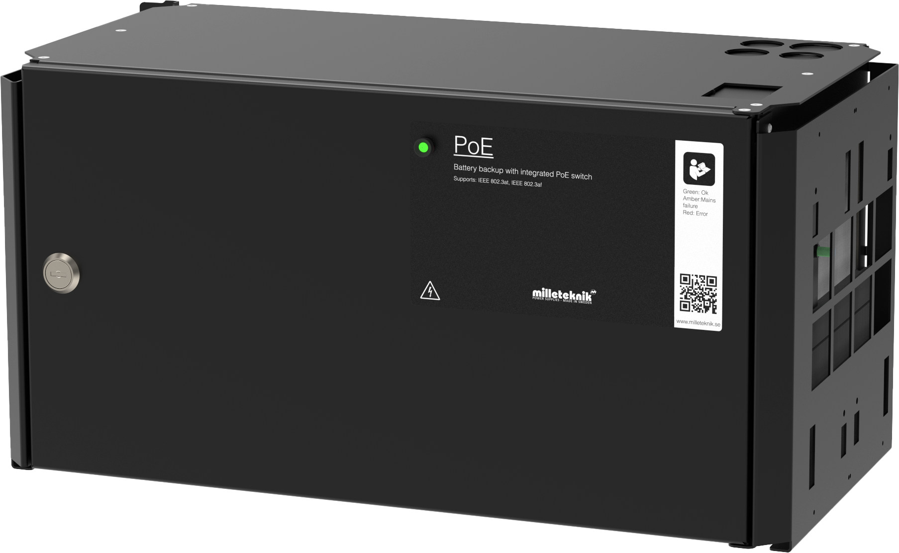
About PoE from Milleteknik
The series is designed to power PoE devices such as access systems, surveillance cameras and other equipment that can be operated with Power over Ethernet.
PoE M-switch 4p FLX M, PoE M-switch 8p FLX M and PoE M-Switch 16p FLX M meet 802.3at type2 class 4. The PoE switch is managed, i.e. it is possible to control the switch via its software interface. The products have something we call "controlled charging", which is a safety function that means that batteries are not charged with more than 4.5 A. By controlling the charging of batteries, the lifespan of batteries is significantly extended. The product has 24 V battery voltage which is boosted up to 48 V to power the PoE switch. There is a load output on the motherboard that provides 24V, this allows the device to be used to power other applications such as door locks, etc on the one load output. It is important to accurately calculate the load so that the unit's specifications are not exceeded. Battery box can be connected for extended backup drive time.
How PoE powers devices connected to the power supply
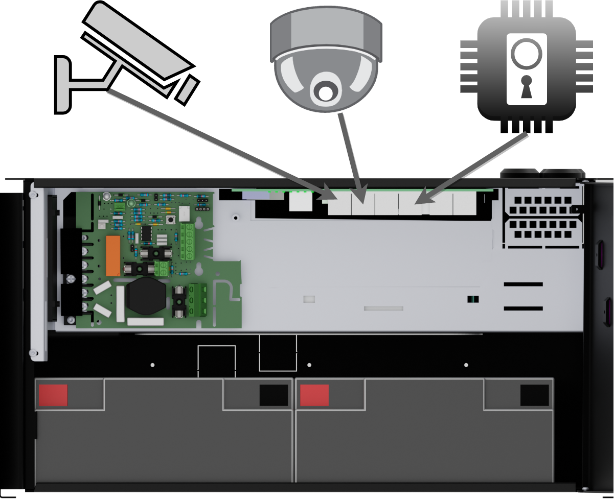 |
PoE can power, for example, surveillance cameras.
Connect external devices to be powered via PoE in PoE ports.
Connect other devices that do not need to be power supplied in LAN ports.
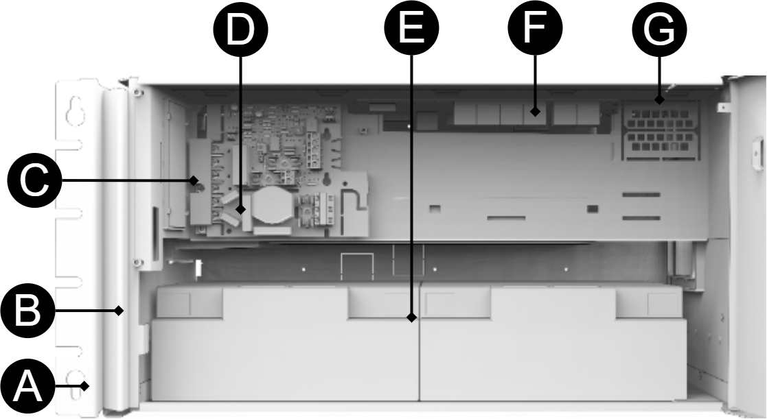
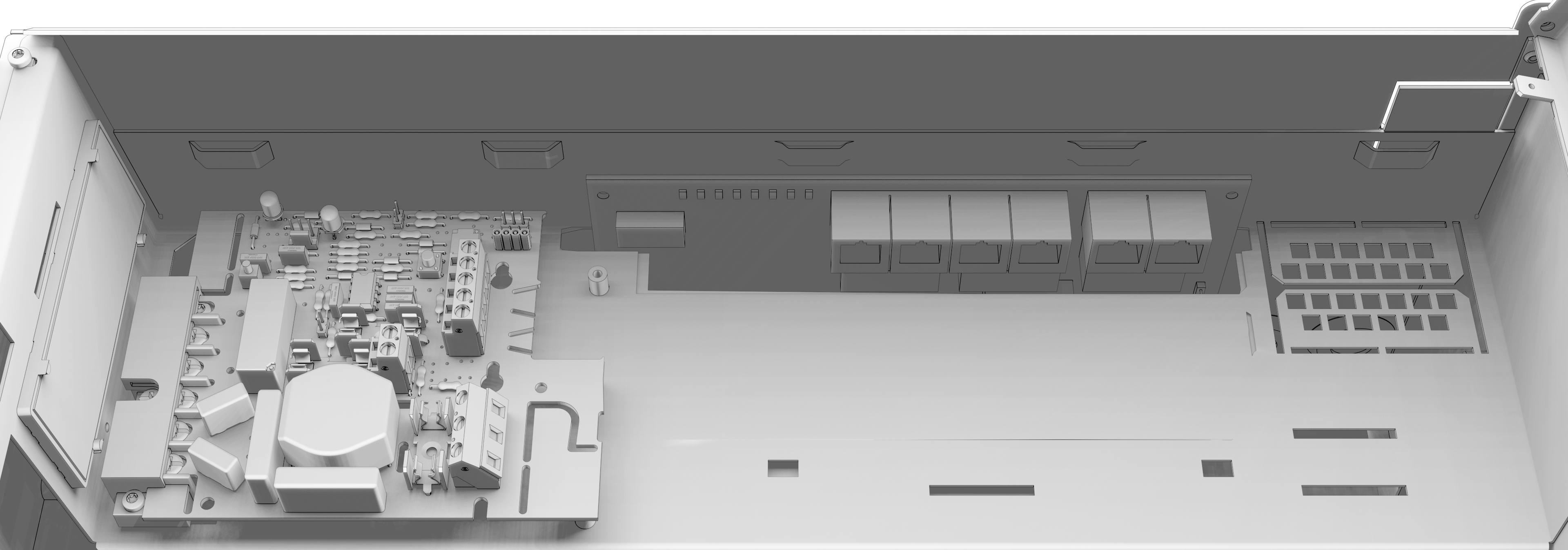
Component overview PoE FLX M
Symbol | Explanation |
|---|---|
A | Brackets, reversible. |
B | Casing in powder-coated sheet metal. |
C | Power supply, (placed under the motherboard). |
D | Motherboard. |
E | Room for batteries. |
F | Eight PoE ports are clustered together and two LAN ports are clustered together. |
G | Cable entries. |
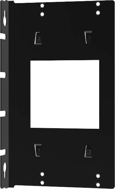
Console for FLX M and FLX L
Bracket is reversible and can be mounted in two ways. It comes with brackets in to the device.
 |
Batteries - placement and connection
Connection of batteries in FLX S, FLX M and FLX L
Battery wiring is mounted on the circuit board upon delivery. Pictures below only show how to connect wiring.
Place the batteries in the cabinet with the battery terminals facing outwards.
Connect the battery cable. Red cable on + and black cable on -.
If possible, disconnect mains voltage when replacing the battery.
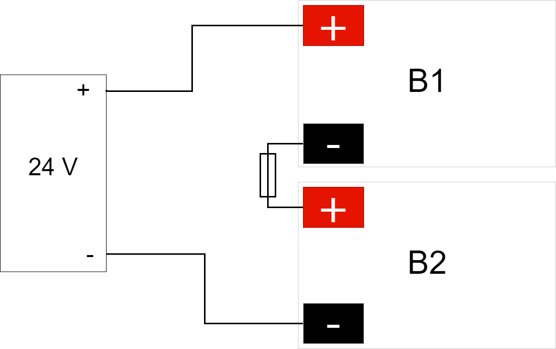
Connect the terminals correctly so that you do not damage the equipment.
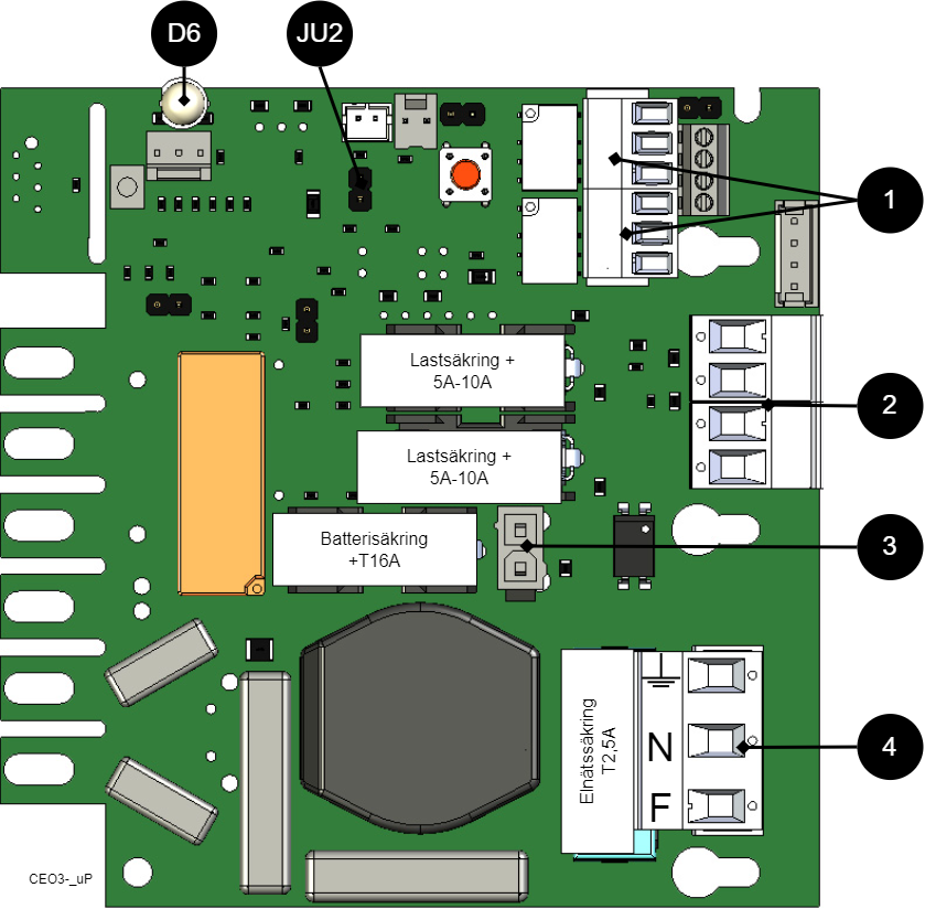
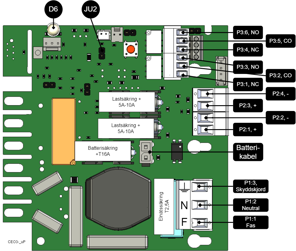
Motherboard description
Connect in this order
To minimize the risk of errors that may occur in connection with a short circuit, connections to the motherboard must be made in this order.
Nr | Explanation |
|---|---|
1 | Connect alarm. |
2 | Connect load. |
3 | Connect batteries |
4 | Connect mains. |
On PCB | Explanation |
|---|---|
D6 | Indicator diode. |
JU2 | Jumper for alarm control. When the jumper is mounted, the alarm limit is lowered. |
P1:1-3 | Mains connection. |
P2:1-2 | Load output, + / -. |
P2:3-4 | Load output, + / -. |
P3:1-3 | Alarm output, NC, CO, NO. |
P3:4-6 | Alarm output, NC, CO, NO. |
Connect alarm on P3
Alarm is connected to terminal P3
P3:1-6 | Explanation |
|---|---|
Sum alarm | |
P3:1 | NC |
P3:2 | Com |
P3:3 | NO |
Sum-alarm* | |
P3:4 | NC |
P3:5 | Com |
P3:6 | NO |
Total alarm: Broken fuse on load, broken fuse from external distribution board, broken battery fuse, low battery voltage in battery operation, batteries not connected, overvoltage.
Connect load
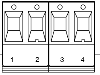
Circuit board number | Explanation |
|---|---|
P2: 1 | Connection for load 1 + |
P2: 2 | Connection for load 1 - |
P2: 3 | Connection for load 2 +. |
P2: 4 | Connection for load 2 -. |
Max current
The maximum current must not be exceeded. Max current is indicated on nameplate on the device.
Danger
Mains voltage must be disconnected when working with stripped cables. It is the installer's responsibility to ensure that the correct skills are available for connecting 230 V to the unit. Maximum cable area is 4 mm2
Connect mains
Pull wiring through the cable entry on the cabinet.
If possible, secure the mains cable with cable ties where possible.
Electrical network cabling shall be kept separate from other cabling to avoid EMC interference.
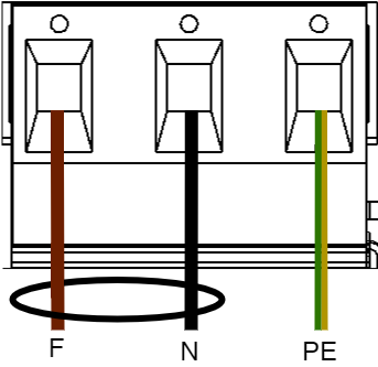
Connect the mains cable to the terminal before it is put back on the motherboard. Secure F and N with cable ties for electrical safety.
Letter | Explanation |
|---|---|
F | Phase |
N | Neutral |
PE | Protective earth |
Electrical mains connection 230 V AC on circuit board
Check that the marking on the circuit board matches the cable arrangement on the terminal block.
Control alarm limit
Alarm for low battery voltage in battery operation can be controlled.
By jumpering JU2, the limit for when the unit should give an alarm can be lowered.
Alarms are given when the battery voltage in battery drops below the limit.
Fuses
Unit | Fuse | Type | Explanation |
|---|---|---|---|
All units | F1 | T2,5A | Mains fuse |
| F2, F6 | T10A | Load fuse + |
All units | F7 | T16A | Battery fuse |
Fuse Replacement Warning (A)
There is a risk of damage if the fuse is changed to a larger one than what the unit is delivered with. The function of the fuse is to protect the connected load and cables against damage and fire. It is not possible to change the fuse to a larger one to increase the power output.
The differences between PoE switches
Product | PoE switch installed | Can additional PoE switches be installed? |
|---|---|---|
PoE M-switch 4p FLX M | A four 4 port PoE Switch | No . |
Short description for PoE switch 4p
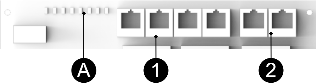
No | Explanation |
|---|---|
1 | 4 pcs RJ-45 powered ports for connecting PoE devices. |
2 | 2 pcs RJ-45 ports for data, not PoE, (powered). |
A | Indication, green LED lights up when device is plugged in. This is only an indication that the port is connected and not the connected device's status. |
Commissioning - how to start the unit
Connect batteries.
Connect fuses.
Plug in PoE and other loads.
Screw the mains cable into the terminal and attach the terminal to the motherboard.
Switch on mains voltage.
The unit works normally when the indicator LED on the outside of the cabinet door lights up with a solid green light. See front panel for other status indications.
It may take up to 72 hours before the batteries are fully charged.
How the PoE switch software is accessed
How the software is accessed in the PoE Switch
This section shows how to log in to the switch's configuration web page.
In order to configure the software in the switch, access to the switch requires the correct IP address to be set on the computer.
Access to the switch's software is through a browser (Chrome, Edge, Firefox).
Follow the steps to access the switch's settings.
Note
The settings shown are settings for PC, (Windows 7 - Windows 11). Windows and names may vary between different versions of Windows. Unfortunately, we cannot provide support for settings of your computer.
Notice
The address of the PoE switch is: 192.168.2.1 and username and password are: admin/admin The IP address in the switch is static (fixed) and therefore the computer's IP address and subnet mask must be static.
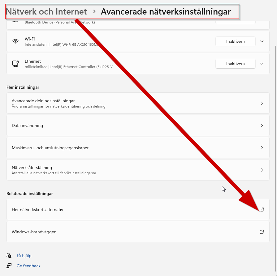
Open settings and go to Network and Internet -> Advanced network settings. Open more network card options.
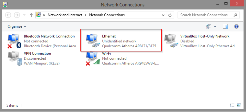
A Network Connections window will appear showing all available network connections on the computer. Double-click the network connection you use to connect to the switch.
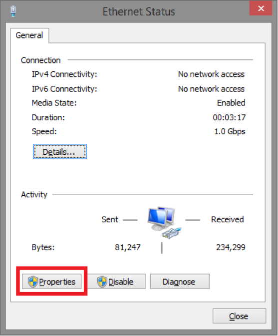
Ethernet status window appears. click the button Characteristics as shown in the figure below.
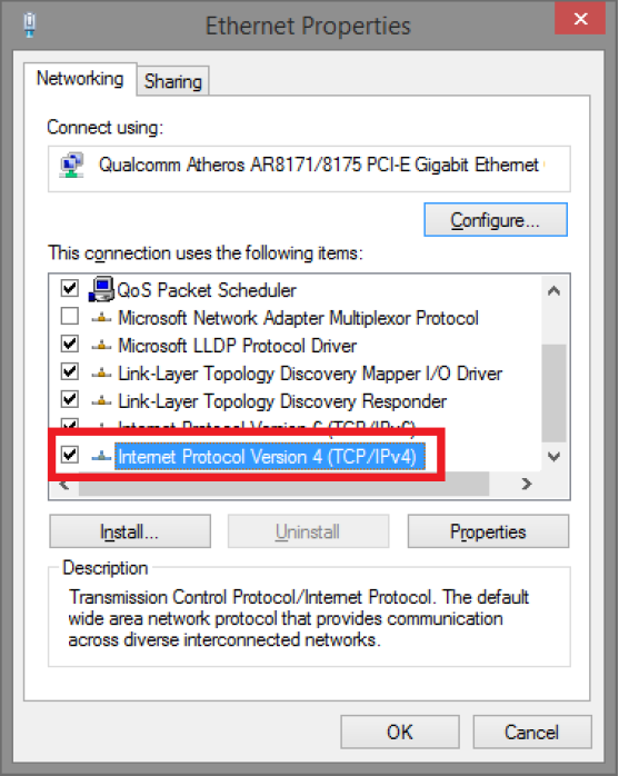
Double-click Internet Protocol Version 4 (TCP / IPv4).
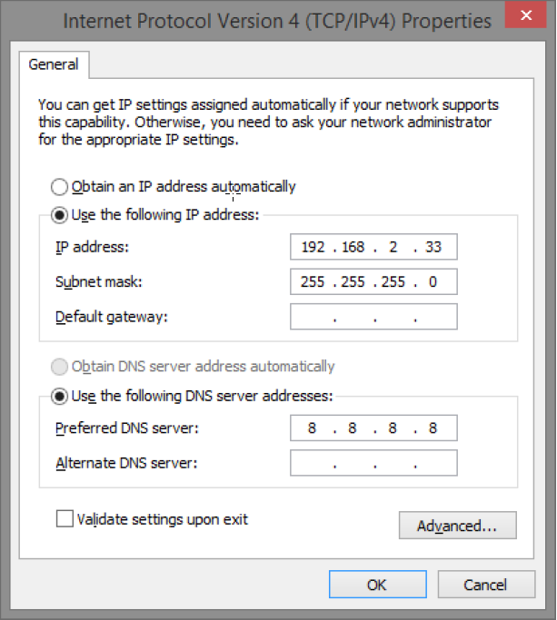
Set the computer's IP address and subnet mask as shown in the figure below. By default, the product's IP address be 192.168.2.1. You can set any IP address as long as it is not the same as your switch's IP address and is in the same network segment as your switch's IP address. Press OK to apply the TCP/IPv4 settings you just made. Now you can connect to your switch using a web browser (Chrome, Edge or Firefox).
Connect an RJ-45 cable and connect to the PoE switch.
Log in to the PoE switch
Note
IP address of the switch (factory setting): 192.168.2.1
Password (factory setting): admin
Start the browser on your computer.
Login to PoE switch.
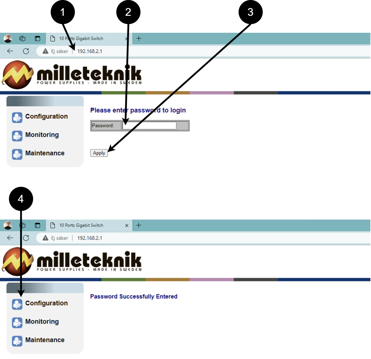
Number
Explanation
1
IP address of the PoE switch: 192.168.2.1
2
Password: admin
3
Apply = Ok
4
Menu in the PoE switch
Configuration
System, configuration
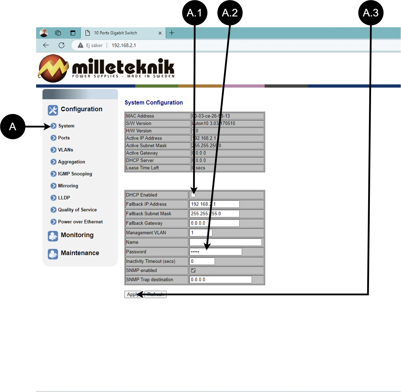
Letter, number | Explanation |
|---|---|
A | PoE switch system configuration page |
A.1 | Tick here if you are going to use DHCP, see warning below. |
A.2 | Changes the factory default password, (admin). |
A.3 | If you have made any changes, you need to click "Apply" to save the changes. |
Ports, configuration
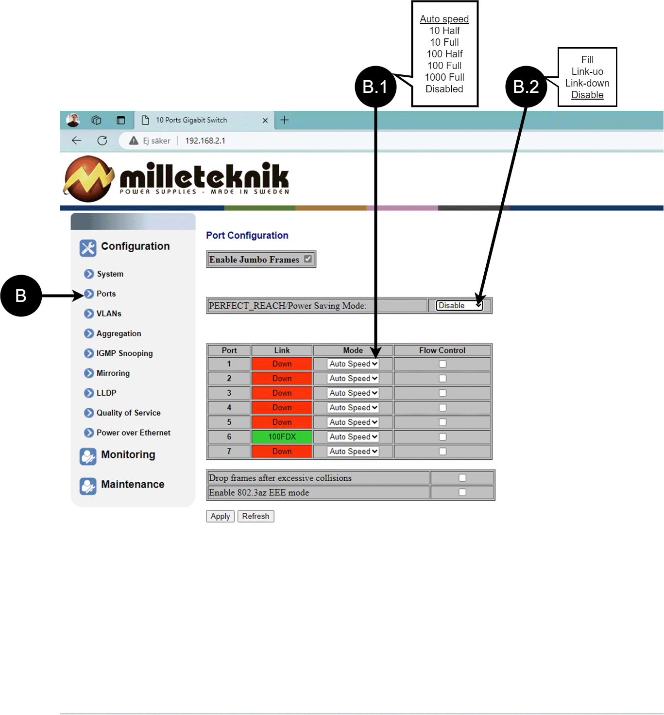
Letter, number | Explanation |
|---|---|
B | Gates |
B.1 | This setting normally does not need to be changed. Select the speed of the PoE switch's ports. |
B.2 | This setting normally does not need to be changed. |
VLAN configuration
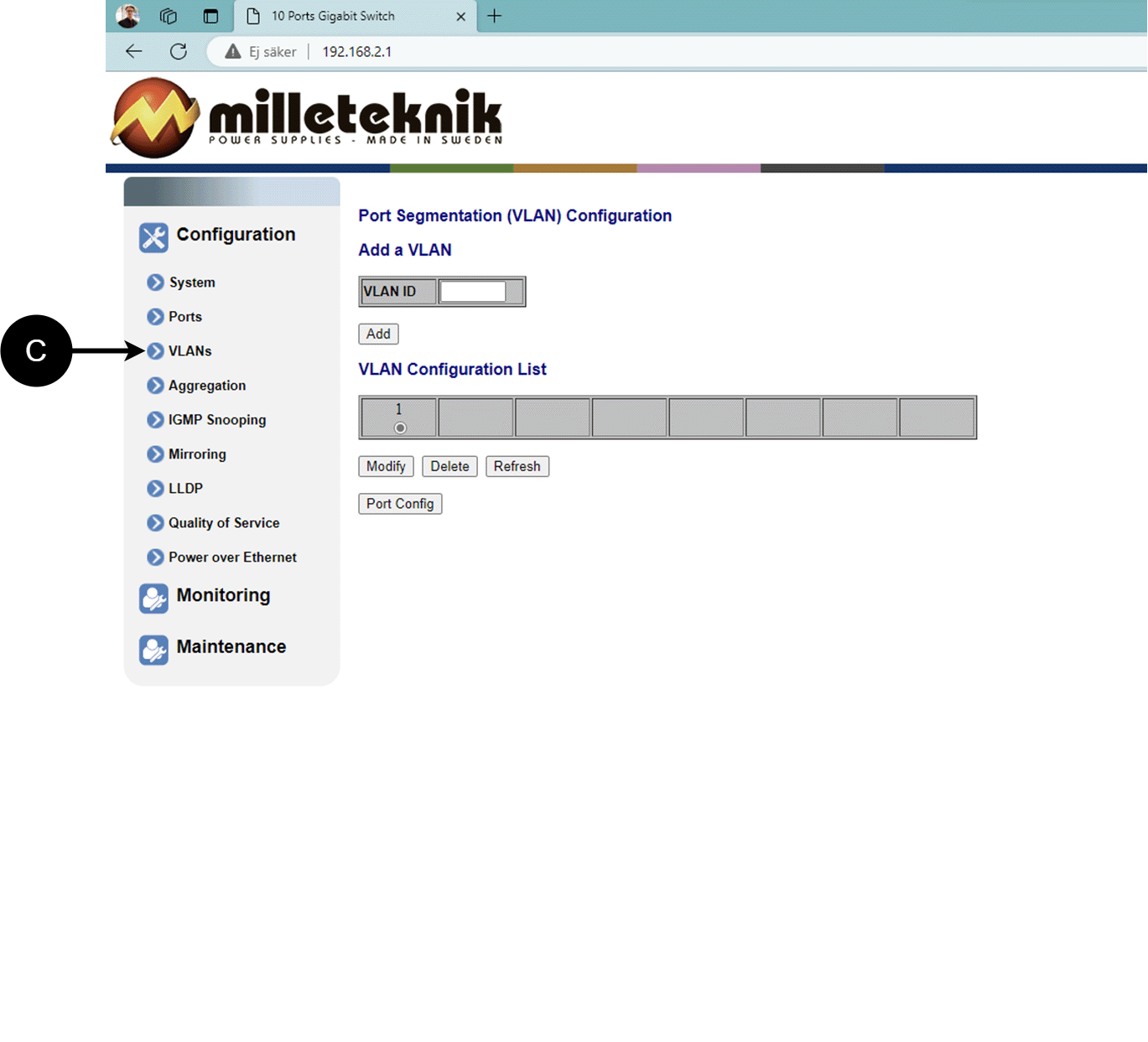
Configuration of Virtual LAN.
Aggregation, configuration
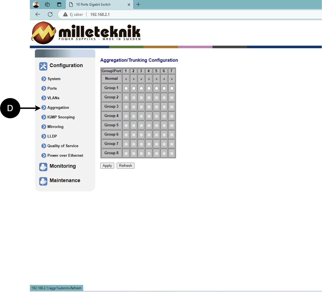
Load balancing between the ports.
IGMP Snooping, configuration
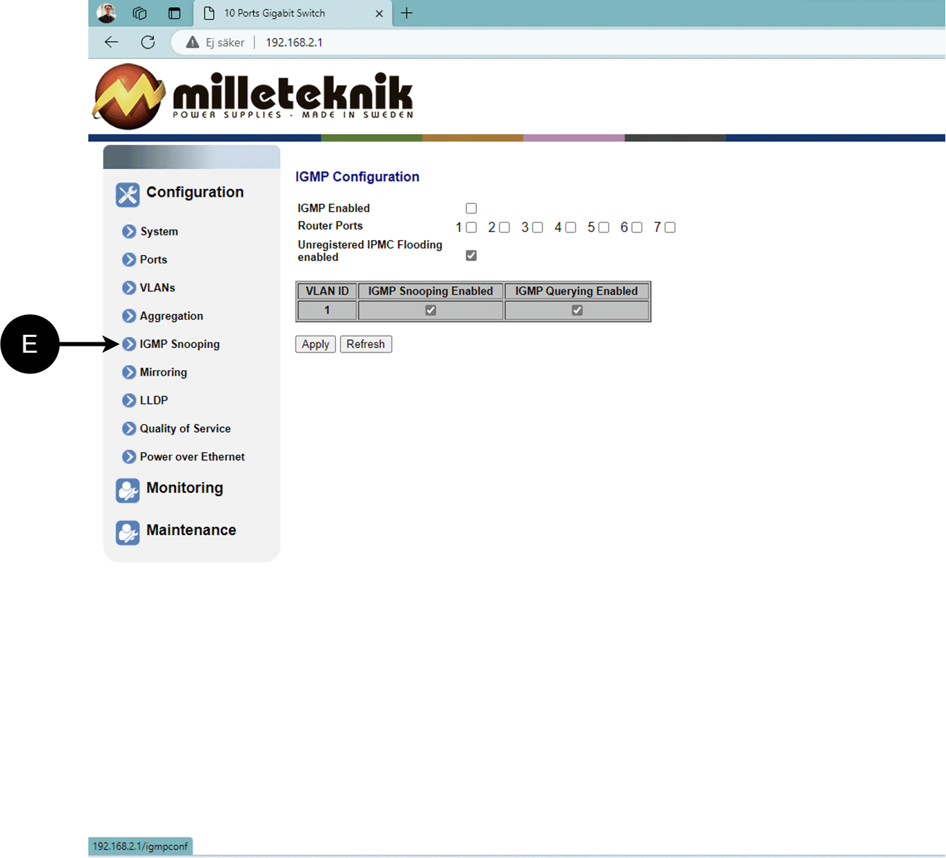
Switch that controls reception.
Mirroring, configuration
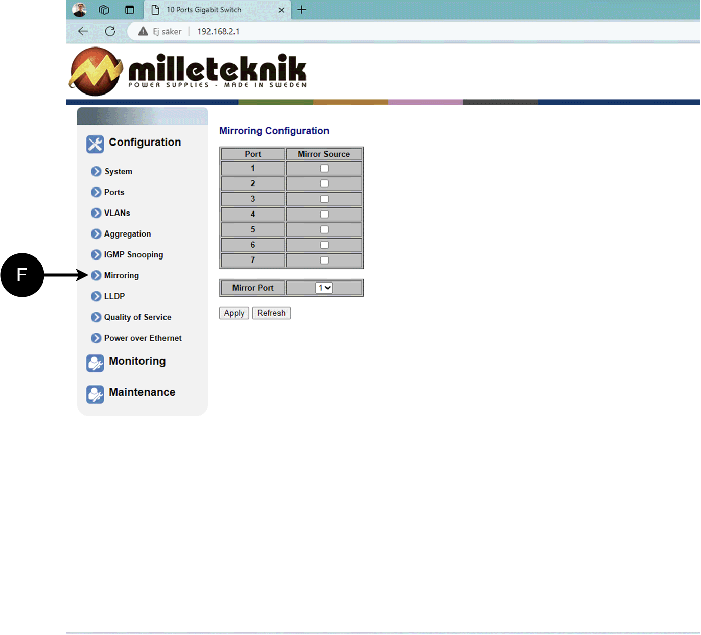
Mirroring of ports.
LLDP configuration
Letter, number | Explanation |
|---|---|
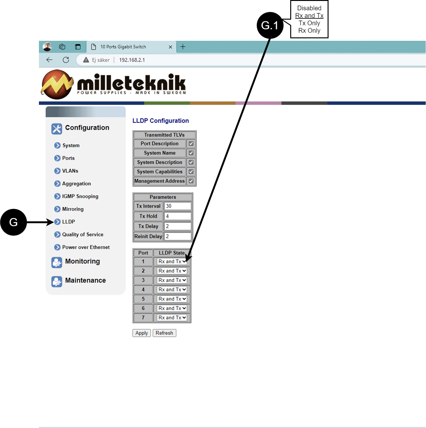
G | LLDP stands for "Link Layer Discovery Protocol", which is a network protocol standard used to discover and communicate information about network devices connected to the same Ethernet network. The protocol allows devices such as switches and routers to send and receive messages containing information about the device's identification, capabilities, and connection topology. |
G.1 | RX and TX are abbreviations used in electronics, communications, and computer networking to indicate the direction of data flow between devices. RX: The abbreviation "RX" stands for "Receive" or "Reception". It indicates that the device is receiving data or signals from another device. When a device has an RX input, it means that it is designed to receive data or information from a transmitting device. TX: The abbreviation "TX" stands for "Transmit" or "Transmission". It indicates that the device is transmitting data or signals to another device. If a device has a TX output, it means that it is designed to transmit data or information to a receiving device. These abbreviations are especially common when it comes to data communication, such as in the context of network cables where there are specific RX and TX wires that allow for two-way communication between devices. |
QoS, configuration
Letter, number | Explanation |
|---|---|
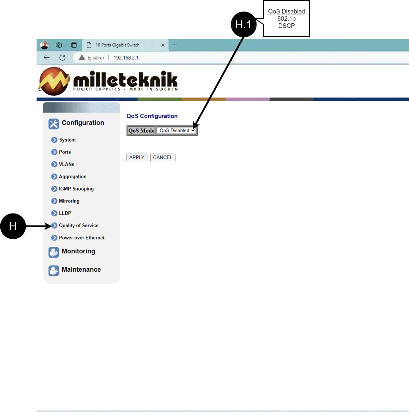
H | QoS gives different network traffic different priority depending on its importance and requirements, helping to ensure that important services are delivered with sufficient bandwidth and minimal delay even when the network is under load. |
H.1 | Sets whether QoS is active. |
PoE, configuration
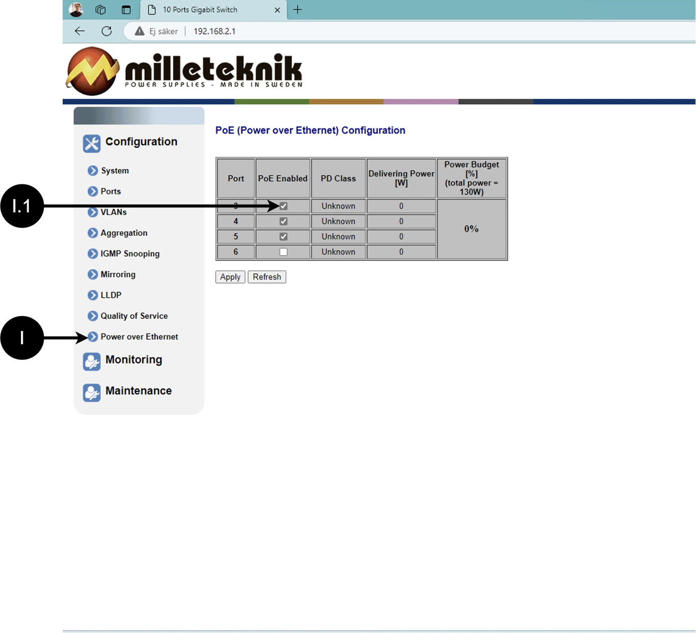
Letter, number | Explanation |
|---|---|
I | Power over Ehternet |
I.1 | Turns PoE port on or off. Don't forget to press "Apply" to save changes. |
Monitoring
Statistics, overview
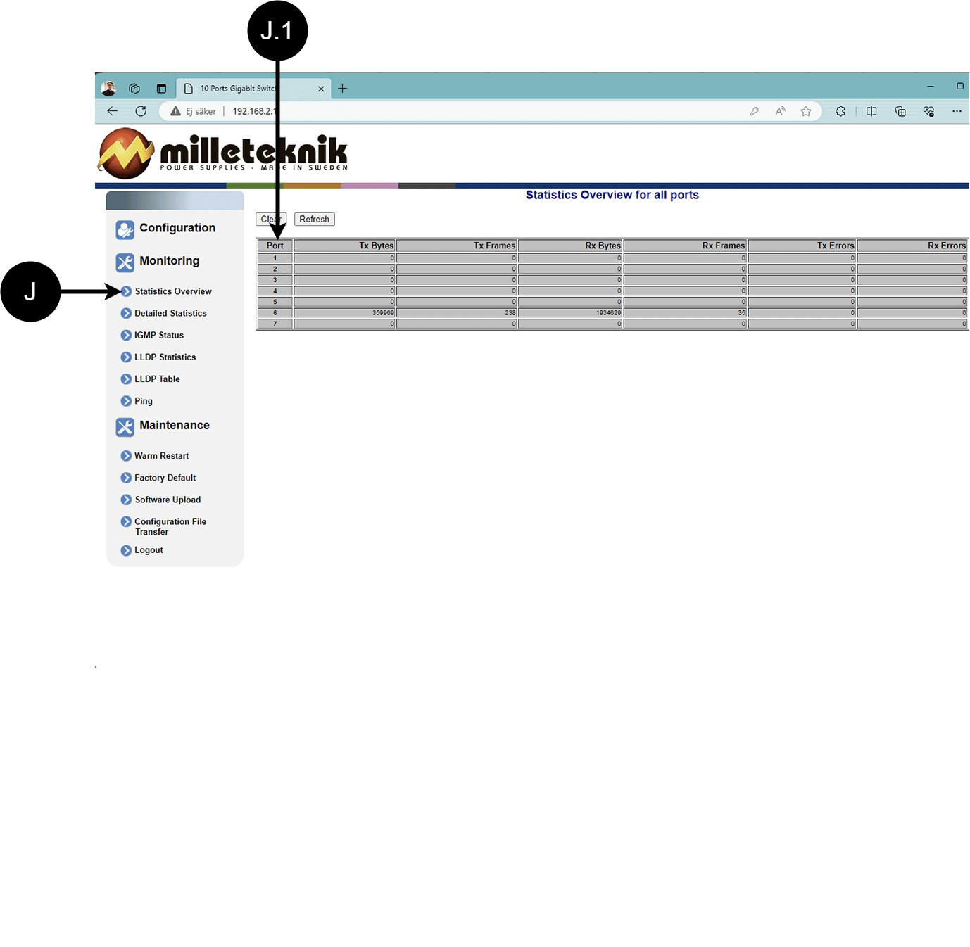
Letter, number | Explanation |
|---|---|
J | Statistics, overview |
J.1 | Traffic per port. |
Statistics, detailed
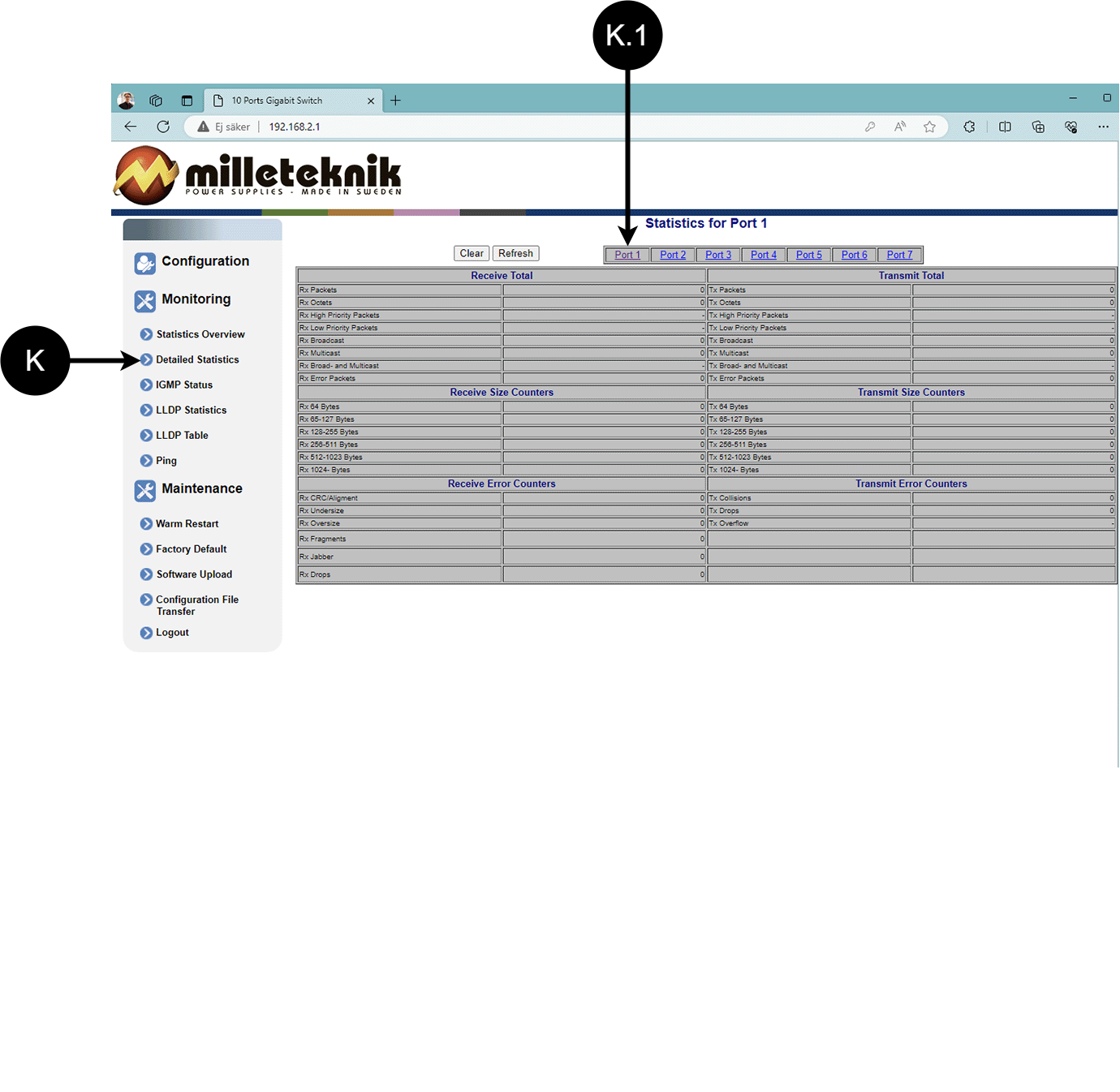
Letter, number | Explanation |
|---|---|
K | Detailed statistics |
K.1 | Select the port for which you want statistics. |
IGMP status
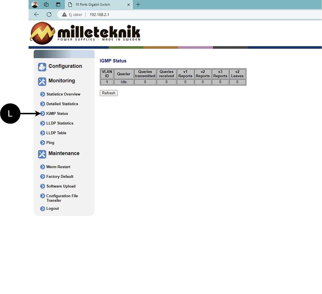
L: Status of IGMP
LLDP statistics
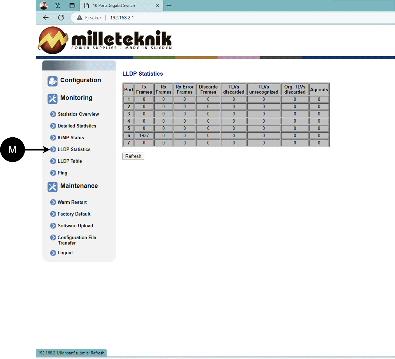
M: LLDP statistics
LLDP table
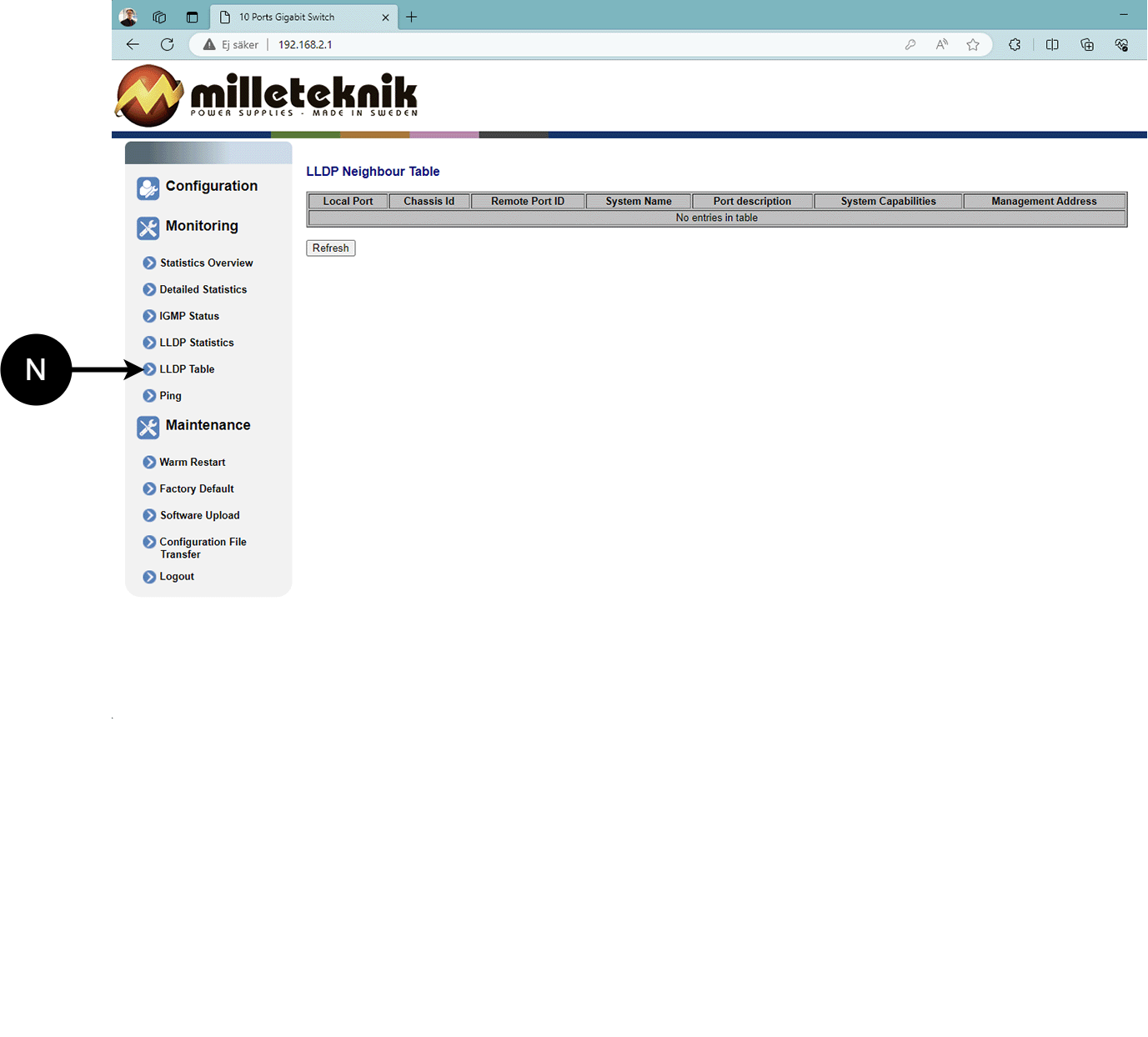
N: LLDP overview.
Ping
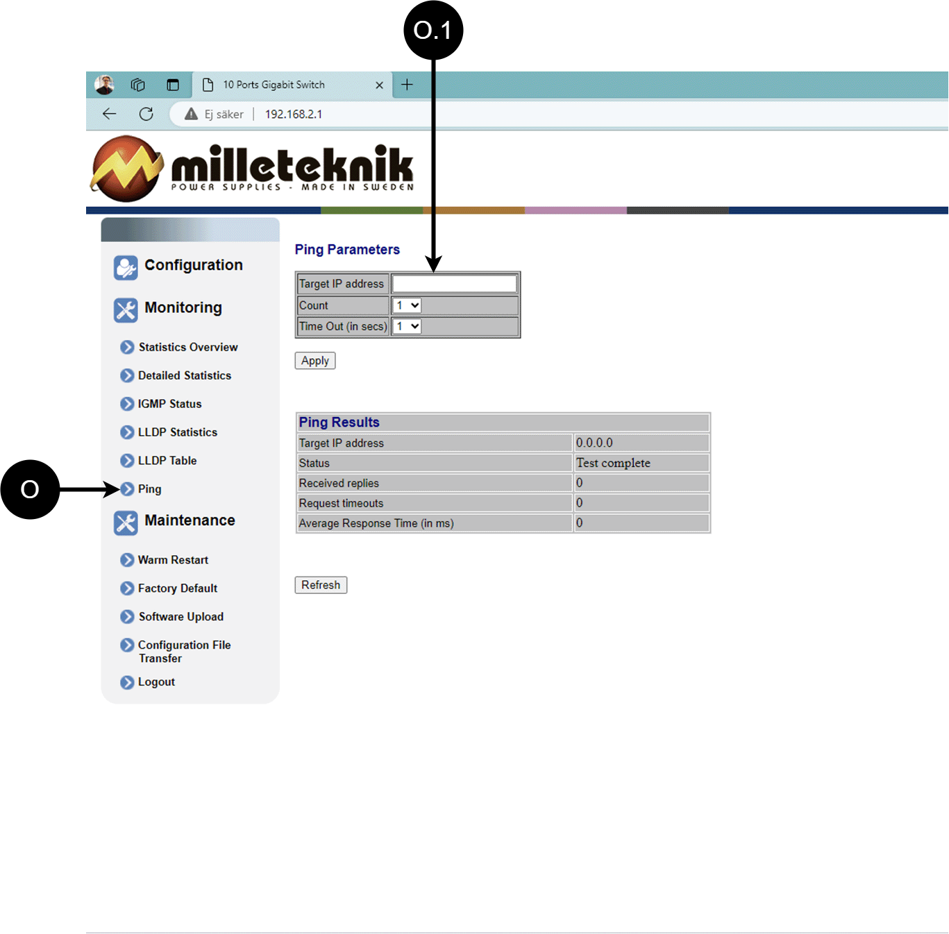
Letter, number | Explanation |
|---|---|
O | Ping |
0.1 | Input address to test the connection and response time. |
Maintenance
Reboot
Warning
Restart is done by PoE switch, battery backup is not restarted. Upon reboot, connected devices will lose connection. Alarm can be set to battery backup, but it disappears when the PoE switch is back on.
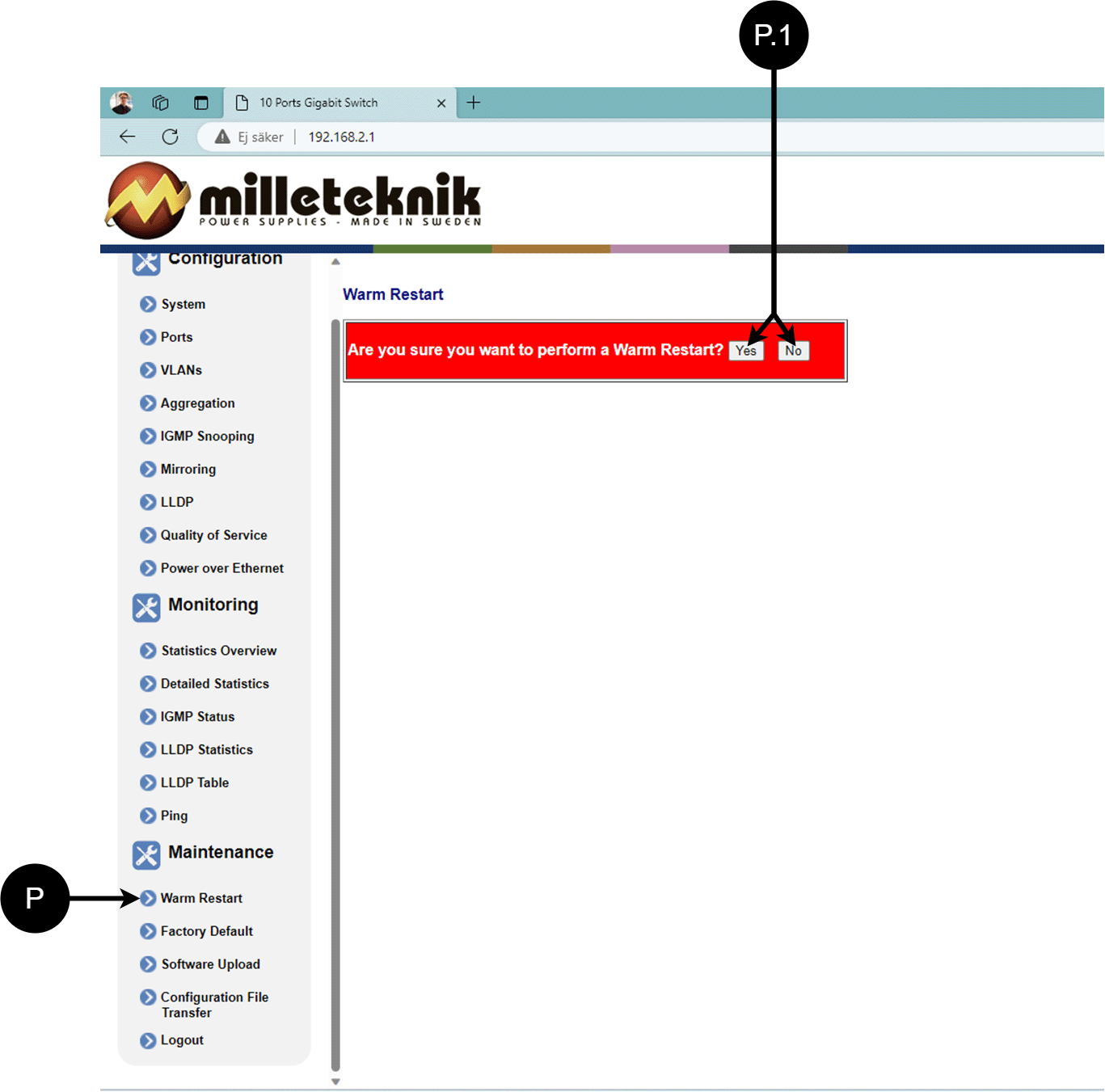
Letter, number | Explanation |
|---|---|
P | Rebooting the PoE switch. |
P.1 | Select "Yes" to reboot the switch. |
Factory reset
Warning
Factory reset is done by PoE switch. Battery backup is not restored. On reset, connected devices will lose connection. Alarm can be set to battery backup, but it disappears when the PoE switch is back on.

Letter, number | Explanation |
|---|---|
Q | Factory reset the PoE switch. |
Q.1 | Select "Yes" to factory reset the PoE switch. |
Upload new software
Warning
Only use software you received from Milleteknik's support. Milleteknik assumes no responsibility for software or consequences such as damage to the device or peripherals or other damage that may arise from uploading unapproved software.
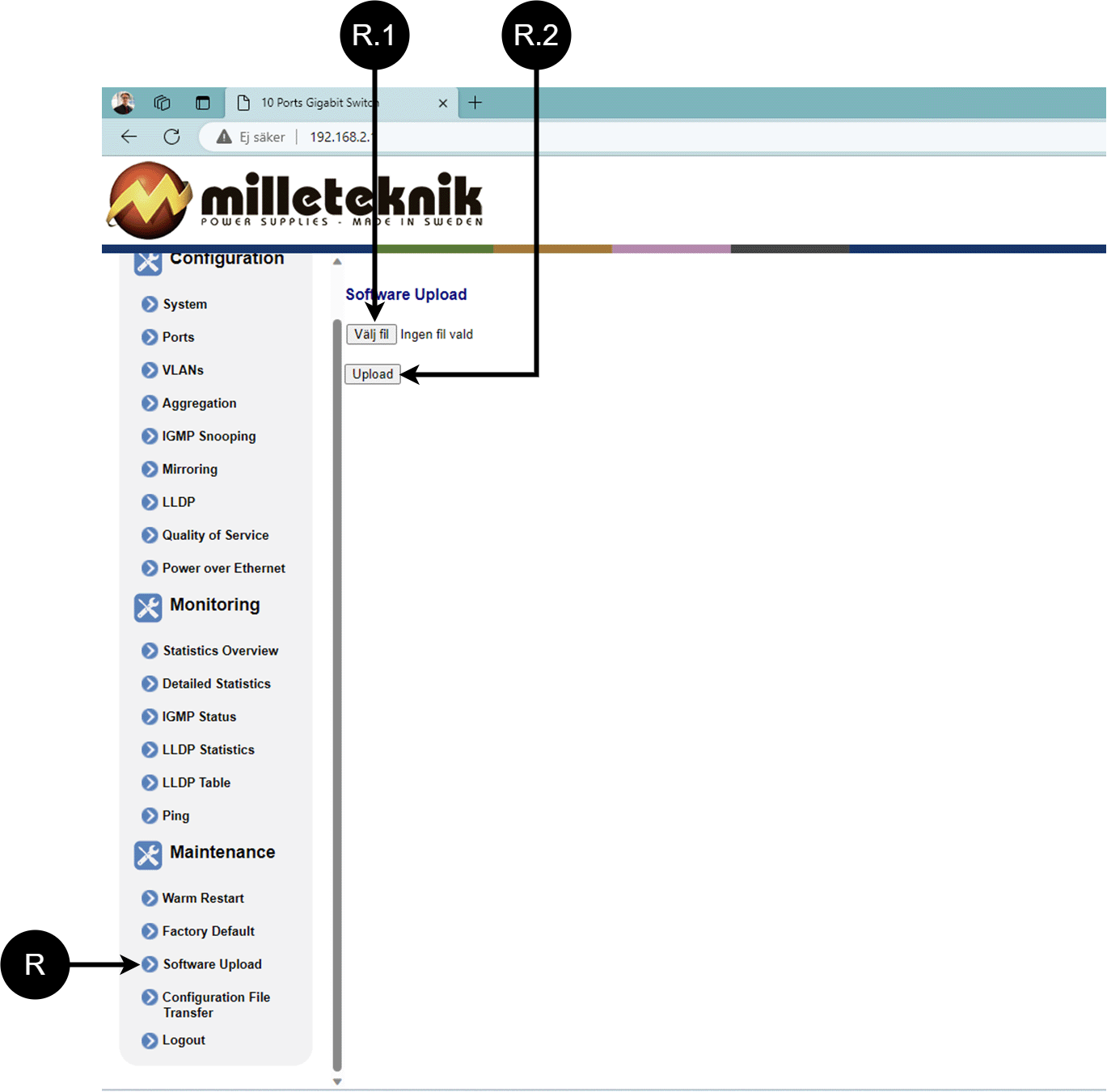
Letter, number | Explanation |
|---|---|
R | Upload new software to the Switch. |
R.1 | Navigate to the computer where you saved the file. |
R.2 | Click "Upload" to upload the software. |
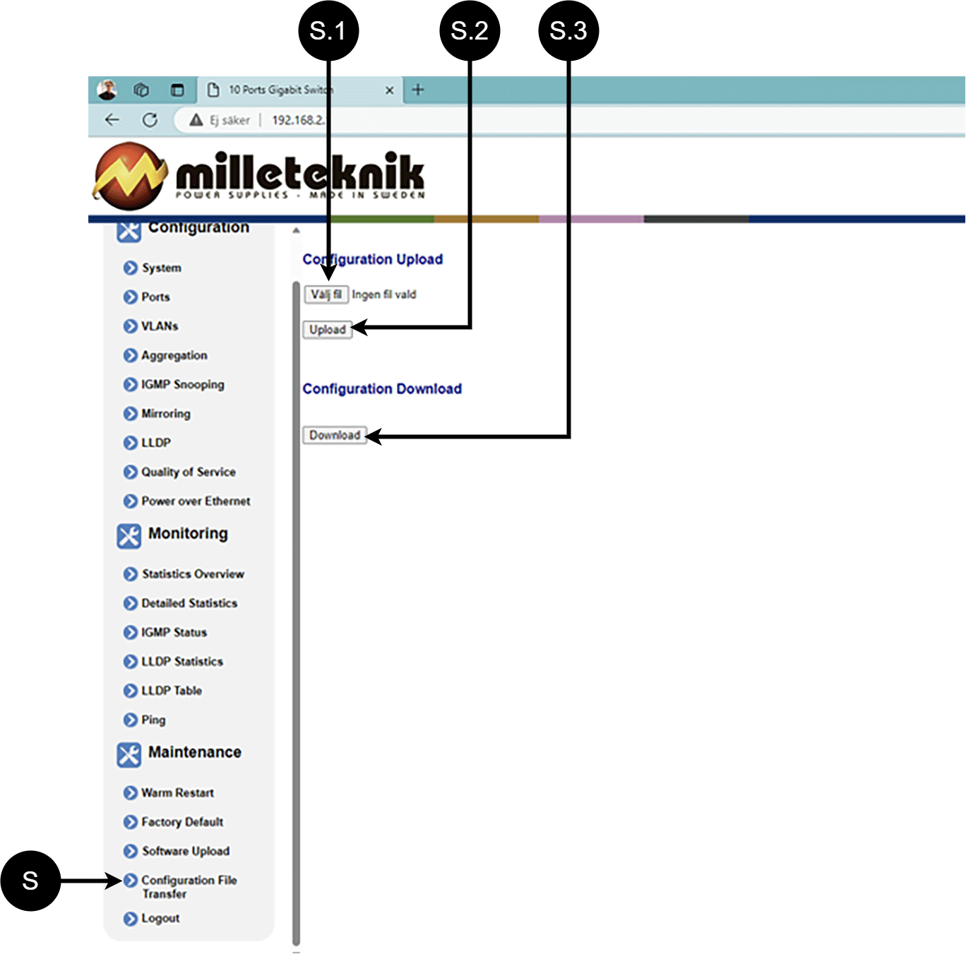
Load and save configuration file
Letter, number | Explanation | ||||||||||||||||||||||||||||||||||||||||||||||||
|---|---|---|---|---|---|---|---|---|---|---|---|---|---|---|---|---|---|---|---|---|---|---|---|---|---|---|---|---|---|---|---|---|---|---|---|---|---|---|---|---|---|---|---|---|---|---|---|---|---|
S | Upload or download the switch's configuration. | ||||||||||||||||||||||||||||||||||||||||||||||||
S.1 | Select new configuration file. | ||||||||||||||||||||||||||||||||||||||||||||||||
S.2 | Upload new configuration file. | ||||||||||||||||||||||||||||||||||||||||||||||||
S.3 | Download configuration file to computer[a]. | ||||||||||||||||||||||||||||||||||||||||||||||||
[a] Newer Windows computers do not allow *.cfg files to be downloaded without additional approval in the browser when downloading. Antivirus programs may delete the file during download. | |||||||||||||||||||||||||||||||||||||||||||||||||
Log out
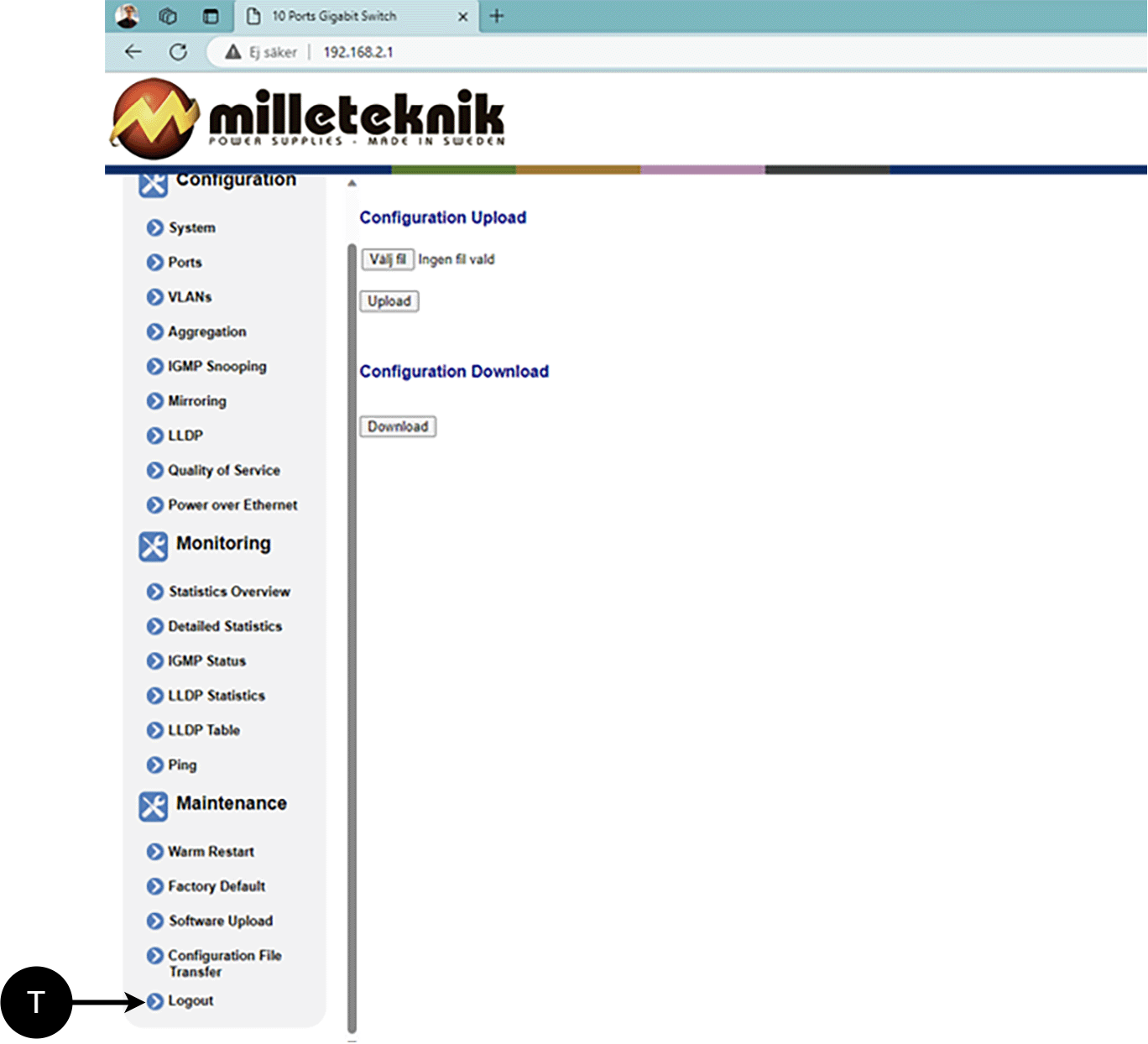
T: Log out of the switch. This does not affect the operation of the switch.
Alarm displayed on cabinet door
In normal mode, the indicator LED shows a solid green light.
 |
The indicator diode shows | Explanation |
|---|---|
Solid green light | Normal operation. |
Solid yellow glow | Mains failure. |
Solid red light | Battery not connected / blown fuse. |
When operating system: If the indicator LED is off, deep discharge protection has come into force.
Maintenance
The system with the exception of batteries is maintenance-free when installed in an indoor environment.
battery change
If possible, disconnect mains (voltage) when replacing the battery.
Disconnect battery cables. Note how battery cables are mounted before removing them.
Remove battery fuse between batteries.
Insert and fasten the new batteries.
Connect the battery cables in the same way as before.
Connect battery fuse between batteries.
Switch on mains voltage. The indicator LED may not be green (up to 72 hours), until the batteries are charged.
Test the system by briefly disconnecting the mains voltage, (= the load is driven by the batteries), and then switch on the mains voltage again.
Product sheet - power supply / battery backup
Product sheet - power supply from Milleteknik
PoE
Managed PoE switch with 4 PoE Ports.
Name, article number and e-number
Name | Article number | E-number (SV) |
|---|---|---|
PoE M-Switch 4p FLM | FM01N10224P01004PM | 51 728 96 |
Description
Primary switched four, eight or 16 PoE-ports, power supply with battery backup 24 V, 30.8 W/port, with room for two 20 Ah batteries.
Area of use
Power supply with backup power to power PoE devices such as surveillance cameras and other PoE powered devices. A plate for keystone modules makes the installation of PoE devices easier. An additional load output to power other 24 V applications.
Batteries drive, for example, the access system, when the power grid goes down.
Long life, energy efficient and support is available if something goes wrong, now or in 10 years.
Technical description
Plate for attachment of Keystone modules.
1 GB ports.
Constant output voltage, 24 V , regardless of battery or mains operation, which means that the entire battery capacity can be used.
For mounting on a wall or in a 19" rack.
Voltage, current and power
Mains voltage: 230 V AC - 240 V AC, 47 Hz - 63 Hz.
Load outputs
PoE switch can drive load to PoE devices and motherboard can drive one (1) 24V load output to drive other applications.
Alarm
Alarms are given for: Delayed power failure alarm or low battery voltage, disconnected batteries, fuse failure and overcharging of batteries.
Protection
Protection against overload, overvoltage, overtemperature, short circuit and deep discharge.
Controlled charging of batteries protects against overcharging and extends the life of batteries. Batteries are charged with a maximum of 4.5 A.
Fuses
Mains fuse: 2.5 A.
Load securing: Fuse on supply to PoE switch : 10A. Fuse on load output: 10 A.
Battery fuse: 30 A.
Indications and communication
LED displays information and alarms on the circuit board and on the enclosure door.
PoE power supply can not communicate via protocol (RS-485/I2C) against UC.
Battery and battery type
Two 7 Ah, Two 14 Ah, or two 20 Ah batteries.
Battery type: 12 V, AGM lead-acid battery, maintenance-free. Batteries not included.
Backup operating time on batteries
The reserve operating time in battery operation depends on how large a load is connected to the power supply. If the load varies, as with frequent opening of door locks, the time that batteries can continue to power the security system decreases. To get an estimate of reserve operating times see: www.milleteknik.se/Manualer/FaQ/Reservdrifttider/
Enclosure
Weight
Name | Net weight | Weight incl. packaging |
|---|---|---|
PoE M-switch 4p FLX M | 7.8 kg | 8.55 kg |
Installation requirements
The device is intended for fixed installation. The unit must be installed indoors, environmental class 1, ambient temperature: +5°C to +40°C. Recommended ambient temperature is +15°C to +25°C (for optimal battery life).
Requirements that the product meets
EMC: | EMC Directive 2014 / 30EU |
Electricity: | Low voltage directive: 2014/35 / EU |
PoE: | IEEE 802.3af, IEEE 802.3at/30.8 W Note that 802.3at type2 is not supported, as the PoE card lacks a handshake function for type 2. IEEE 802.3af, IEEE 802.3at/30.8 W up to Type2, Class 4. |
CE: | CE directive according to: 765/2008 |


Guarantee
Expandable, options and accessories
Manufacturing, lifespan, environmental impact and recycling
Manufactured by Milleteknik in Partille, Sweden.
Link to the latest information
Products and software are subject to updates, you will always find the latest information on our website.
Link to technical specifications
Miscellaneous
The difference between PoE, PoE+ and PoE++.
About this information
All information is published subject to possible errors. This document is updated without notice. |
Product life cycle, environmental impact and recycling
The product is designed and constructed for a long service life, which reduces the environmental impact. The product's service life depends on, among other things, environmental factors, mainly ambient temperature, unforeseen load on components such as lightning strikes, external damage, handling errors, and more. Products are recycled by being handed over to the nearest recycling station or sent back to the manufacturer. Contact your distributor for more information. Costs that arise in connection with recycling are not reimbursed.

Address and contact details
Milleteknik AB |
Ögärdesvägen 8 B |
S-433 30 Partille |
Sweden |
+46 31 340 02 30 |
info@milleteknik.se |
www.milleteknik.com |