Revisions and the edition of this document
The current and most recently published edition of this document is available at www.milleteknik.com.
The validity of this document can not be guaranteed, as new editions are published without prior notice.
User manual in original language: Swedish.
Instructions for use, technical data and translations thereof may contain errors. It is always the responsibility of the installer to install the product in a safe manner.
Read this first!
Electronics, regardless of enclosure, are intended for use in a controlled indoor environment. Mains voltage should be disconnected during installation.
It is the installer's responsibility that the system is suitable for its intended use. Only authorized persons should install and maintain the system.
All information subject to change.
Instruction manual in Swedish in original[1].
About glass tube fuses on certified devices
There are glass tube fuses on the circuit board's load outputs, these have a tripping time of approx. 150 ms. In the event that a glass tube fuse trips on ONE load output, the voltage on ALL load outputs drops to 0 V for 150 ms.
The installer is responsible for ensuring that there is an energy buffer of at least 150 ms in systems that the battery backup supplies power to or accepts a power failure of 150 ms.
Variant overview NOVA
Product name | Certified name | Motherboard: PRO1 | Motherboard PRO2: | Motherboard PRO2 v3 | Motherboard: PRO3 |
|---|---|---|---|---|---|
NOVA 12V 10A FLX S | 12 V meets the requirements but is not certified. | - | - | - | x |
NOVA 12V 10A FLX M | - | - | - | x | |
NOVA 12V 10A FLX L | - | - | - | x | |
NOVA 24V 5A FLX S | NOVA 25 50-FLX-S | X | X | - | X |
NOVA 24V 10A FLX S | NOVA 25 100-FLX-S | X | X | - | X |
NOVA 24V 5A FLX M | NOVA 25 50-FLX-M | X | X | - | X |
NOVA 24V 10A FLX M | NOVA 25 100-FLX-M | X | X | - | X |
NOVA 24V 15A FLX M | NOVA 25 150-FLX-M | X | X | X | - |
NOVA 24V 25A FLX M | NOVA 25 250-FLX-M | X | X | X | - |
NOVA 24V 5A FLX L | NOVA 25 50-FLX-L | X | X | - | X |
NOVA 24V 10A FLX L | NOVA 25 100-FLX-L | X | X | - | X |
NOVA 24V 15A FLX L | NOVA 25 150-FLX-L | X | X | X | - |
NOVA 24V 25A FLX L | NOVA 27 250-FLX-L | X | X | X | - |
Enclosures
Console
The supplied brackets can be attached in two ways: When mounting on a wall, the brackets must sit backwards, against the wall. When mounting in a 19" rack, the bracket must sit at the front of the unit.
No | Explanation |
|---|---|
A | Console is pushed in from the bottom up. |
B | Clip clicks in when bracket is pushed in correctly. |
Important
[sv] Skall larmklass 3 (SSF) uppfyllas skall skåp och sabotagekontakt sitta monterade på vägg. Tillval, Cabinet tamper M/L för att sätta sabotagekontakt på vägg finns.
Mounting
Use the appropriate screw for mounting on a wall or in a 19" rack. Screws for mounting on a wall or in a rack are not included.
Component overviews
Component overviewNOVA FLX M
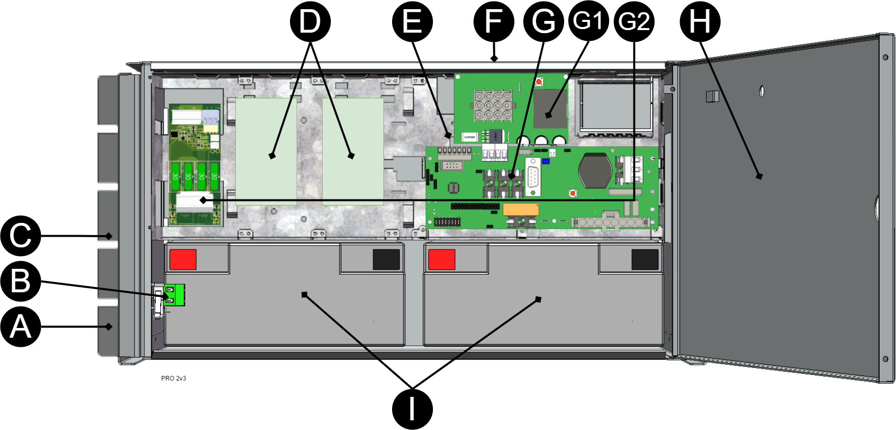
Letter | Explanation |
|---|---|
A | Bracket, reversible for wall mounting or 19 "rack. |
B | Sabotage contact. If alarm class 3 (SSF) is to be met, the tamper switch must be on the wall. |
C | Cabinet in powder-coated sheet metal. |
D | [sv] Plats för fördelningskort. |
E | Power supply. |
F | Cable entries. |
G | Motherboard. |
G1 | Effect card. |
G2 | Load card. |
H | Lockable door. |
I | Space for batteries. |
Batteries - placement and connection
Connecting batteries in FLX M
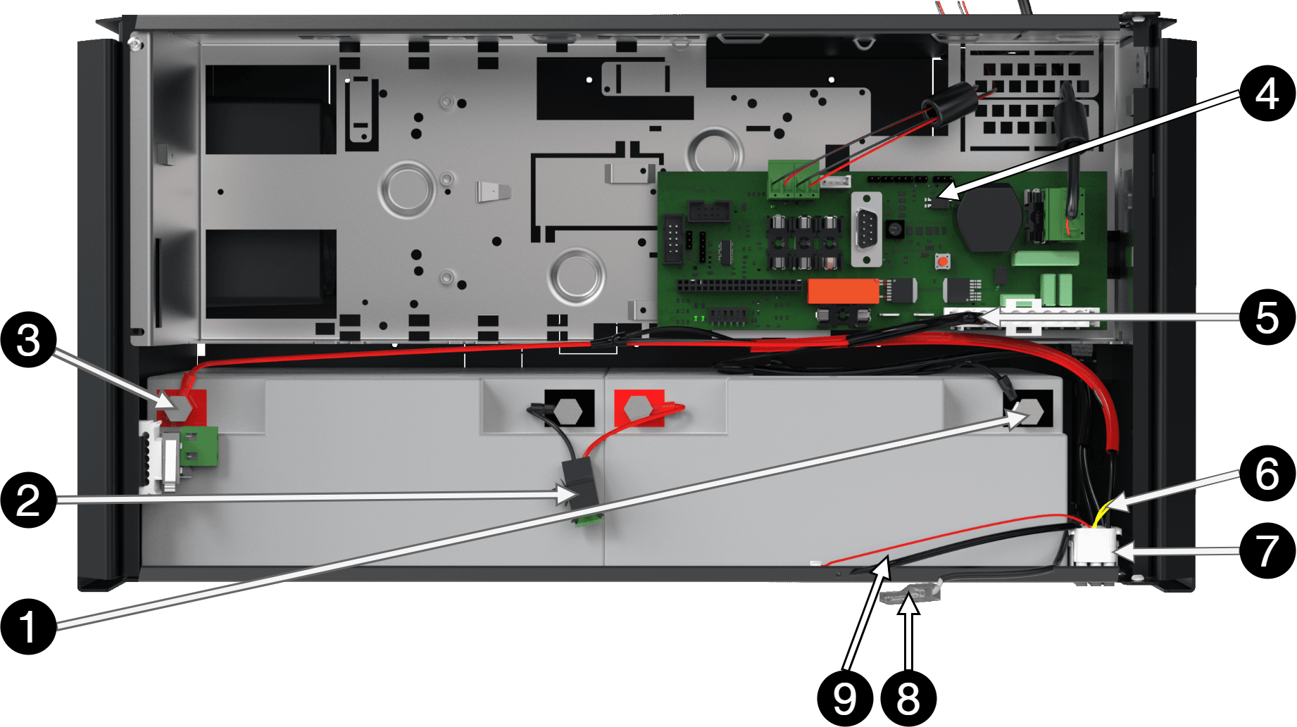
Note that cards (4) differ from different configurations.
No | Explanation |
|---|---|
1 | Minus coil for battery cable from 4. |
2 | Fuse. |
3 | Plus terminal for battery cable from 4. |
4 | Motherboard, varies with configuration. |
5 | Battery cables are located on the system board. |
6 | Yellow cable, which must be cut when connecting the battery box. |
7 | Connection for connection of battery box. |
Connect battery fuse / blade fuse
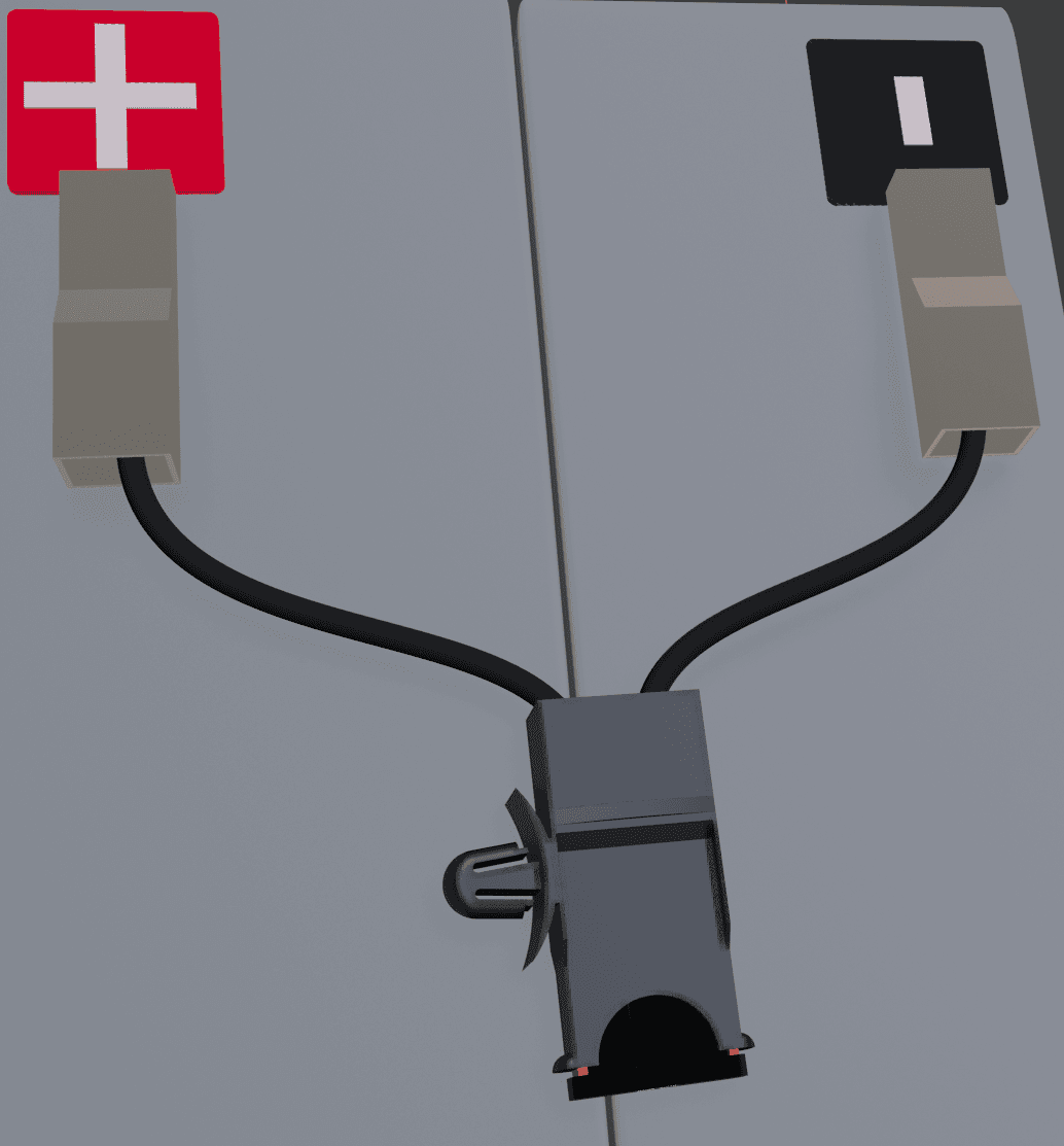
Connection of batteries in FLX S, FLX M and FLX L
Battery wiring is mounted on the circuit board upon delivery. Pictures below only show how to connect wiring.
Place the batteries in the cabinet with the battery terminals facing outwards.
Connect the battery cable. Red cable on + and black cable on -.
If possible, disconnect mains voltage when replacing the battery.
Connect the terminals correctly so that you do not damage the equipment.
PCB description of PRO2v3
The motherboard controls the device, distributes power and communicates with other systems. See technical data for more information.
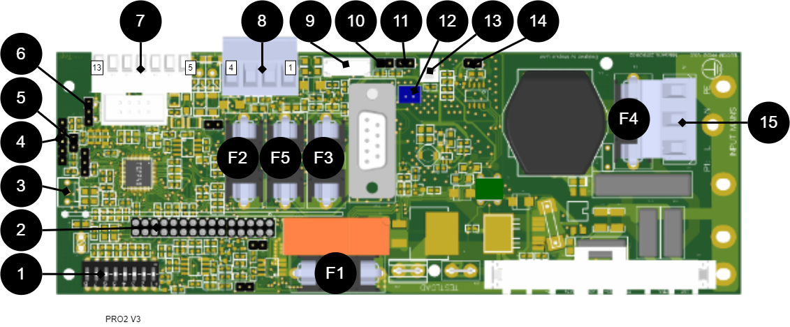
No . | On circuit board | Explanation |
|---|---|---|
1 | Dip SW | Dip switch 1-8 |
2 | J20 | Connection relay board. |
3 | JU17 | Connection external indicator diode. |
4 | - | Programming contact. |
5 | J13 | Reset of data after battery replacement. |
6 | J6 | Temperature sensor. |
7 | P2:7-13 7-8 9-10 11 12 13 | Connection communication. RS-485 GND, Protective earth RX TX +5V |
8 | P2:1-4 1 2 3 4 | Load outputs. + - + - |
9 | J29 | Connection to fan. |
10 | J14 | Tamper switch connection. |
11 | J3 | Connection tamper switch from battery box. |
12 | J1 | Connection option card. |
13 | J4 | Connection external fuse (NO). |
14 | J7/21 | Connection to external fuse (NC). |
15 | P1:1-3 | Incoming mains, (230 V). L, N, PE. |
Fuses
Fuse | Type | Explanation |
|---|---|---|
F1 | T16A | Mains fuse |
F2 | T250m | Load fuse 2 + (for P2: 4) |
F3 | T250mA | Reading protection 1 + (for P2: 1) |
F4 | T4A | Mains fuse. |
F5 | T16A | Load fuse 1+ (for P2: 2) |
Warning for replacing fuses (current strength, A)
There is a risk of damage if the fuse is changed to a larger one than what the unit is delivered with. The function of the fuse is to protect the connected load and cables against damage and fire. It is not possible to change the fuse to a larger one to increase the power output.
Connect the mains to the motherboard (PCB)
Connect mains
Pull wiring through the cable entry on the cabinet.
If possible, secure the mains cable with cable ties where possible.
Electrical network cabling shall be kept separate from other cabling to avoid EMC interference.
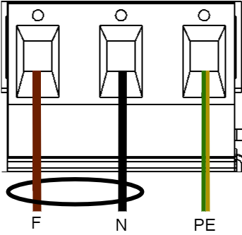
Connect the mains cable to the terminal before it is put back on the motherboard. Secure F and N with cable ties for electrical safety.
Letter | Explanation |
|---|---|
F | Phase |
N | Neutral |
PE | Protective earth |
Electrical mains connection 230 V AC on circuit board
Check that the marking on the circuit board matches the cable arrangement on the terminal block.
Connect load
Max current
The maximum current must not be exceeded. Max current is indicated on nameplate on the device.
Load outputs when SSF certified
In order for certificates to be maintained, only one load output must be used.
If there are one or more connection cards (to increase the number of load outputs), load must be connected there and not on the main board.
Circuit board number | Explanation |
|---|---|
P2: 1 | Connection for load 1 + |
P2: 2 | Connection for load 1 - |
P2: 3 | Connection for load 2 + |
P2: 4 | Connection for load 2 - |
Caution
Load may only be connected to the motherboard in 5 A and 10 A units. For other units, load must be connected via power board or option board.
Connection of load 15 A - 25 A units
For units with a effect card, which is available to handle the higher currents (15 ampere and above), the load must be connected on an optional board.
See documentation for option board for how to connect load.
Warning
Load must not be connected to the motherboard if the device is a 15 A or 25 A, as it will be destroyed during commissioning. Motherboards that are faulty due to incorrect connections are not covered by warranty.
The effect card increases the current for 15 A and 25 A units.
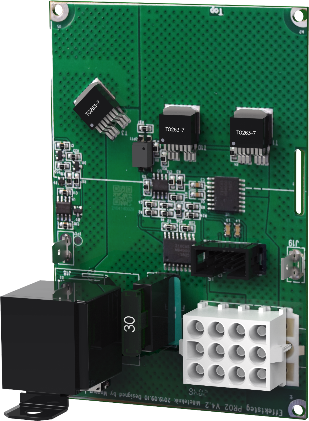
Load cards with blade fuses
The card replaces the load output on the motherboard.
The load card has a different type of fuse that is easier to change and at the same time the card provides a easier connection of the load.
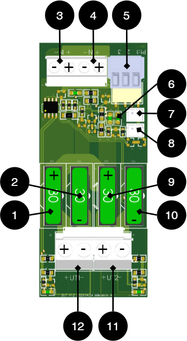 |
No . | On circuit board | Explanation |
|---|---|---|
1, 9 | FUS2, FUS4 | + fuse, 10 A- 25 A depending on the product. |
2, 10 | FUS1, FUS3 | - fuse, 30A. |
3, 4 | IN1, IN2 | Incoming connection 24 V, (from motherboard). |
5 | P1:1-3 | Alarm relay: NC, Com, NO |
6 | D29, D30 | LED. |
7 | J1 | Fuse alarm. |
8 | J2 | Fuse alarm for forwarding to several cards. |
11, 12 | +UT1-, +UT2- | Load connection, outgoing, 24 V |
Load is connected to 11 or 12 on fuse card, see component overview.
Alarm via communication
Connection of communication to the parent system takes place via JU6. See the parent system documentation for more information.
Communication to a parent system
It is possible to connect communication to a superior system via connections on P2. See also the parent system's documentation for compatible protocol. See technical data for more information on alarms.
Terminal block | Explanation |
|---|---|
P2: 7 | RS-485 - |
P2: 8 | RS-485 + |
P2: 9 | System minus - |
P2: 10 | System-minus - |
P2: 11 | RXD |
P2: 12 | TXD |
P2: 13 | +5 V |
Dip switch 1-8
Dip-Switch has several different modes:
Dip switch | In mains operation or in battery operation | Comment |
|---|---|---|
1 | Address for external communication. | - |
2 | Address for external communication | - |
3 | Address for external communication | - |
4 | Address for external communication | - |
5 | Sets alarm for mains failure delay | Available from software v1.5 |
6 | Sets alarm for mains failure delay | Available from software v 1.5 |
7 | Sets alarm limit for low battery voltage in battery operation. | Available from software v 1.5 |
8 | Turns LED off or on. | Upcoming feature through software update |
8 in sequence | Performs battery test | Not available in NEO. |
Address setting for external communication (Dip switch 1-4)
Dip-Switch S1: 1-4 sets addressing.
Dip: 1 | Dip: 2 | Dip: 3 | Dip:4 | |
|---|---|---|---|---|
Adress 1 | ON | OFF | OFF | OFF |
Adress 2 | OFF | ON | OFF | OFF |
Adress 3 | ON | ON | OFF | OFF |
Adress 4 | OFF | OFF | ON | OFF |
Adress 5 | ON | OFF | ON | OFF |
Adress 6 | OFF | ON | ON | OFF |
Adress 7 | ON | ON | ON | OFF |
Adress 8 | OFF | OFF | OFF | ON |
Adress 9 | ON | OFF | OFF | ON |
Adress 10 | OFF | ON | OFF | ON |
Adress 11 | ON | ON | OFF | ON |
Adress 12 | OFF | OFF | ON | ON |
Adress 13 | ON | OFF | ON | ON |
Adress 14 | OFF | ON | ON | ON |
Adress 15 | ON | ON | ON | ON |
Mains failure delay (dip 5-6)
It is possible to change the time for when the alarm for a power outage should be given. Use the matrix to set the alarm.
Alarms for mains failure are given after: | Dip 5 | Dip 6 |
|---|---|---|
3 seconds | OFF | OFF |
30 minutes | ON | OFF |
60 minutes | OFF | ON |
240 minutes (4 hours) | ON | ON |
Low battery voltage (dip 7)
Dip: 7 has the same function regardless of whether the unit is in mains or battery operation or whether the tamper switch is held down.
Alarm for low battery voltage is given when | Dip 7 |
|---|---|
22,8 V* | ON |
24 V | OFF |
*25% of battery capacity remains. | |
LED (dip 8)
LED/battery-test always lights up when the door is open.
Dip-switch 8=ON turns off the LED.
Dip-switch 8=OFF turns on the LED.
Notice
For certified units:
To comply with SSF-1014 up to alarm class 4, the LED on the door must be off (Dip-switch 8 to ON).
Battery test (dip 8)
To do a battery test, dip 8 needs to change position and five seconds need to pass before the test is initiated.
If dip 8 in original position is on OFF then switch dip 8 to: ON (wait 5 seconds) and then switch back to OFF.
If dip 8 in original position is on ON then switch dip 8 to: OFF (wait 5 seconds) and then switch back to ON.
This activates the battery test after 3-8 seconds. The battery test lasts for about 6 seconds and then the LED flashes yellow quickly. Aged battery alarms may be indicated while the battery test is being performed.
Only reset dip 8 when the test is complete.
Reboot to confirm changes in address, battery and alarm settings to parent system
After the dip-switch has been set for various parameters, the device's software needs to be restarted. This is for the new settings to be stored and take effect.
Important
Rebooting according to this procedure does not interrupt the output voltage.
Restarting the device software is done by jumpering J13 (PRO2)
Important
Reboot must be done every time a change is made to the device.
NEO cannot be connected to communication/UC.
Alarm card for PRO2
Relay card - description, connections and alarm outputs.
All fault arm relays must be in the drawn state. Check that there is a gap between CO and NC. Put the measuring instrument on continuity measurement and test closure. This should then indicate a short circuit.
All relay outputs are normally live and give an alarm in the event of no voltage.
Important
There is normally a 10 second delay in alarm reset. The software on the main board must be configured for a different time period.
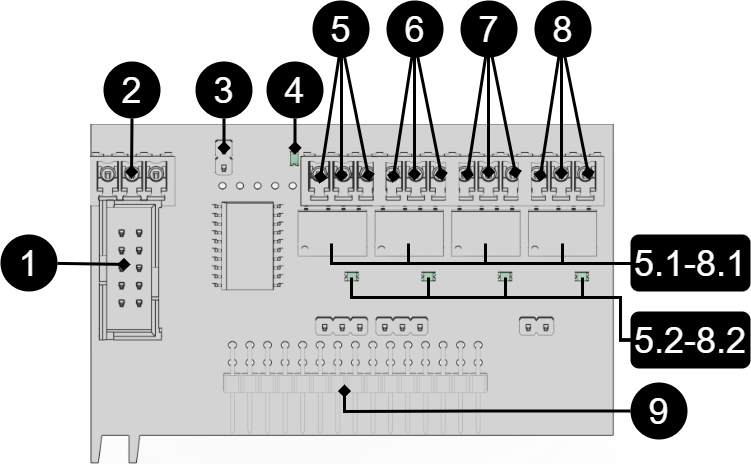 |
No . | Relay (Terminal no.) | The relay is normally energized. | Alarm type / explanation |
|---|---|---|---|
1 | J7 | - | Connection for RS-232 cable. |
2 | P4:1 | - | RS-232: TxD, data OUT from motherboard. |
P4:2 | - | RS-232: RxD, data IN to motherboard. | |
P4:3 | - | RS-232: Ground, do not connect ground to another terminal. | |
3 | J6 | - | Reset jumper. |
4 | D7 | - | Indicator diode, flashes green during normal operation. |
5,5.1, 5.2 | P5:1-3 | NO, COM, NC | Tamper alarm, (optional for EN54). 5.1 Relay. 5.2 LED, lights up green when relay is energized. |
6, 6.1, 6.2 | P5:4-6 | NO, COM, NC | Alarm for: Low system voltage. 6.1 Relay. 6.2 LED, lights up green when relay is energized. |
7, 7.1, 7.2 | P5:7-9 | NO, COM, NC | Alarm for: Fuse failure, charger failure overvoltage, charger failure undervoltage, cell failure/not connected battery, low battery voltage in case of mains failure and aged battery. 7.1 Relay. 7.2 LED, lights up green when relay is energized. |
8, 8.1, 8.2 | P5:10-12 | NO, COM, NC | Power failure alarm. 8.1 Relay. 8.2 LED, lights up green when relay is energized. |
9 | J11 | - | Connection to motherboard. |
Via communication on PRO1 card: All alarms and alarms for: Fan fault, overtemperature, subtemperature, short battery life left, overcurrent 100% of minute average, overcurrent 80% daily average and overcurrent 175% second average. | |||
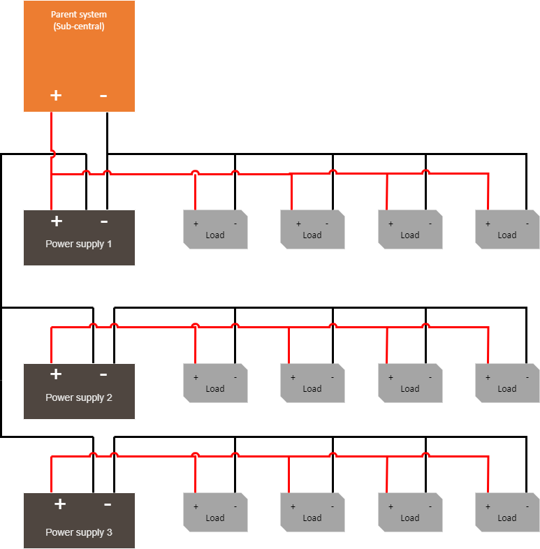
Multiple units into one parent system
To connect several units to a higher system, the load-minus between several battery backups must be connected together.
 |
Commissioning - how to start the unit
Connect batteries
Connect / switch on fuses
connect load, alarm and possibly. other connections.
Screw the mains cable into the terminal block and attach the terminal block to the motherboard.
Switch on mains voltage.
Connect in this order
To minimize the risk of errors that may occur in connection with a short circuit, connections to the motherboard must be made in this order.
The unit works normally when the indicator LED on the outside of the cabinet door lights up with a solid green light. See front panel for other status indications.
It may take up to 72 hours before the batteries are fully charged.
72 hours after commissioning / battery change
For the first 72 hours after commissioning, the device does not perform a battery capacity test. The test is postponed so that the device does not falsely alarm before the batteries are charged. The unit must always be started with new batteries when commissioning or changing batteries and it is unlikely that new batteries are faulty.
System test
Test the connected device by performing a system test afterwards commissioning.
Important
Let the batteries charge for a couple of hours, use a multimeter to measure the voltage on each battery. The voltage must be at least 12.7 V per battery.
Switch on incoming mains voltage.
Indicator LED on the outside of the cabinet door lights up with a solid green light. Disconnect the mains voltage to check that the unit is operating in battery mode and alarms.
LED on the cabinet door indicates, see panel for alarm type.
Switch on incoming mains voltage. Indicator LED, on the outside of the cabinet door, lights up with a solid green light. Normal operation.
Recovery
Reset the unit by completely de-energizing the unit.
Disconnect battery wiring and mains voltage and reconnect after 5 seconds.
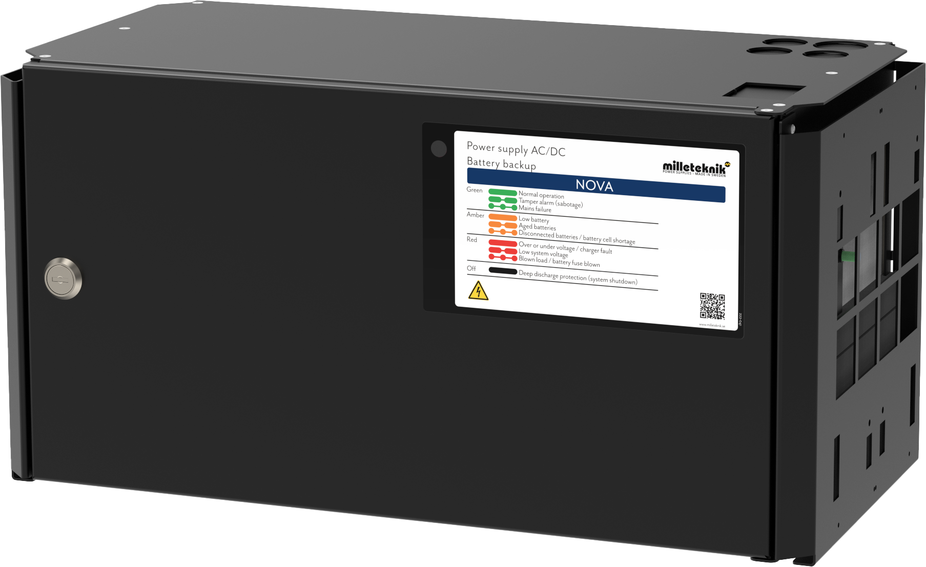
Alarm displayed on cabinet door
In normal mode, the indicator LED shows a solid green light.
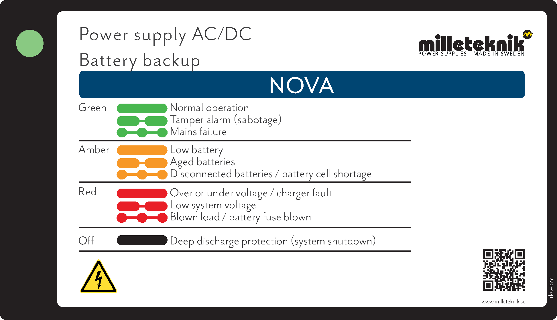 |
The indicator diode (LED) shows | Explanation |
|---|---|
Solid green light | Normal operation. |
Slow green flashes | Sabotage alarm. |
Fast green flashes | Mains failure. |
Solid yellow light | Low battery voltage. |
Slow yellow flashes | Aged batteries. |
Rapid yellow flashes | Disconnected batteries or battery cell shortage. |
Solid red light | Overvoltage or undervoltage or charger fault. |
Slow red flashes | Low system voltage. |
Rapid red flashes | Blown load or battery fuse has blown. |
No light / off | Deep discharge protection is activated. (System shutdown). |
When operating system: If the indicator LED is off, deep discharge protection has come into force.
Adjustment of tamper switch
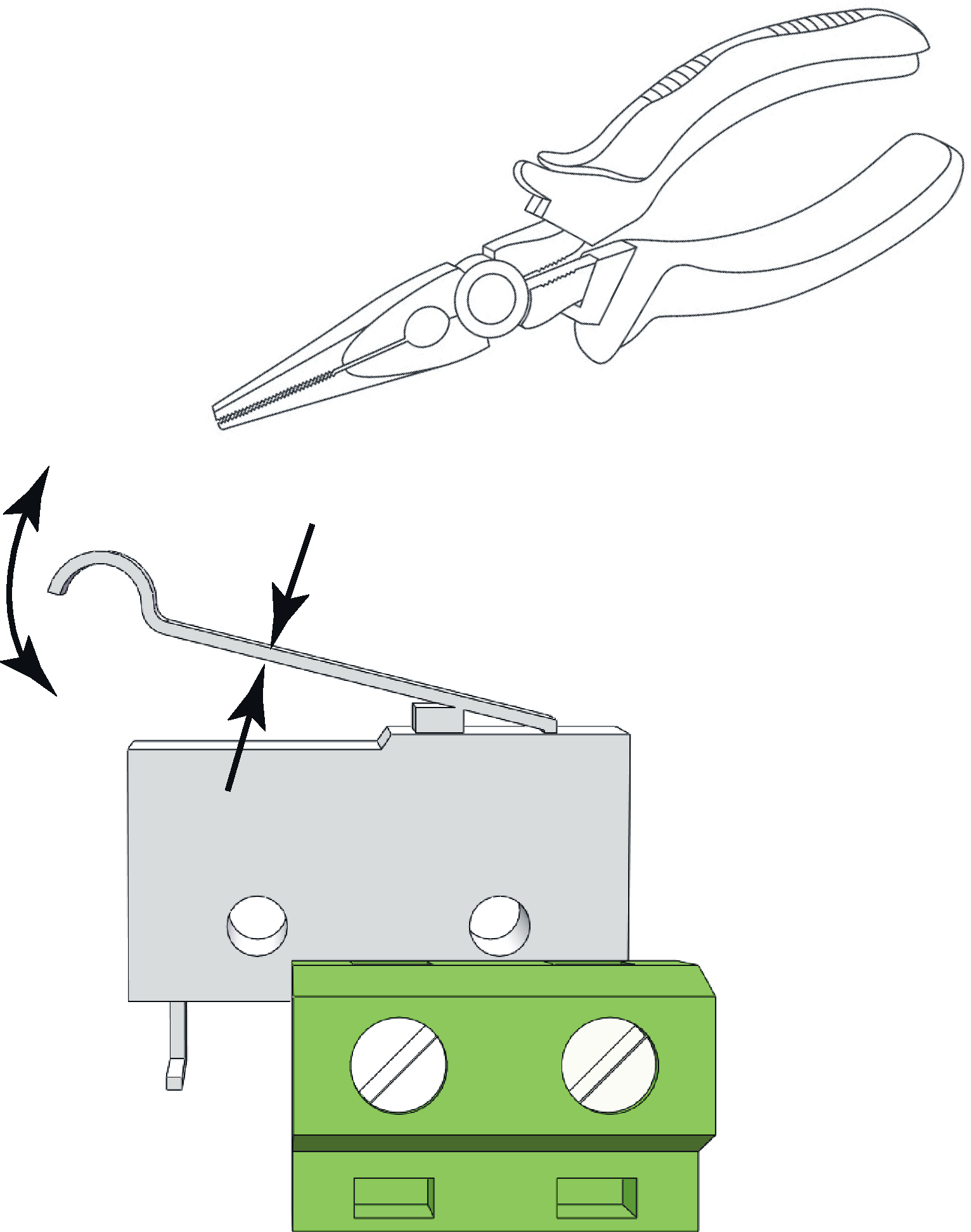 |
The tamper switch lever must be in the closed position when the cabinet door is closed. If the alarm goes off ("tamper alarm"), the lever may needs to be adjusted.
The lever is adjusted by the following steps:
Pinch with pliers in the middle of the lever.
Carefully adjust the lever in the desired direction (up / down).
Check by closing the door. A click is heard when the contact is closed.
Notice
Tamper switch will not give an alarm when closed and locked the door.
Maintenance
The system with the exception of batteries is maintenance-free when installed in an indoor environment.
Check the fan annually. The fan should rotate smoothly without any noise. Clean the fan from dust and dirt. The fan must be replaced if it does not rotate smoothly or is so dirty that it cannot be completely cleaned. If the fan does not work well, the air flow in the unit will be obstructed, which leads to an increase in heat in the enclosure, which can lead to a deterioration of the battery capacity and to a significantly shorter battery replacement interval.
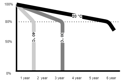
About batteries
Batteries generate electricity through a chemical process and there is thus a natural degradation of capacity. The biggest factor in battery life is temperature. The higher the temperature, the shorter the battery life. The date of manufacture stamped on the battery and the service life (as stated by the battery manufacturer). An ideal temperature is 20 °C both in operation and in storage. Higher ambient temperature greatly reduces the service life. Thus, actual lifespan varies when used. Batteries should be replaced after half specified (from the battery manufacturer) lifetime for safe operation. Batteries purchased through the manufacturer of the battery backup have a lifespan (from the battery manufacturer) of between 10-12 years with recommended replacement after 5-6 years.
battery change
If possible, disconnect mains (voltage) when replacing the battery.
Disconnect battery cables. Note how battery cables are mounted before removing them.
Remove battery fuse between batteries.
Insert and fasten the new batteries.
Connect the battery cables in the same way as before.
Connect battery fuse between batteries.
Switch on mains voltage. The indicator LED may not be green (up to 72 hours), until the batteries are charged.
Test the system by briefly disconnecting the mains voltage, (= the load is driven by the batteries), and then switch on the mains voltage again.
Battery recycling
All batteries must be recycled. Return to manufacturer or return to recycling station.

NOVA product sheet
SSF1014 certified battery backup with communication
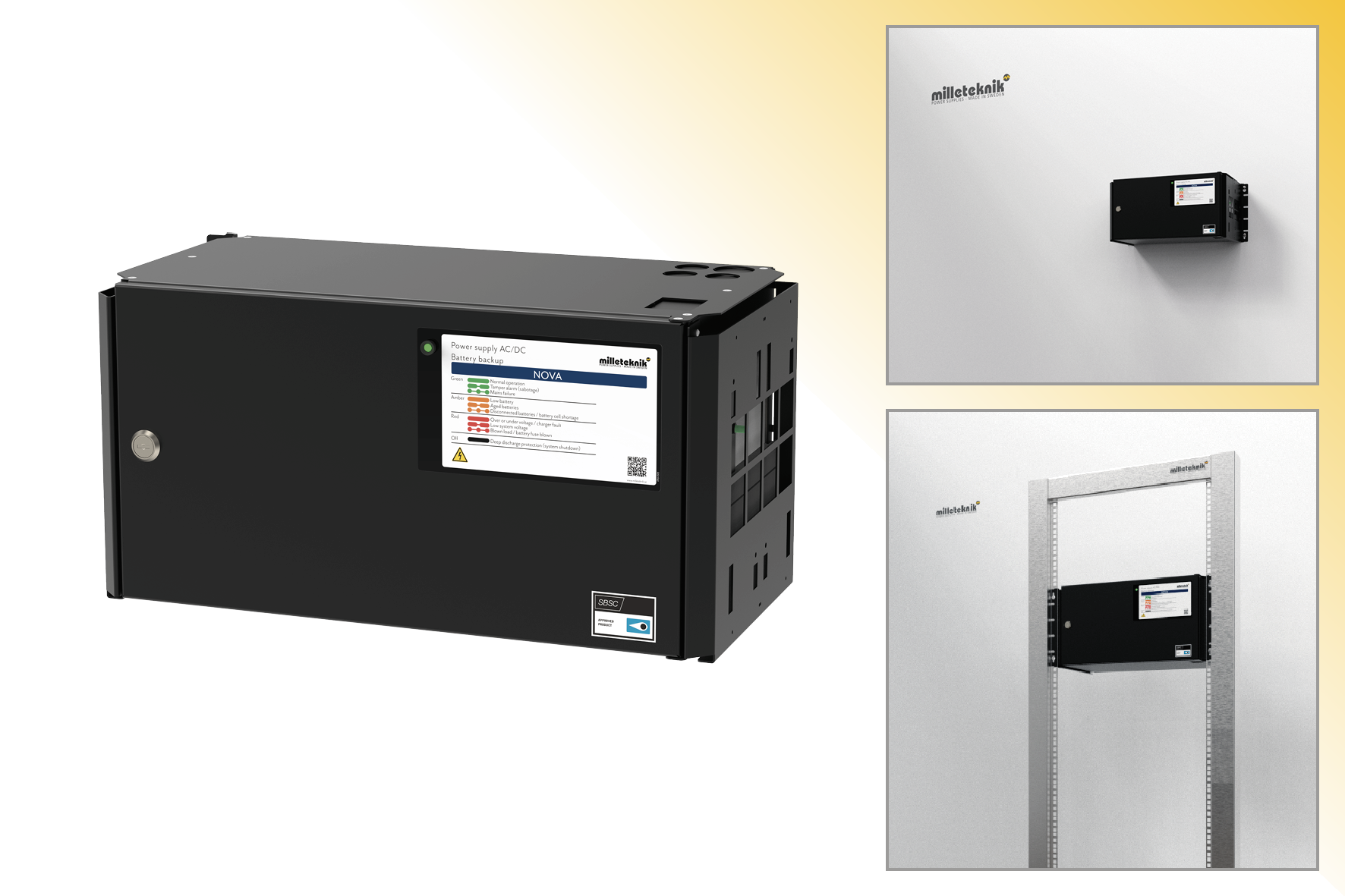 |
NOVA FLX M can be mounted on a wall or in a 19" rack.
Technical specifications
These technical specifications are subject to change without notice.
Name, article number and e-number
Name | Article number | E-number |
|---|---|---|
NOVA 24V 15A FLX M | FM01P23024P150-SSF | 52 136 39 |
NOVA 24V 25A FLX M | FM01P23024P250-SSF | 52 136 40 |
About NOVA FLX
NOVA FLX is mainly used in safety systems where SSF 1014 approved battery backup is required or where the requirements are higher. Requirements such as better flexibility, more alarm functions, longer backup operating times or where the battery backup needs to handle higher loads.
The NOVA series is system certified according to SSF1014 together with most systems on the Swedish market. Milleteknik has the right to sell two different systems on the Swedish market; Sentrion NOVA The series has communication via RS485 to Sentrion S4, S4 DUO and CISS. Integra. Together with MOVEO kit (optional) there is RS232 communication with Integra MOVEO and MOVEO XL.
Flexibility
NOVA FLX S can have an extra battery box. NOVA FLX M and NOVA FLX L with 1-4 extra battery boxes *. NOVA FLX M and NOVA FLX L with battery shelves in 19 ”rack *. * The battery boxes and shelves are connected via a 9-pin connector. The battery box has room for up to 2 pcs. 45 Ah batteries per battery box. Battery shelves have room for 2 pcs. 45 Ah batteries (Medium) and up to 2 pcs. 150 Ah batteries (Large) per each battery shelf.
Fixed installation
The product is intended for fixed installation. The battery backup must be installed by a qualified installer.
Area of use
NOVA FLX mostly used for: Access control system, burglar alarms, (integrated security systems), in public environments such as schools, offices and commercial properties.

The unit meets the requirements for installation in systems that must be SSF 1014 approved. SSF 1014 certificate is only valid for certification together with a higher-level system.
Important
In order for the SSF 1014 certificate to be valid, only one (1) load output may be used.
Installation video

Regulations and certifications
Standards that product (s) meet and are approved for
SBF 110:8 |
SSF1014 Alarm class 1-4 (burglar alarm). |
SSF1014, Issue 5. |
Certificate number, SBSC | Designation SBSC |
|---|---|
No. 18-246 | NOVA 27 250-FLX, NOVA 27 150-FLX, NOVA 27 100-FLX, NOVA 27 50-FLX, NOVA 13 100-FLX, NOVA 27 100-XS2, NOVA 27 50-XS2, NOVA 27 30-XS2, NOVA 13 100-XS2, NOVA 13 50-XS2 |
No. 20-117 | NOVA 27 50-FLX S • NOVA 27 100-FLX S • NOVA 27 50-FLX M • NOVA 27 100-FLX M • NOVA 27 150-FLX M • NOVA 27 250-FLX M • NOVA 27 50-FLX L • NOVA 27 100-FLX L • NOVA 27 150-FLX L • NOVA 27 250-FLX L Unison Facility Cabinet |
Certificate number, RiSE |
|---|
SC0204-19 |
Requirements that the product meets
EMC: | EMC Directive 2014 / 30EU |
CE: | CE directive according to: 765/2008 |
Emission: | EN61000-6-: 2001 EN55022: 1998: -A1: 2000, A2: 2003 Klass B, EN61000-3-2: 2001 |

Reserve operating times, power outlet and load output current
Charging current for batteries and battery capacity
The unit reads the connected system load and charges the batteries with available residual current from the power supply. The device performs qualified* battery tests and notifies when batteries need to be replaced. The batteries are charged gently to extend their life and protection is available against overcharging.
12 V / 24 V | Maximum charging current for batteries |
|---|---|
NOVA FLX M | 6 A |
The battery backup has controlled charging ** (controlled charging) which prevents batteries from being overcharged and extends their service life significantly. The NOVA series must be used with AGM batteries.
24 V | Battery capacity | Maximum battery capacity with 1 battery box | Maximum battery capacity with 2 battery boxes | Maximum battery capacity with 3 battery boxes | Maximum battery capacity with 4 battery boxes |
|---|---|---|---|---|---|
NOVA FLX M, 24 V | 20 Ah (2 x 20 Ah | 65 Ah (4 x 20 Ah) | 110 Ah (2 x 20 Ah + 2 x 45 Ah) | 155 Ah (6 x 20 Ah + 2 x 45 Ah) | 200 Ah (2 x 20 Ah + 8 x 45 Ah) |
* Battery test is done with power resistor and the unit is tested and certified together with UPLUS 10+ Design life AGM batteries according to SSF1014. It is these batteries that must be used to maintain the certificate.
** Controlled charging means that when the batteries are fully charged, they will be disconnected electronically for standby mode for up to 20 days or when the batteries have reached 26.7 V (24 V). By discharging the batteries and charging them continuously (instead of never using them), the system extends the battery life by up to 50%. The batteries connect automatically in less than 50 microseconds.
Power outlet NOVA FLX
NOVA 24V 15A FLX M | Unit without battery box | Unit with 1 battery box | Unit with 2 battery boxes | Unit with 3 battery boxes | Unit with 4 battery boxes |
|---|---|---|---|---|---|
Battery | 2 st 20 Ah | 2 st 45 Ah / 2 st 20 Ah + 2 st 45 Ah | 4 st 45 Ah / 2 st 20 Ah + 4 st 45 Ah | 64 st 45 Ah / 2 st 20 Ah + 6 st 45 Ah | 8 st 45 Ah / 2 st 20 Ah + 8 st 45 Ah |
Max battery capacity | 20 Ah | 45 Ah / 65 Ah | 90 Ah / 110 Ah | 135 Ah / 155 Ah | 180 Ah / 200 Ah |
According to. SSF1014, Alarm Class 1-2 | 1.5 A | 3.6 A / 5.2 A | 7.3 A / 9.0 A | 11.1 A / 12.7 A | 14.8 A / 16.5 A |
According to. SSF1014, Alarm Class 3-4 | 0.55 A | 1.4 A / 2.0 A | 2.9 A / 3.5 A | 4.4 A / 5.0 A | 5.9 A / 6.5 A |
Imax A (max discharge current) | 15 A | 13 A / 13 A | 13 A / 13 A | 13 A / 13 A | 13 A / 13 A |
Imax b (max charging current) | 15 A | 15 A / 15 A | 15 A / 15 A | 15 A / 15 A | 15 A / 15 A |
Imin is always 0 A. | |||||
Not all devices may be certified, see device certificate. | |||||
NOVA 24V 25A FLX M | Unit without battery box | Unit with 1 battery box | Unit with 2 battery boxes | Unit with 3 battery boxes | Unit with 4 battery boxes |
|---|---|---|---|---|---|
Battery | 2 st 20 Ah | 2 st 45 Ah / 2 st 20 Ah + 2 st 45 Ah | 4 st 45 Ah / 2 st 20 Ah + 4 st 45 Ah | 64 st 45 Ah / 2 st 20 Ah + 6 st 45 Ah | 8 st 45 Ah / 2 st 20 Ah + 8 st 45 Ah |
Max battery capacity | 20 Ah | 45 Ah / 65 Ah | 90 Ah / 110 Ah | 135 Ah / 155 Ah | 180 Ah / 200 Ah |
According to. SSF1014, Alarm Class 1-2 | 1.5 A | 3.6 A / 5.2 A | 7.3 A / 9.0 A | 11.1 A / 12.7 A | 14.8 A / 16.5 A |
According to. SSF1014, Alarm Class 3-4 | 0.55 A | 1.4 A / 2.0 A | 2.9 A / 3.5 A | 4.4 A / 5.0 A | 5.9 A / 6.5 A |
Imax A (max discharge current) | 25 A | 25 A / 25 A | 25 A / 25 A | 25 A / 25 A | 25 A / 25 A |
Imax b (max charging current) | 30 A | 30 A / 30 A | 30 A / 30 A | 30 A / 30 A | 30 A / 30 A |
Imin is always 0 A. | |||||
Not all devices may be certified, see device certificate. | |||||
Permitted average load according to SSF1014 Alarm class 1-4:
Permitted average load according to SSF1014 Alarm class 1-4: | NOVA 24V 5A FLX M | NOVA 24V 10A FLX M | NOVA 24V 25A FLX M | NOVA 24V 25A FLX L |
|---|---|---|---|---|
FLX M without battery box according to Alarm class 1-2 / 3-4 | 1.6 A / 0.55 A | 1.6 A / 0.55 A | 1.6 A / 0.55 A | 1.6 A / 0.55 A |
Including 1 pc. Battery box FLX M, according to Alarm class 1-2 / 3-4: | 3.7 A / 1.5 A | 3.7 A / 1.5 A | 3.6 A / 1.4 A | 3.6 A / 1.4 A |
Including 2 pcs. Battery box FLX M, according to Alarm class 1-2 / 3-4: | - | 7.4 A / 3A | 7.3 A / 2.9 A | 7.3 A / 2.9 A |
Including 3 pcs. Battery box FLX M, according to Alarm class 1-2 / 3-4: | - | - | 11.1 A / 4.4 A | 11.1 A / 4.4 A |
Including 4 pcs. Battery box FLX M, according to Alarm class 1-2 / 3-4: | - | - | - | 14.8 A / 5.9 A |
Reserve operating times for different alarm classes - overview
Alarm class | Spare operating time in the event of a power failure | Maximum number of hours of battery recharging (80%) |
|---|---|---|
EN54-4 | - | 24 h |
SBF110: 8 | 30 h + 10 min | 24 h |
EN50131-6 grades 1-2 | 12 h | 72 h |
EN50131-6 grade 3 | 24 h | 24 h |
SSF1014 Alarm class 1/2 | 12 h | 72 h |
SSF1014 Alarm class 3/4 | 30 h | 24 h |
The table shows the requirements for backup operating time and recharging of batteries for different alarm classes.
About translation of this document
User manual and other documents are in the original language in Swedish. Other languages may be machine translated and/or not reviewed, errors may occur.
Circuit boards - Technical data
Technical data, motherboard: PRO 2 V3
Info | Explanation |
|---|---|
Short name: | PRO 2 V3 |
Product description | Motherboard in battery backup with advanced functions and communication to parent system. |
Own consumption, with relay card | Less than 210 mA. 100 mA without power stage with all relays retracted on external alarm card in normal mode. |
Switching time from mains voltage to battery operation | When batteries are idle: <5 microseconds. When batteries are in charge cycle: 0 (none). Batteries rest for 20-day cycles, after which a charging cycle picks up and charges the batteries for 72 hours. If there is a power failure when batteries are in the charge cycle, there is no switching time. |
Incoming electricity network | 230 V AC -240 V AC, 47-63 Hz. |
Fuse on mains | See table: Fuses. |
Indication | Indicator diode on circuit board / cabinet door |
Alarm
Alarm displayed on indicator LED on the front of the cabinet.
Cell fault in battery or unconnected battery.
Charger fault, undervoltage.
Charger fault, overvoltage.
Low system voltage, system voltage below 24.0 V in mains operation.
Low battery voltage, below 24.0 V DC in case of mains failure.
Power failure alarm.
Sabotage switch.
Fuse fault.
Aged battery
Expanding alarm functions are available via communication or with alarm cards.
Info | Explanation |
|---|---|
Alarm on alternating relay? (Yes No) | Yes |
Alarm output protocol (communication protocol) | RS-485 and I2C |
Load outputs, number | 2 |
Voltage at load output | 27.3 V DC |
Voltage limit, upper, on load output | 27.9 V DC |
Voltage limit, lower, on load output. For battery operation and disconnected mains voltage. | 20 V DC |
Priority (always voltage) load outputs (Yes / No) | - |
Maximum load, per output | 10 A |
Maximum load, total, (must not be exceeded). | 10 A |
Load output plus (+) secured? (Yes No) | - |
Load output minus (-) secured (Yes / No) | - |
Fuses on output | Yes, see table: Fuses. |
Connection to buzzer? (Yes No) | - |
Fuses | Type |
|---|---|
1.5 A | F1.5A |
3 A | T3A |
5 A | T5A |
10 A | T10A |
15 A | T15A |
25 A | T25A |
Power supply fuse of 12V one | T2.5AH250V. Ceramic. |
Mains fuse for 24 V units up to 15 A | T2.5AH250V. Ceramic. |
Mains fuse for 24 v units over to 15 A | T4AH250V. Ceramic. |
Info | Explanation |
|---|---|
Deep discharge protection (Yes / No) | Yes. 12 V units protection at 10V, +/- 0.5 V. 24 V units protection at 20, +/- 0.5 V. |
Surge protection (Yes / No) | Yes |
Overtemperature protection (Yes / No) | Yes |
Short circuit protected = (Yes / No) | Yes |
Technical data, alarm cards for PRO 2 and PRO2 V3
Info | Explanation |
|---|---|
Card name: | PRO2 larmkort |
Version: | 2.0 |
Product description | Alarm card for PRO2 and PRO2 V3 with alarm on alternating relay. All relays are normally energized and give an alarm in a voltage-free position. |
self-consumption | 40 mA |
Alarm overview in alphabetical order | Relay 1 * / Alarm output 1 | Relay 2 * / Alarm output 2 | Relay 3 * / Alarm output 3 | Relay 4 * / Alarm output 4 | Communication (P1: 1-12) | Indicator LED on motherboard and LED on door. |
|---|---|---|---|---|---|---|
Network outages | X | - | - | - | X | X |
Fuse fault | - | X | - | - | X | X |
Sabotage switch | - | - | - | X | X | X |
Fan fault | - | - | - | - | X | - |
Charger fault, overvoltage | - | X | - | - | X | X |
Charger fault, undervoltage | - | X | - | - | X | X |
Cell fault or unconnected battery | - | X | - | - | X | X |
Low system voltage. ** | - | - | X | - | X | X |
Low battery voltage (<24.0 V DC) or power failure | - | X | - | - | X | X |
Overtemperature | - | - | - | - | X | - |
Undertemperature | - | - | - | - | X | - |
Undertemperature | - | - | - | - | X | - |
Short battery life left | - | - | - | - | X | - |
Aged battery | - | X | - | - | X | X |
Overcurrent 100%, minute average | - | - | - | - | X | - |
Overcurrent 80%, daily average | - | - | - | - | X | - |
Overcurrent 175%, second average | - | - | - | - | X | - |
* Alarm on potential-free relay contact.
** System voltage in mains operation is below 24.0 V.
350-232
Power supply
Power supply - Technical Data RSP-320-24
In: |
|---|
NOVA 24V 15A FLX M |
Info | Explanation |
|---|---|
Output voltage | 27.3 V |
Output current | 0 A - 13.4 A |
Output voltage, ripple | 150 mVp-p |
Overvoltage | 27.6 V - 32.4 V |
Voltage recharge, ripple / current limitation | Less than 1.2 Vp-p |
Efficiency | 89% |
Current limitation | 105% - 135% |
Constant voltage | +/- 0.5% |
Regulatory accuracy | +/- 1.0% |
Input current (230 V) | 2 A |
Mains voltage frequency | 47 Hz- 63 Hz |
Mains voltage | 230 V AC - 240 V AC |
Brand effect | 321.6 W |
Temperature range | -30°C - +70°C |
Humidity range | 20% - 90% RH non-condensed |
Power supply - Technical Data HRP-600-24
In: |
|---|
NOVA 24V 25A FLX M |
Info | Explanation |
|---|---|
Output voltage | 27.3 V |
Output current | 0 A - 27 A |
Output voltage, ripple | 150 mVp-p |
Overvoltage | 30 V - 34.8 V |
Voltage recharge, ripple / current limitation | Less than 1.2 Vp-p |
Efficiency | 88% |
Current limitation | 105% - 135% |
Constant voltage | +/- 0.5% |
Regulatory accuracy | +/- 1.0% |
Input current (230 V) | 3,6 A |
Mains voltage frequency | 47 Hz- 63 Hz |
Mains voltage | 230 V AC - 240 V AC |
Brand effect | 648 W |
Temperature range | -30°C - +70°C |
Humidity range | 20% - 90% RH non-condensed |
Technical data enclosures
Enclosures - Technical Data FLX M
Info | Explanation |
|---|---|
Name | FLX M |
Enclosure class | IP 32 |
Measure | Height: 224 mm, width 438 mm, depth 212 mm |
Height units | 5 HE |
Mounting | Wall or 19 "rack |
Ambient temperature | + 5 ° C - + 40 ° C. For best battery life: + 15 ° C to + 25 ° C. |
Environment | Environmental class 1, indoors. 20% ~ 90% relative humidity |
Material | Powder coated sheet |
Color | Black |
Cable entries, number | 4 |
Batteries that fit | 2 pieces 12 V, 20 Ah. |
Fan | Yes |
Link to the latest information
Products and software are subject to updates, you will always find the latest information on our website.
Warranty, support, country of manufacture and country of origin
Warranty 5 years
The product has a five-year warranty, from the date of purchase (unless otherwise agreed). Free support during the warranty period is reached at support@milleteknik.se or telephone, +46 31-34 00 230. Compensation for travel and or working hours in connection with the location of faults, installation of repaired or replaced goods is not included in the warranty. Contact Milleteknik for more information. Milleteknik provides support during the product's lifetime, however, no later than 10 years after the date of purchase. Switching to an equivalent product may occur if Milleteknik deems that repair is not possible. Support may be added (at Millteknik's desrection) after the warranty period has expired.
Manufacturer support
Manufacturers provide support for the life of the product, however, for a maximum of 10 years after the date of purchase. Switching to an equivalent product may occur if the manufacturer deems that repair is not possible. Support costs will be added after the warranty period has expired.
Support
Do you need help with installation or connection?
You will find answers to many questions at: www.milleteknik.se/support
Phone: +46 31-340 02 30
Support is open: Monday-Thursday 08:00-16:00, Fridays 08:00-15:00. Closed 11:30-13:15.
Spare parts
Contacted support for questions about spare parts.
Support after the warranty period
Milleteknik provides support during the life of the product, but no longer than 10 years after the date of purchase. Replacement for an equivalent product may occur if the manufacturer deems that repair is not possible. Costs for support and replacement are added after the warranty period has expired.
Questions about product performance?
Contact sales: 46 31-340 02 30, e-mail: sales@milleteknik.se
Contact us
Milleteknik AB
Ögärdesvägen 8 B
S-433 30 Partille
Sweden
+46 31-34 00 230
www.milleteknik.se
Country of manufacture
Country of manufacture / country of origin is Sweden. For more information, contact your seller.
Designed and produced by: Milleteknik AB
Designed and produced by Milleteknik AB
Product life cycle, environmental impact and recycling
The product is designed and constructed for a long service life, which reduces the environmental impact. The product's service life depends on, among other things, environmental factors, mainly ambient temperature, unforeseen load on components such as lightning strikes, external damage, handling errors, and more. Products are recycled by being handed over to the nearest recycling station or sent back to the manufacturer. Contact your distributor for more information. Costs that arise in connection with recycling are not reimbursed.

Batteries - recommended, not included
Batteries are not included they are sold separately
Batteries are sold separately.
Battery combinations NOVA FLX M
Battery capacity (Ah) | Battery type | Number of batteries | Batteries in unit |
|---|---|---|---|
20 Ah | 20 Ah | 2 pcs | 2 in Battery Backup |
45 Ah | 45 Ah | 2 pcs | 0 in Battery Backup 2 in Battery Box 1 |
65 Ah | 20 Ah + 45 Ah | 4 st | 2 in Battery Backup 2 in Battery Box 1 |
90 Ah | 45 Ah | 4 st | 0 in Battery Backup 2 in Battery Box 1 2 and Batteribox 2 |
110 Ah | 20 Ah + 45 Ah | 6 st | 2 in Battery Backup 2 in Battery Box 1 2 and Batteribox 2 |
135 Ah | 45 Ah | 6 st | 0 in Battery Backup 2 in Battery Box 1 2 and Batteribox 2 2 and Batteribox 3 |
155 Ah | 20 Ah + 45 Ah | 8 st | 2 in Battery Backup 2 in Battery Box 1 2 and Batteribox 2 2 and Batteribox 3 |
180 Ah | 45 Ah | 8 st | 0 in Battery Backup 2 in Battery Box 1 2 and Batteribox 2 2 and Batteribox 3 2 and Batteribox 4 |
200 Ah | 20 Ah + 45 Ah | 10 pieces | 2 in Battery Backup 2 in Battery Box 1 2 and Batteribox 2 2 and Batteribox 3 2 and Batteribox 4 |
Certified with battery type
The device is certified with a UPLUS battery that must be used to maintain the certificate.
20 Ah, 12 V AGM battery
Fits in | Number of batteries |
|---|---|
NOVA 24V 15A FLX M | 2 |
NOVA 24V 25A FLX M | 2 |
Battery type | V | Ah |
|---|---|---|
Maintenance-free AGM, lead-acid battery. | 12 V | 20 Ah |
Article number | E-number | Article name | Terminal | Measure. Height width depth | Weight per piece | Make |
|---|---|---|---|---|---|---|
MT113-12V20-01 | 5230538 | UPLUS 12V 20Ah 10+ Design Life battery | M5 Bult | 182x77x168 mm | 6.0 kg | UPLUS |
Reserve operating times for different alarm classes - overview
The table shows the requirements for backup operating time and recharging of batteries for different alarm classes.
Important
This is a guide and all times are approximate and may differ from actual times. Load, temperature and other factors come into play, which is why exact time can not be provided.
Applies to new batteries.
Amperage and batteries vary with configuration, check if the configuration can handle batteries and amperage.
Medium current | 7.2 Ah | 14 Ah | 28 Ah | 45 Ah |
|---|---|---|---|---|
Loading | Backup operating time (approx.), Minutes | |||
0.5 A | 450 | 820 | 1650 | 2350 |
1 A | 260 | 485 | 970 | 1460 |
2 A | 150 | 280 | 560 | 920 |
4 A | 90 | 165 | 335 | 550 |
6 A | 67 | 125 | 245 | 405 |
8 A | 57 | 105 | 210 | 350 |
10 A | 44 | 80 | 160 | 270 |
12 A | 38 | 70 | 140 | 235 |
14 A | 33 | 60 | 120 | 200 |
16 A | 28 | 50 | 100 | 170 |
18 A | 25 | 45 | 89 | 150 |
20 A | 23 | 42 | 84 | 142 |
Medium current | 28 Ah | 42 Ah | 65 Ah | 70 Ah |
|---|---|---|---|---|
- | 4 batteries (14 Ah) | 6 batteries (14 Ah) | 4 batteries (20Ah + 45 Ah) | 10 batteries (7 Ah) |
Loading | Backup operating time (approx.), Minutes | |||
0.5 A | 1650 | 2090 | 5574 | 3440 |
1 A | 970 | 865 | 3252 | 2118 |
2 A | 560 | 815 | 1770 | 1329 |
4 A | 335 | 490 | 930 | 864 |
6 A | 245 | 360 | 600 | 605 |
8 A | 210 | 310 | 426 | 544 |
10 A | 160 | 240 | 342 | 414 |
12 A | 140 | 210 | 270 | 363 |
14 A | 120 | 180 | 234 | 311 |
16 A | 100 | 150 | 204 | 286 |
18 A | 90 | 130 | 150 | 254 |
20 A | 84 | 126 | 138 | 241 |
Medium current | 90 Ah | 110 Ah | 135 Ah | 155 Ah |
|---|---|---|---|---|
- | 4 batteries (45 Ah) | 6 batteries (20 Ah + 45 Ah) | 6 batteries (45 Ah) | 8 batteries (20 Ah + 45 Ah) |
Loading | Backup operating time (approx.), Minutes | |||
0.5 A | 4705 | 5796 | 7056 | 8215 |
1 A | 2928 | 3582 | 4392 | 5070 |
2 A | 1836 | 2247 | 2754 | 3230 |
4 A | 1183 | 1438 | 1762 | 2018 |
6 A | 788 | 959 | 1175 | 1345 |
8 A | 748 | 861 | 1048 | 1150 |
10 A | 570 | 689 | 839 | 920 |
12 A | 499 | 603 | 699 | 765 |
14 A | 427 | 516 | 629 | 655 |
16 A | 404 | 499 | 592 | 590 |
18 A | 359 | 444 | 526 | 520 |
20 A | 340 | 420 | 498 | 495 |
Medium current | 180 Ah | 200 Ah | 225 Ah |
|---|---|---|---|
- | 8 batteries (45 Ah) | 10 batteries (20 Ah + 45 Ah) | 10 batteries (45 Ah) |
Loading | Backup operating time (approx.), Minutes | ||
0.5 A | 9408 | 12972 | 11760 |
1 A | 5856 | 7872 | 7320 |
2 A | 3672 | 4548 | 4590 |
4 A | 2365 | 2670 | 2945 |
6 A | 1577 | 1780 | 1960 |
8 A | 1500 | 1558 | 1800 |
10 A | 1140 | 1246 | 1410 |
12 A | 950 | 1038 | 1200 |
14 A | 855 | 890 | 1055 |
16 A | 810 | 902 | 995 |
18 A | 715 | 802 | 885 |
20 A | 680 | 722 | 840 |
Subject to typos.
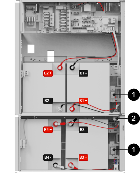
Connection of battery box
Installation of battery box, what to do in battery backup
Cable gland / knock-out is located on the underside of the battery backup and must be disconnected before mounting.
The unit must be de-energized during installation and connection.
Use the wiring that comes with the battery box to meet the wiring from the battery backup. See picture.
The picture shows cable wiring from the battery backup that meets cables from the battery box
Connection of batteries battery box
Battery wiring is mounted on the circuit board upon delivery. Pictures below only show how to connect wiring.
Warning
Damage to equipment can occur due to incorrect connection.
Note
The type of fuse between batteries varies with configuration.
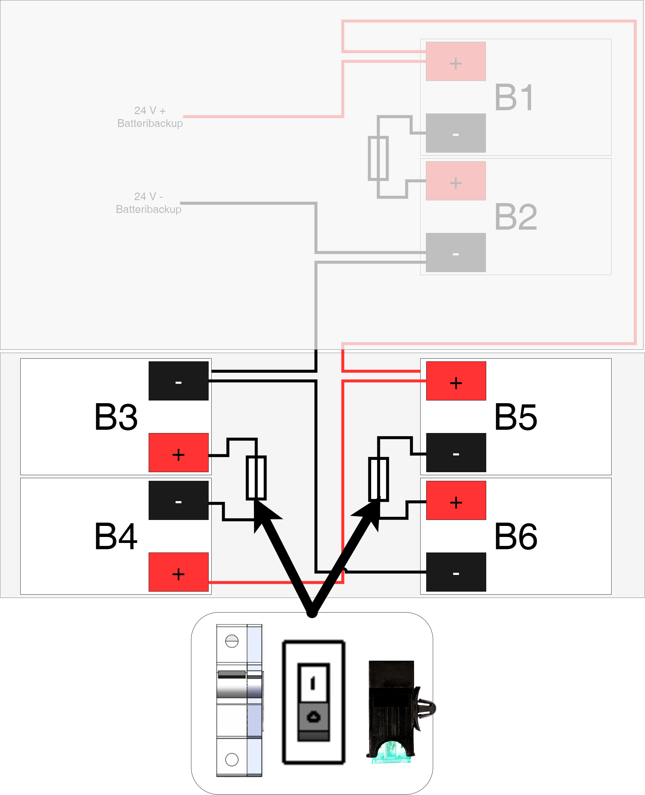
Connection to batterybox
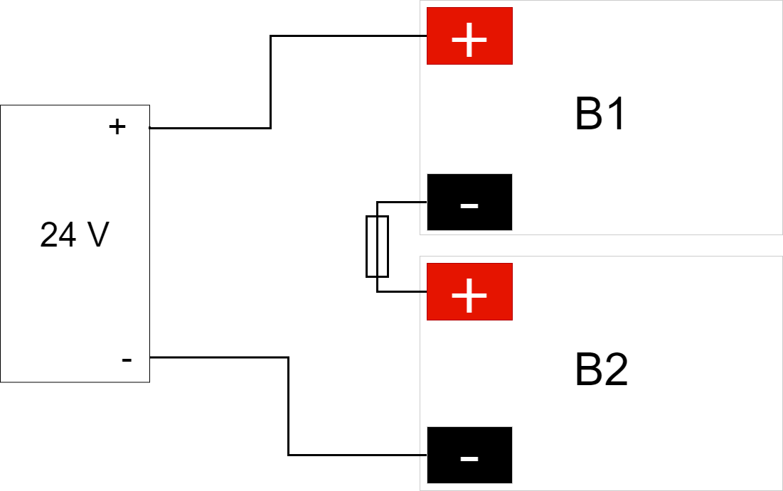
The picture also gives an overview of connection points for battery cables and battery fuses.
Battery cables | Explanation |
|---|---|
B1+ | Connects to fuse . |
B1- | Cable from motherboard is connected to battery . |
B2+ | Cable from motherboard is connected to battery . |
B2- | Connects to fuse . |
B3+ | Connects to fuse . |
B3- | Connected via connector to battery in battery backup . |
B4+ | Connected via connector to battery in battery backup . |
B4- | Connects to fuse . |
Number | Explanation |
|---|---|
1 | Battery fuse. |
2 | Connect battery backup and battery box with white square connector. |
Wiring diagram and jumper
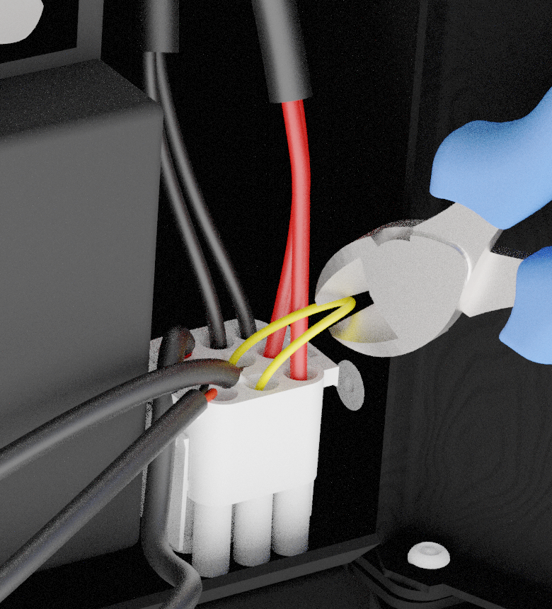
Alarms for tamper contact are connected in series and therefore the loop must be unbroken to the last battery box wiring. Jumper closes the loop on each wiring that goes from battery backup to battery box and in order for an alarm to be given on the tamper connector in the battery box, a yellow jumper on wiring must be cut. Do not cut the jumper on the last wiring in the battery box, as sabotage alarms will not be given in any connected battery backup or battery box.
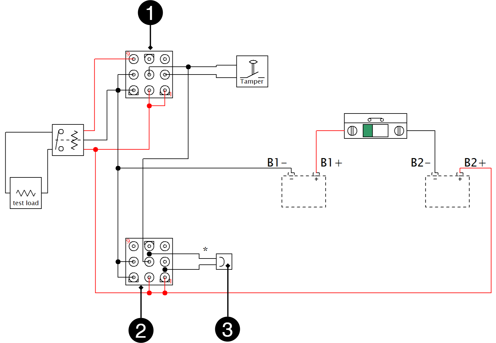
Number | Explanation |
|---|---|
1 | IN - incoming connection |
2 | OUT - outgoing connection |
3 | Jumper on base on outgoing connection |
Devices | Yellow jumper - where to cut / not cut | Where the end of the loop should be |
|---|---|---|
Battery backup without battery box | Do not cut the jumper | Jumper should remain in battery backup |
Battery backup + 1 battery box | Cut jumper from battery backup | Jumper must remain in battery box 1 |
Battery backup + 2 battery boxes | Cut jumper in battery backup and from battery box 1 | Jumper must remain in battery box 2 |
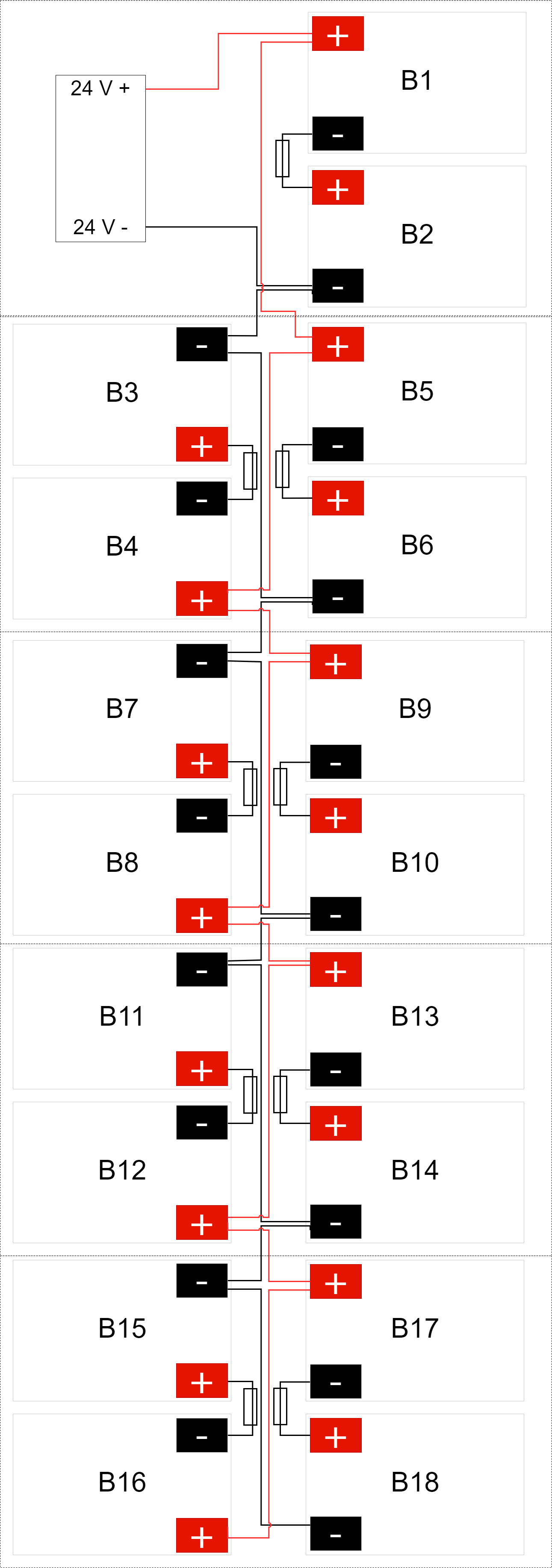
Battery backup (NOVA FLX) with 4 battery boxes (NOVA FLX)
Tamper switch when using battery box(-es)
If one or more battery boxes have been connected to the unit, the tamper switch must be connected in series in order for alarms from all units to be given. It is important that the series connection ends at the last tamper contact. The series connection must start in the battery backup unit and return to the last battery box.
All tamper contacts must be in series for everyone to be part of the alarm chain. Therefore, the yellow cable that is in the jackable connector must be cut on all connecting cables, except the last on. The cable must not be cut on the last connection / battery box.
Address and contact details
Milleteknik AB |
Ögärdesvägen 8 B |
S-433 30 Partille |
Sweden |
+46 31 340 02 30 |
info@milleteknik.se |
www.milleteknik.com |
[1] Translations in languages other than Swedish are only indicative and have not been verified. Translation must always be checked against the Swedish original to ensure correct information.