Revisions and the edition of this document
The current and most recently published edition of this document is available at www.milleteknik.com.
The validity of this document can not be guaranteed, as new editions are published without prior notice.
User manual in original language: Swedish.
Instructions for use, technical data and translations thereof may contain errors. It is always the responsibility of the installer to install the product in a safe manner.
Read this first!
Electronics, regardless of enclosure, are intended for use in a controlled indoor environment. Mains voltage should be disconnected during installation.
It is the installer's responsibility that the system is suitable for its intended use. Only authorized persons should install and maintain the system.
All information subject to change.
Instruction manual in Swedish in original[1].
Variant overview NOVA
Product name | Certified name | Motherboard: PRO1 | Motherboard PRO2: | Motherboard PRO2 v3 | Motherboard: PRO3 |
|---|---|---|---|---|---|
NOVA 12V 10A FLX S | 12 V meets the requirements but is not certified. | - | - | - | x |
NOVA 12V 10A FLX M | - | - | - | x | |
NOVA 12V 10A FLX L | - | - | - | x | |
NOVA 24V 5A FLX S | NOVA 25 50-FLX-S | X | X | - | X |
NOVA 24V 10A FLX S | NOVA 25 100-FLX-S | X | X | - | X |
NOVA 24V 5A FLX M | NOVA 25 50-FLX-M | X | X | - | X |
NOVA 24V 10A FLX M | NOVA 25 100-FLX-M | X | X | - | X |
NOVA 24V 15A FLX M | NOVA 25 150-FLX-M | X | X | X | - |
NOVA 24V 25A FLX M | NOVA 25 250-FLX-M | X | X | X | - |
NOVA 24V 5A FLX L | NOVA 25 50-FLX-L | X | X | - | X |
NOVA 24V 10A FLX L | NOVA 25 100-FLX-L | X | X | - | X |
NOVA 24V 15A FLX L | NOVA 25 150-FLX-L | X | X | X | - |
NOVA 24V 25A FLX L | NOVA 27 250-FLX-L | X | X | X | - |
Component overviewNOVA FLX L
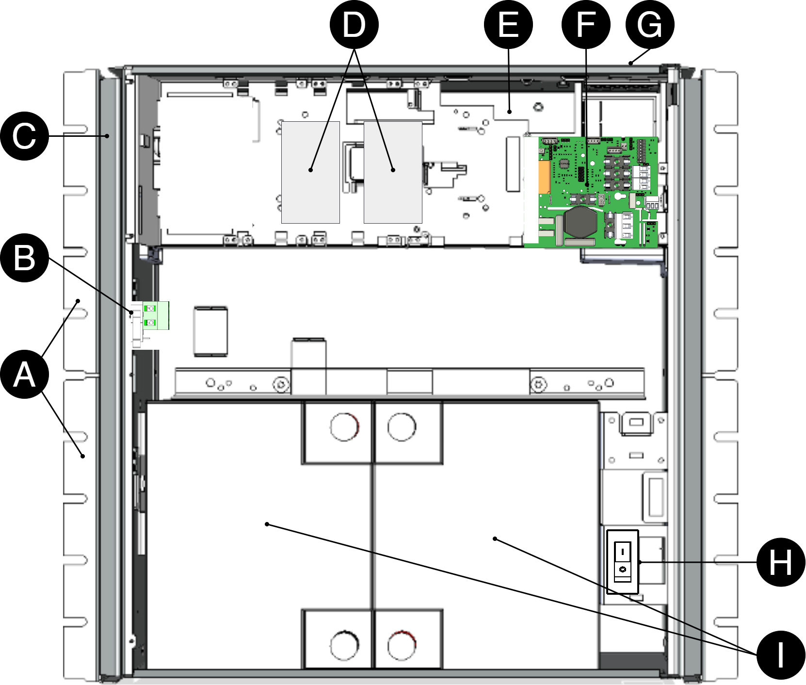
Batteries should be placed as in the picture.
Number | Explanation |
|---|---|
A | Bracket, reversible for wall mounting or 19 "rack. |
B | Sabotage contact. |
C | Cabinet in powder-coated sheet metal. |
D | Optional card slot. |
E | Power supply. |
F | Motherboard. |
G | Cable entries. |
H | Battery fuse. |
I | Space for batteries. |
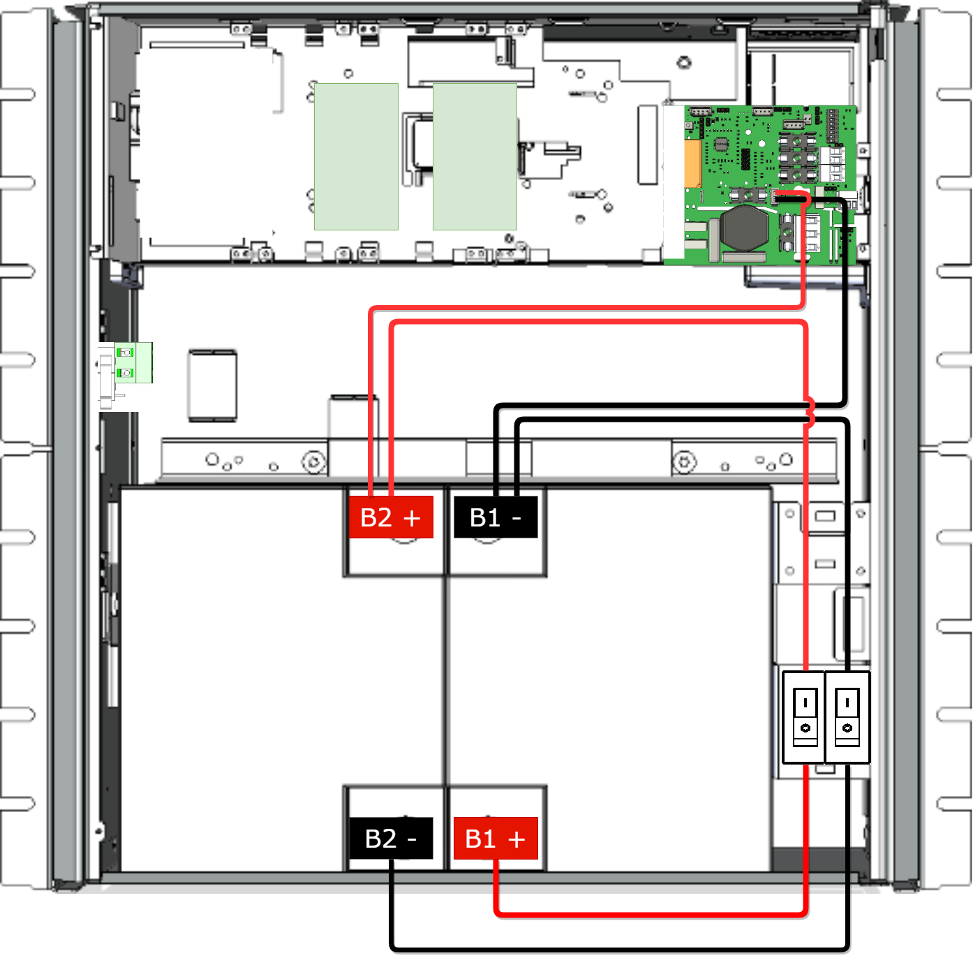
Connection of batteries, 12 V
Battery wiring is mounted on the circuit board upon delivery. Pictures below only show how to connect wiring.
Place the batteries in the cabinet with the battery terminals facing outwards, against the cabinet door.
Connect the battery cable. Red cable on plus and black cable on minus.
Disconnect the mains power (if possible) before replacing batteries.
[sv] Nr | [sv] Förklaring |
|---|---|
[sv] B1 + | [sv] Kopplas till + säkring |
[sv] B1 - | [sv] Kopplas till - säkring och moderkort. |
[sv] B2 + | [sv] Kopplas till + säkring och moderkort. |
[sv] B2 - | [sv] Kopplas till - säkring. |
PRO3 motherboard
Motherboard - description
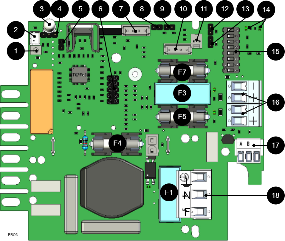
The motherboard controls the device and distributes power. See technical data for more information.
No . | On circuit board | Explanation |
|---|---|---|
1 | J24 | Power supply control. |
2 | J5 | 1=not prioritized 2=external alarm. |
3 | D9 | LED. |
4 | JU1 | For external LED in door. |
5 | J11 | Reset jumper, used when changing batteries. |
6 | JU6 | Connection for relay card or communication card or for updating firmware. Only one card or contact at a time can fit. |
7 | J29 | Connection to fan. |
8 | J101 | Connection to tamper contact. |
9 | J17 | Connection to tamper switch from battery box. |
10 | J35 | Not used. |
11 | J14 | Alarm input from external battery fuse, from battery box. |
12 and 13 | J10 and J100 | Alarm from external option card. |
14 | D18, D19 | LEDs show the status of communication (RS-485). |
15 | S3 | Dip switch |
16 | P2:1-4 | Load outputs |
17 | P3:1-3 | Communication connection, RS-485. |
18 | P1:1-3 | Connection to the mains. |
Fuses
Fuse | Type | Explanation |
|---|---|---|
F1 | T2.5A | Mains fuse |
F3 | T16A | Load fuse 1 - (for P2:2) |
F4 | T16A | Battery fuse |
F5 | T3A-T10A* | Load fuse 1+ (for P2: 1) |
F7 | T3A-T10A* | Load fuse 2 + (for P2:3) |
*The size of the fuse depends on the battery backup (rated) power outlet (A) . | ||
Warning for replacing fuses (current strength, A)
There is a risk of damage if the fuse is changed to a larger one than what the unit is delivered with. The function of the fuse is to protect the connected load and cables against damage and fire. It is not possible to change the fuse to a larger one to increase the power output.
Connect the mains to the motherboard (PCB)
Connect mains
Pull wiring through the cable entry on the cabinet.
If possible, secure the mains cable with cable ties where possible.
Electrical network cabling shall be kept separate from other cabling to avoid EMC interference.
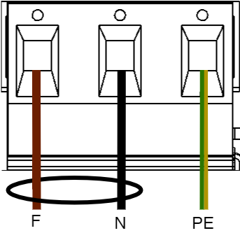
Connect the mains cable to the terminal before it is put back on the motherboard. Secure F and N with cable ties for electrical safety.
Letter | Explanation |
|---|---|
F | Phase |
N | Neutral |
PE | Protective earth |
Electrical mains connection 230 V AC on circuit board
Check that the marking on the circuit board matches the cable arrangement on the terminal block.
Connect load
Max current
The maximum current must not be exceeded. Max current is indicated on nameplate on the device.
If there are one or more connection cards (to increase the number of load outputs), load must be connected there and not on the main board.
Circuit board number | Explanation |
|---|---|
P2: 1 | Connection for load 1 + |
P2: 2 | Connection for load 1 - |
P2: 3 | Connection for load 2 + |
P2: 4 | Connection for load 2 - |
Dip switch 1-8
Dip-Switch has several different modes:
Dip switch | In mains operation or in battery operation | Comment |
|---|---|---|
1 | Address for external communication. | - |
2 | Address for external communication | - |
3 | Address for external communication | - |
4 | Address for external communication | - |
5 | Sets alarm for mains failure delay | Available from software v1.5 |
6 | Sets alarm for mains failure delay | Available from software v 1.5 |
7 | Sets alarm limit for low battery voltage in battery operation. | Available from software v 1.5 |
8 | Turns LED off or on. | Upcoming feature through software update |
8 in sequence | Performs battery test | Not available in NEO. |
Address setting for external communication (Dip switch 1-4)
Dip-Switch S1: 1-4 sets addressing.
Dip: 1 | Dip: 2 | Dip: 3 | Dip:4 | |
|---|---|---|---|---|
Adress 1 | ON | OFF | OFF | OFF |
Adress 2 | OFF | ON | OFF | OFF |
Adress 3 | ON | ON | OFF | OFF |
Adress 4 | OFF | OFF | ON | OFF |
Adress 5 | ON | OFF | ON | OFF |
Adress 6 | OFF | ON | ON | OFF |
Adress 7 | ON | ON | ON | OFF |
Adress 8 | OFF | OFF | OFF | ON |
Adress 9 | ON | OFF | OFF | ON |
Adress 10 | OFF | ON | OFF | ON |
Adress 11 | ON | ON | OFF | ON |
Adress 12 | OFF | OFF | ON | ON |
Adress 13 | ON | OFF | ON | ON |
Adress 14 | OFF | ON | ON | ON |
Adress 15 | ON | ON | ON | ON |
Mains failure delay (dip 5-6)
It is possible to change the time for when the alarm for a power outage should be given. Use the matrix to set the alarm.
Alarms for mains failure are given after: | Dip 5 | Dip 6 |
|---|---|---|
3 seconds | OFF | OFF |
30 minutes | ON | OFF |
60 minutes | OFF | ON |
240 minutes (4 hours) | ON | ON |
Low battery voltage (dip 7)
Dip: 7 has the same function regardless of whether the unit is in mains or battery operation or whether the tamper switch is held down.
Alarm for low battery voltage is given when | Dip 7 |
|---|---|
22,8 V* | ON |
24 V | OFF |
*25% of battery capacity remains. | |
LED (dip 8)
LED/battery-test always lights up when the door is open.
Dip-switch 8=ON turns off the LED.
Dip-switch 8=OFF turns on the LED.
Battery test (dip 8)
To do a battery test, dip 8 needs to change position and five seconds need to pass before the test is initiated.
If dip 8 in original position is on OFF then switch dip 8 to: ON (wait 5 seconds) and then switch back to OFF.
If dip 8 in original position is on ON then switch dip 8 to: OFF (wait 5 seconds) and then switch back to ON.
This activates the battery test after 3-8 seconds. The battery test lasts for about 6 seconds and then the LED flashes yellow quickly. Aged battery alarms may be indicated while the battery test is being performed.
Only reset dip 8 when the test is complete.
Reboot to confirm changes in address, battery and alarm settings to parent system
After the dip-switch has been set for various parameters, the device's software needs to be restarted. This is for the new settings to be stored and take effect.
Important
Rebooting according to this procedure does not interrupt the output voltage.
Restarting the device software is done by jumpering J11 (PRO3)
Important
Reboot must be done every time a change is made to the device.
NEO cannot be connected to communication/UC.
Reset after battery replacement -PRO3
After battery replacement, the device needs to measure the capacity of new batteries and clear previously set battery capacity. All alarms are cleared from the units memory, statistics remains and can not be cleared.
Insert jumper on J11 and remove jumper on J11
After doing step, the battery capacity is cleared in the units memory and is ready to read the new battery capacity.
This procedure needs to be done each time the batteries are replaced or when connecting a battery box.
Note on test of batteries
At start-up, it takes 72 hours before the system performs battery tests. This is to ensure fully charged batteries and to collect averages / history for at least 72 hours. Thereafter, every four hours, a qualified cell sample of the batteries is performed.
Note on start-up with short-circuited batteries
Peak current at start-up with short-circuited batteries: Up to 30 A p-p for 200 ms. Always follow the start-up procedure.
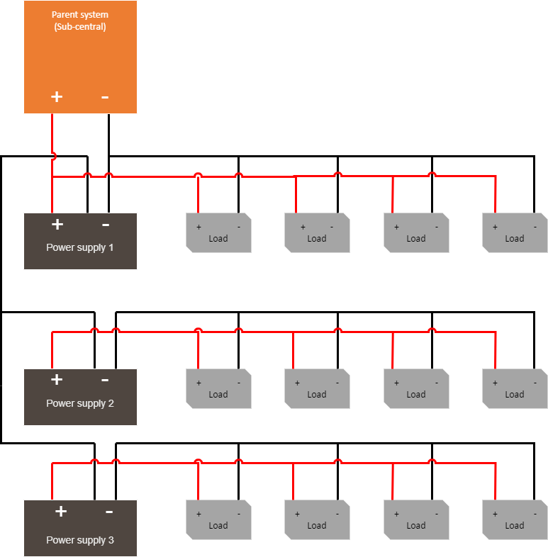
Multiple units into one parent system
To connect several units to a higher system, the load-minus between several battery backups must be connected together.
 |
Commissioning - how to start the unit
Connect batteries
Connect / switch on fuses
connect load, alarm and possibly. other connections.
Screw the mains cable into the terminal block and attach the terminal block to the motherboard.
Switch on mains voltage.
Connect in this order
To minimize the risk of errors that may occur in connection with a short circuit, connections to the motherboard must be made in this order.
The unit works normally when the indicator LED on the outside of the cabinet door lights up with a solid green light. See front panel for other status indications.
It may take up to 72 hours before the batteries are fully charged.
Alarm displayed on cabinet door
In normal mode, the indicator LED shows a solid green light.
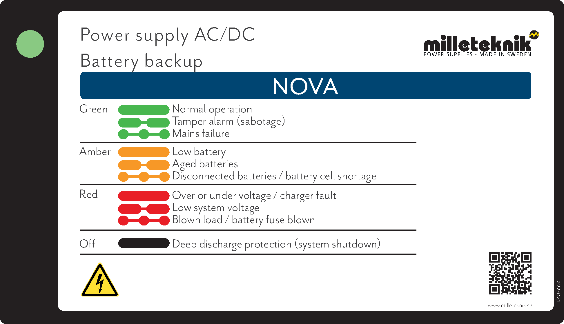 |
The indicator diode (LED) shows | Explanation |
|---|---|
Solid green light | Normal operation. |
Slow green flashes | Sabotage alarm. |
Fast green flashes | Mains failure. |
Solid yellow light | Low battery voltage. |
Slow yellow flashes | Aged batteries. |
Rapid yellow flashes | Disconnected batteries or battery cell shortage. |
Solid red light | Overvoltage or undervoltage or charger fault. |
Slow red flashes | Low system voltage. |
Rapid red flashes | Blown load or battery fuse has blown. |
No light / off | Deep discharge protection is activated. (System shutdown). |
When operating system: If the indicator LED is off, deep discharge protection has come into force.
Adjustment of tamper switch
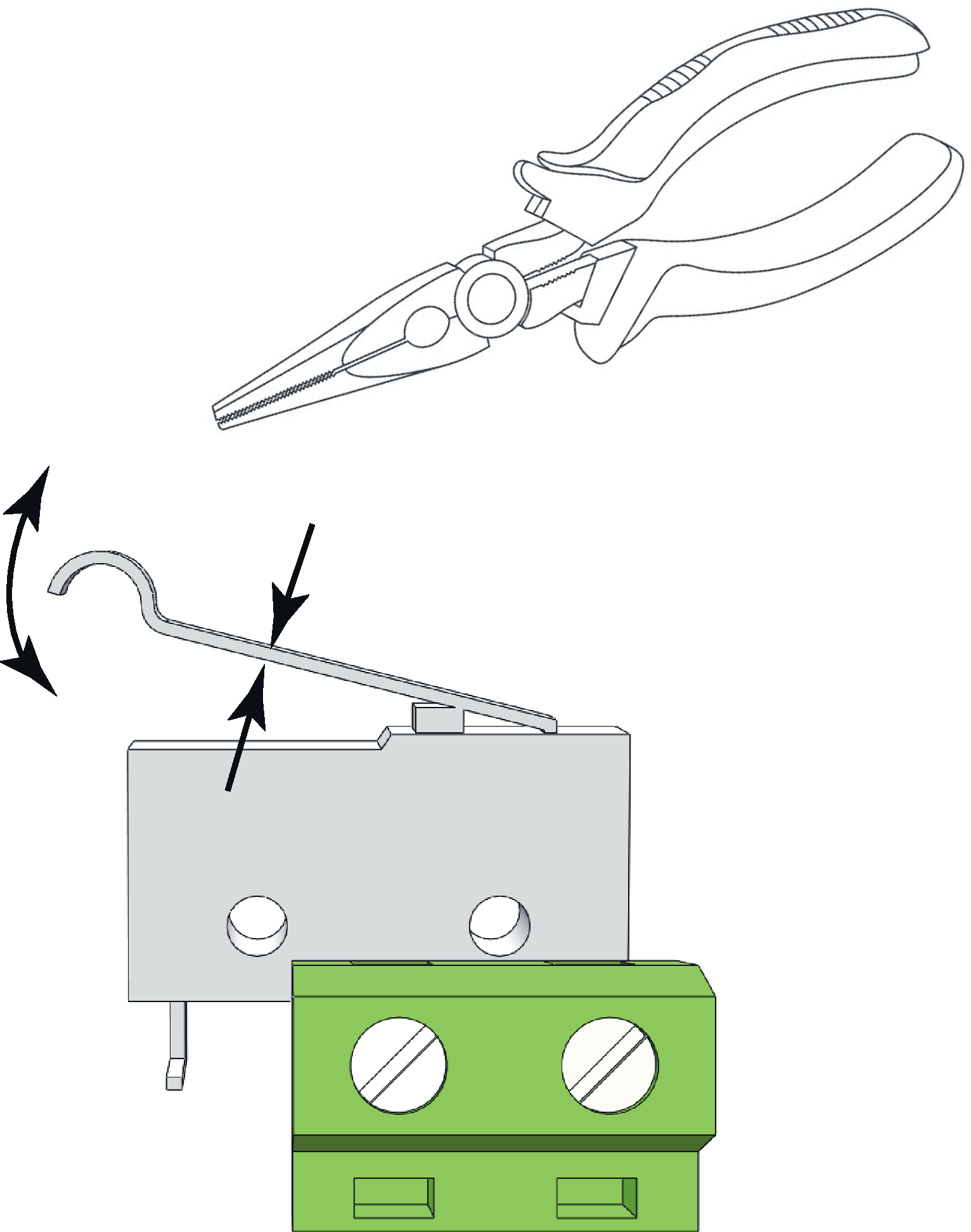 |
The tamper switch lever must be in the closed position when the cabinet door is closed. If the alarm goes off ("tamper alarm"), the lever may needs to be adjusted.
The lever is adjusted by the following steps:
Pinch with pliers in the middle of the lever.
Carefully adjust the lever in the desired direction (up / down).
Check by closing the door. A click is heard when the contact is closed.
Notice
Tamper switch will not give an alarm when closed and locked the door.
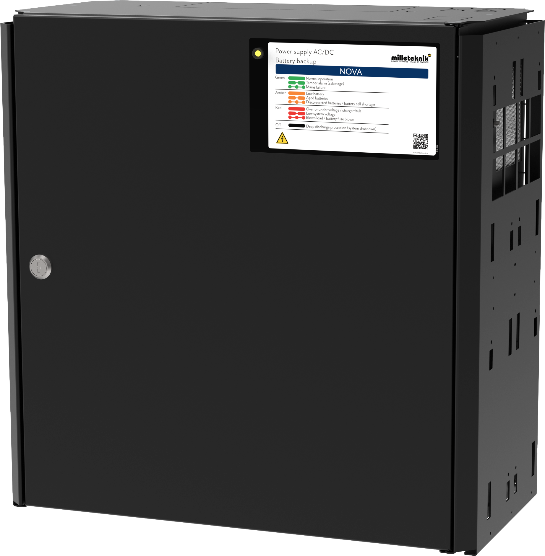
NOVA product sheet
SSF1014 certified* battery backup with communication
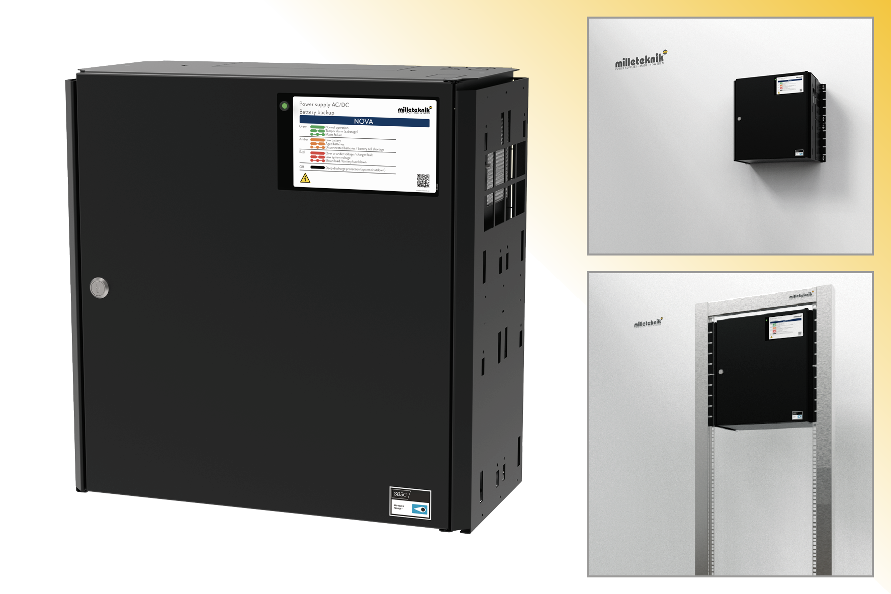 |
NOVA FLX L can be mounted on a wall or in a 19" rack.
*12 V and 24 V units are certified, with the exception of the NOVA 12V 10A FLX L which meets the requirements but is not certified.
Technical specifications
These technical specifications are subject to change without notice.
Name, article number and e-number
Name | Article number | E-number |
|---|---|---|
NOVA 12V 10A FLX L | FL01P30012P100 | 52 136 49 |
About NOVA FLX
Flexibility
NOVA FLX S can have an extra battery box. NOVA FLX M and NOVA FLX L with 1-4 extra battery boxes *. NOVA FLX M and NOVA FLX L with battery shelves in 19 ”rack *. * The battery boxes and shelves are connected via a 9-pin connector. The battery box has room for up to 2 pcs. 45 Ah batteries per battery box. Battery shelves have room for 2 pcs. 45 Ah batteries (Medium) and up to 2 pcs. 150 Ah batteries (Large) per each battery shelf.
Fixed installation
The product is intended for fixed installation. The battery backup must be installed by a qualified installer.
Area of use
NOVA FLX mostly used for: Access control system, burglar alarms, (integrated security systems), in public environments such as schools, offices and commercial properties.
Installation video

Regulations and certifications
Requirements that the product meets
EMC: | EMC Directive 2014 / 30EU |
Electricity: | Low voltage directive: 2014/35 / EU EN 62368-1 |
CE: | CE directive according to: 765/2008 |
Emission: | EN61000-6-: 2001 EN55022: 1998: -A1: 2000, A2: 2003 Klass B, EN61000-3-2: 2001 |
Immunity: | EN61000-6-2:2005, EN61000-4-2, -3, 4, -5, -6, -11 SS-EN 50 130-4:2011 Edition 2, EN50131-6 |
Emission | EN55032 (CISPR32) Class B |
Environment | REACH Regulation: Directive 1907/2006, WEEE Regulation: Directive 20021961E, RoHS Regulation: Directive 2015/863 |


Reserve operating times, power outlet and load output current
Charging current for batteries and battery capacity
The unit reads the connected system load and charges the batteries with available residual current from the power supply. The device performs qualified* battery tests and notifies when batteries need to be replaced. The batteries are charged gently to extend their life and protection is available against overcharging.
12 V / 24 V | Maximum charging current for batteries |
|---|---|
NOVA FLX L | 6 A |
The battery backup has controlled charging ** (controlled charging) which prevents batteries from being overcharged and extends their service life significantly. The NOVA series must be used with AGM batteries.
Note
NOVA 12V 10A FLX S, NOVA 12V 10A FLX M and NOVA 12V 10A FLX L meet the requirements according to EN50131-6 and SSF 1014 but have not been certified.
* Battery test is done with power resistor and the unit is tested and certified together with UPLUS 10+ Design life AGM batteries according to SSF1014. It is these batteries that must be used to maintain the certificate.
** Controlled charging means that when the batteries are fully charged, they will be disconnected electronically for standby mode for up to 20 days or when the batteries have reached 26.7 V (24 V). By discharging the batteries and charging them continuously (instead of never using them), the system extends the battery life by up to 50%. The batteries connect automatically in less than 50 microseconds.
Power outlet NOVA FLX
NOVA 12V 10A FLX L | Unit without battery box | Unit with 1 battery box | Unit with 2 battery boxes |
|---|---|---|---|
Battery | 2 st 45 Ah | - | - |
Max battery capacity | 90 Ah | - | - |
According to. SSF1014, Alarm Class 1-2 | 2.2 A | - | - |
According to. SSF1014, Alarm Class 3-4 | 0.9 A | - | - |
Imax A (max discharge current) | 10 A | - | - |
Imax b (max charging current) | 10 A | - | - |
Imin is always 0 A. | |||
Not all devices may be certified, see device certificate. | |||
About translation of this document
User manual and other documents are in the original language in Swedish. Other languages may be machine translated and/or not reviewed, errors may occur.
Circuit boards - Technical data
Technical data, motherboard: PRO 3
Info | Explanation |
|---|---|
Short name: | PRO 3 |
Product description | Motherboard in battery backup with advanced functions and communication to parent system. |
Own consumption, with relay card | Less than 100 mA. All relays retracted on external alarm card in normal mode. |
Switching time from mains voltage to battery operation | When batteries are idle: <5 microseconds. When batteries are in charge cycle: 0 (none). Batteries rest for 20-day cycles, after which a charging cycle picks up and charges the batteries for 72 hours. If there is a power failure when batteries are in the charge cycle, there is no switching time. |
Incoming electricity network | 230 V AC -240 V AC, 47-63 Hz. |
Fuse on mains | See table: Fuses. |
Indication | Indicator diode on circuit board / cabinet door |
Alarm
Alarm displayed on indicator LED on the front of the cabinet.
Cell fault in battery or unconnected battery.
Charger fault, undervoltage.
Charger fault, overvoltage.
Low system voltage, system voltage below 24.0 V in mains operation.
Low battery voltage, below 24.0 V DC in case of mains failure.
Power failure alarm.
Sabotage switch.
Fuse fault.
Aged battery
Expanding alarm functions are available via communication or with alarm cards.
Fuses | Type |
|---|---|
10 A | T10A |
Power supply fuse of 12V one | T2.5AH250V. Ceramic. |
Mains fuse for 24 V units up to 15 A | T2.5AH250V. Ceramic. |
Info | Explanation |
|---|---|
Deep discharge protection (Yes / No) | Yes. 12 V units protection at 10V, +/- 0.5 V. 24 V units protection at 20, +/- 0.5 V. |
Surge protection (Yes / No) | Yes |
Overtemperature protection (Yes / No) | Yes |
Short circuit protected = (Yes / No) | Yes |
Technical data, alarm card for PRO 3 / NEO3
Info | Explanation |
|---|---|
Card name: | PRO 3 |
Version: | 1.2 |
Product description | Motherboard in battery backup with advanced functions and communication to superior systems. |
Recommended environment | Indoors, class 1. Ambient temperature: + 5 ° C - 40 ° C. |
Protection class | IPX0 |
Recommended installation | NOVA Series (only 5 A and 10 A) |
Input voltage | 13.6 VDC, 27.3 VDC |
Self-consumption | 40 mA |
Alarm via | Alternating relay |
Number of alarm outputs | 4 pcs |
Certified according to | EN 50131-6, SBF 110: 8, SSF1014, Meets alarm class 4, SSF 1014, edition 5 |
Certificate number (SBSC) | 20-117 |
The product meets the requirements according to | CE directive according to: 765/2008, EMC Directive 2014 / 30EU, Emission: EN61000-6-: 2001, EN55022: 1998: -A1: 2000, A2: 2003 Class B, EN61000-3-2: 2001, Immunity: EN61000- 6-2: 2005, EN61000-4-2, -3, 4, -5, -6, -11. SS-EN 50 130-4: 2011 Edition 2 & SSF1014 Alarm class 1-4 (Burglar alarm). |
Producer | Milleteknik AB |
Country of origin | Sweden |
Alarm overview in alphabetical order | Relay 1 * / Alarm output 1 | Relay 2 * / Alarm output 2 | Relay 3 * / Alarm output 3 | Relay 4 * / Alarm output 4 | Communication (P5: 1-9) | Indicator LED on main card and LED on door. |
|---|---|---|---|---|---|---|
Network outages | X | - | - | - | X | X |
Fuse fault | - | X | - | - | X | X |
Sabotage switch | - | - | - | X | X | X |
Fan fault | - | - | - | - | X | - |
Charger fault, overvoltage | - | X | - | - | X | X |
Charger fault, undervoltage | - | X | - | - | X | X |
Cell fault or unconnected battery | - | X | - | - | X | X |
Low system voltage. ** | - | - | X | - | X | X |
Low battery voltage (<24.0 V DC) or power failure | - | X | - | - | X | X |
Overtemperature | - | - | - | - | X | - |
Undertemperature | - | - | - | - | X | - |
Undertemperature | - | - | - | - | X | - |
Short battery life left | - | - | - | - | X | - |
Aged battery | - | X ** | - | - | X ** | X ** |
Overcurrent 100%, minute average | - | - | - | - | X | - |
Overcurrent 80%, daily average | - | - | - | - | X | - |
Overcurrent 175%, second average | - | - | - | - | X | - |
* Alarm on potential-free relay contact. *** Not on NEO battery backups. | ||||||
RS-485 on P4: 1-4 | Explanation |
|---|---|
P4:1 | GND |
P4:2 | RX |
P4:3 | TX |
P4:4 | +5V |
Power supply
Power supply - Technical Data LRS-150-12
In: |
|---|
NOVA 12V 10A FLX L |
Info | Explanation |
|---|---|
Output voltage | 13,6 V |
Output current | 0 A - 12.5 A |
Output voltage, ripple | 150 mVp-p |
Overvoltage | 13,8 V - 16,2 V |
Voltage recharge, ripple / current limitation | Less than 0.6 Vp-p |
Efficiency | 87.5% |
Current limitation | 110% - 140% |
Constant voltage | +/- 0.5% |
Regulatory accuracy | * / - 1.0% |
Input current (230 V) | 1,7 A |
Mains voltage frequency | 47 Hz- 63 Hz |
Mains voltage | 230 V AC - 240 V AC |
Brand effect | 150 W |
Temperature range | -30°C - +70°C |
Humidity range | 20% - 90% RH non-condensed |
Technical data enclosures
Enclosures - Technical Data FLX L
Info | Explanation |
|---|---|
Name | FLX L |
Enclosure class | IP 32 |
Measure | Height: 444 mm, width 438 mm, depth 212 mm |
Height units | 10 HE |
Mounting | Wall or 19 "rack |
Ambient temperature | + 5 ° C - + 40 ° C. For best battery life: + 15 ° C to + 25 ° C. |
Environment | Environmental class 1, indoors. 20% ~ 90% relative humidity |
Material | Powder coated sheet |
Color | Black |
Cable entries, number | 4 |
Batteries that fit | 2 st 12 V 45 Ah |
Place for fan | Yes |
Link to the latest information
Products and software are subject to updates, you will always find the latest information on our website.
Warranty, support, country of manufacture and country of origin
Support
Do you need help with installation or connection?
You will find answers to many questions at: www.milleteknik.se/support
Phone: +46 31-340 02 30
Support is open: Monday-Thursday 08:00-16:00, Fridays 08:00-15:00. Closed 11:30-13:15.
Spare parts
Contacted support for questions about spare parts.
Support after the warranty period
Milleteknik provides support during the life of the product, but no longer than 10 years after the date of purchase. Replacement for an equivalent product may occur if the manufacturer deems that repair is not possible. Costs for support and replacement are added after the warranty period has expired.
Questions about product performance?
Contact sales: 46 31-340 02 30, e-mail: sales@milleteknik.se
Product life cycle, environmental impact and recycling
The product is designed and constructed for a long service life, which reduces the environmental impact. The product's service life depends on, among other things, environmental factors, mainly ambient temperature, unforeseen load on components such as lightning strikes, external damage, handling errors, and more. Products are recycled by being handed over to the nearest recycling station or sent back to the manufacturer. Contact your distributor for more information. Costs that arise in connection with recycling are not reimbursed.

Batteries - recommended, not included
Batteries are not included they are sold separately
Batteries are sold separately.
Battery combinations NOVA FLX L
Battery capacity (Ah) | Battery type | Number of batteries | Batteries in unit |
|---|---|---|---|
45 Ah | 45 Ah | 2 pcs. | 2 in Battery Backup |
90 Ah | 45 Ah | 4 pcs | 2 in Battery Backup 2 in Battery Box 1 |
155 Ah | 45 Ah | 6 pcs | 2 in Battery Backup 2 in Battery Box 1 2 and Batteribox 2 |
180 Ah | 45 Ah | 8 pcs | 0 in Battery Backup 2 in Battery Box 1 2 and Batteribox 2 2 and Batteribox 3 |
225 Ah | 45 Ah | 10 pieces. | 2 in Battery Backup 2 in Battery Box 1 2 and Batteribox 2 2 and Batteribox 3 2 and Batteribox 4 |
45 Ah, 12 V AGM battery
Fits in | Number of batteries |
|---|---|
NOVA 12V 10A FLX L | 2 |
Battery type | V | Ah |
|---|---|---|
Maintenance-free AGM, lead-acid battery. | 12 V | 45 Ah |
Article number | E-number | Article name | Terminal | Measure. Height width depth | Weight per piece | Make |
|---|---|---|---|---|---|---|
MT113-12V45-01 | 5230546 | UPLUS 12V 45Ah 10+ Design Life battery | M5 Bult | 197x165x170 mm | 14.5 kg | UPLUS |
Reserve operating times for different alarm classes - overview
The table shows the requirements for backup operating time and recharging of batteries for different alarm classes.
Important
This is a guide and all times are approximate and may differ from actual times. Load, temperature and other factors come into play, which is why exact time can not be provided.
Applies to new batteries.
Amperage and batteries vary with configuration, check if the configuration can handle batteries and amperage.
Medium current | 14 Ah 2 st 7.2 Ah batteries) | 28 Ah (2 st 14 Ah batteries) | 40 Ah (2 pcs 20 Ah batteries) |
|---|---|---|---|
Loading | Backup operating time (approx.), Minutes | ||
1 A | 485 | 970 | 1300 |
2 A | 380 | 560 | 810 |
4 A | 165 | 330 | 490 |
6 A | 120 | 245 | 360 |
8 A | 100 | 210 | 310 |
10 A | 80 | 160 | 240 |
Medium current | 90 Ah | 110 Ah | 135 Ah | 155 Ah |
|---|---|---|---|---|
- | 4 batteries (45 Ah) | 6 batteries (20 Ah + 45 Ah) | 6 batteries (45 Ah) | 8 batteries (20 Ah + 45 Ah) |
Loading | Backup operating time (approx.), Minutes | |||
0.5 A | 4705 | 5796 | 7056 | 8215 |
1 A | 2928 | 3582 | 4392 | 5070 |
2 A | 1836 | 2247 | 2754 | 3230 |
4 A | 1183 | 1438 | 1762 | 2018 |
6 A | 788 | 959 | 1175 | 1345 |
8 A | 748 | 861 | 1048 | 1150 |
10 A | 570 | 689 | 839 | 920 |
12 A | 499 | 603 | 699 | 765 |
14 A | 427 | 516 | 629 | 655 |
16 A | 404 | 499 | 592 | 590 |
18 A | 359 | 444 | 526 | 520 |
20 A | 340 | 420 | 498 | 495 |
Subject to typos.
Address and contact details
Milleteknik AB |
Ögärdesvägen 8 B |
S-433 30 Partille |
Sweden |
+46 31 340 02 30 |
info@milleteknik.se |
www.milleteknik.com |
[1] Translations in languages other than Swedish are only indicative and have not been verified. Translation must always be checked against the Swedish original to ensure correct information.