About NEO
NEO is normally used in security systems where the requirements are higher for more functions, alarm functions, longer backup operating times or when the battery backup is to handle higher loads.
About translation of this document
User manual in original language in Swedish. Other languages are machine translated and not reviewed, errors may occur.
Read this first!
If possible, leave 100 mm of free space.
The system is intended for use in a controlled indoor environment.
Only authorized persons should install and maintain the system.
It is the installer's responsibility to ensure that the system is suitable for its intended use.
Documents accompanying the system must be kept in or in its immediate vicinity.
Ventilation should not be covered. Mains voltage should be disconnected during installation.
All information subject to change.
Upon installation of this product, the installer acknowledges and accepts the limitations of this product as described in this manual.
Instructions original language: Swedish.
Component overviews
Component overview
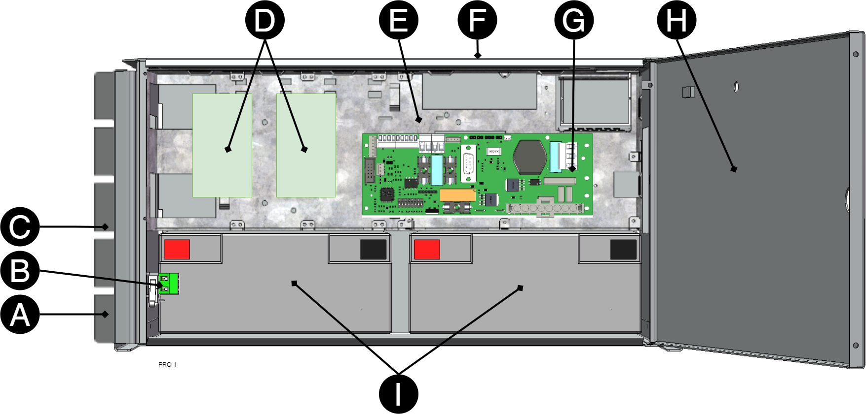
Letter | Explanation |
|---|---|
B1 +, B2 + | Bracket, reversible for wall mounting or 19 "rack. |
B | Optional: Sabotage contact |
C | Cabinet in powder-coated sheet metal. |
D | Optional card slot |
E | Power supply, sits on the back in some configurations. |
F | Cable entries. |
G | Motherboard. |
H | Lockable door. |
I | Space for batteries. |
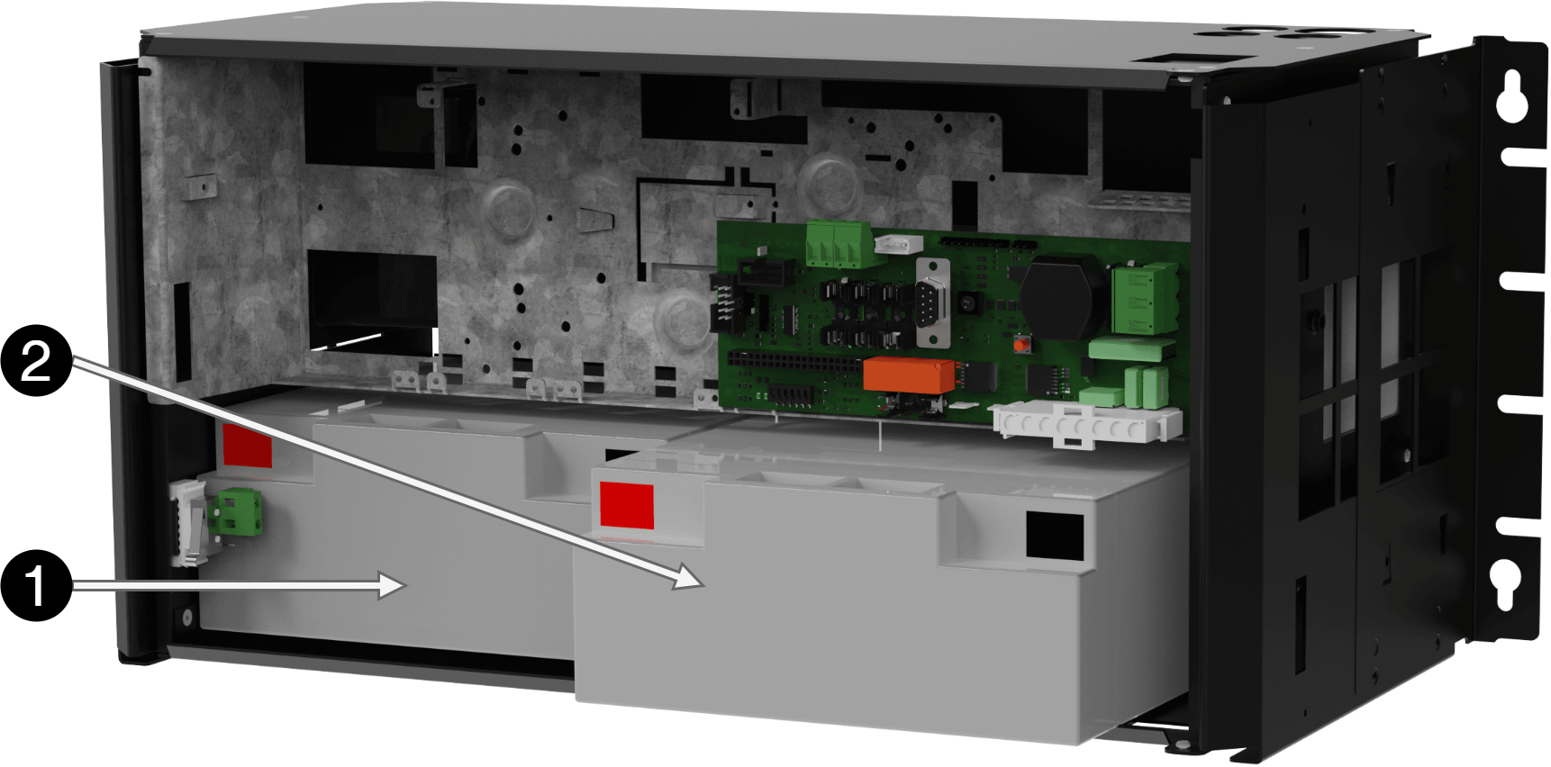
Enclosures
Bracket
Brackets are used so that the unit can be mounted on a wall or in a 19 "rack.
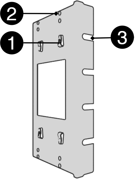
Nr | Explanation |
|---|---|
1 | Clip in bracket that secures the bracket to the housing. |
2 | Holes for screws - can be used to secure the bracket in the housing. |
3 | The brackets is screwed to a wall or 19 "rack. |
Mounting on a wall or in a 19 "rack
The unit can be mounted in a 19 ”rack or on a wall. The included brackets can be attached in two ways: When mounting on a wall, the brackets must sit backwards, against the wall. When mounting in a 19 ”rack, the console must be at the front edge of the unit.
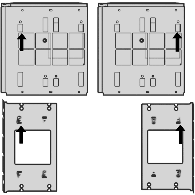
Left bracket facing the front for mounting in a 19 "rack.
Right bracket facing the back for wall mounting.
Important
Leave 100 mm free around the air vents.
Mounting
Use the appropriate screw for mounting on a wall or in a 19" rack. Screws for mounting on a wall or in a rack are not included.
Batteries - placement and connection
Placement of batteries
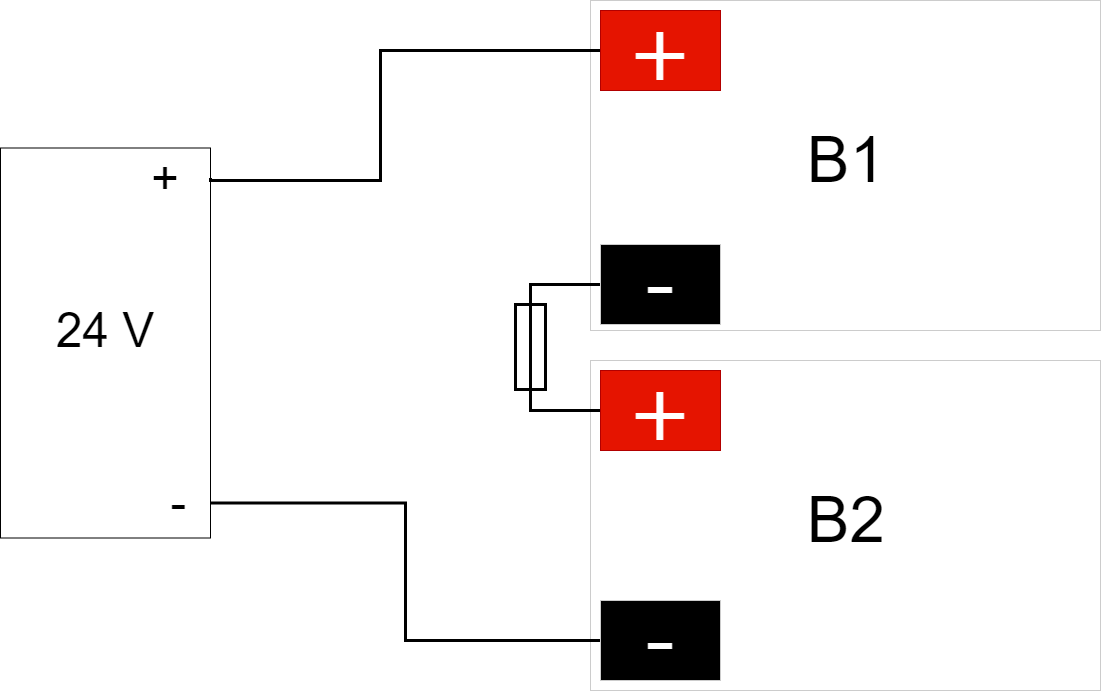
Connect battery fuse / blade fuse
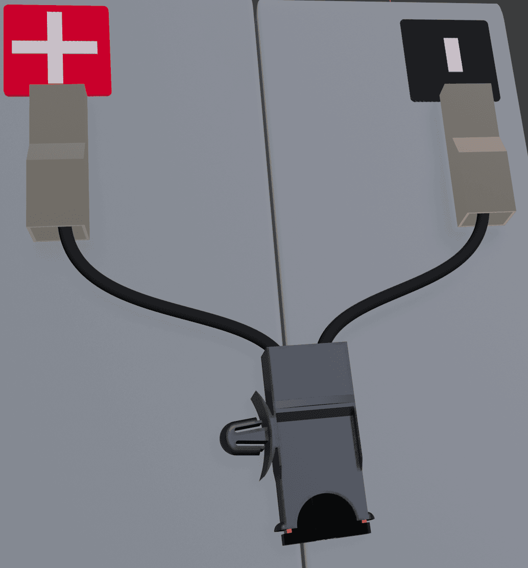
Connection of batteries in FLX S, FLX M and FLX L
Battery wiring is mounted on the circuit board upon delivery. Pictures below only show how to connect wiring.
Place the batteries in the cabinet with the battery terminals facing outwards.
Connect the battery cable. Red cable on + and black cable on -.
If possible, disconnect mains voltage when replacing the battery.
Connect the terminals correctly so that you do not damage the equipment.
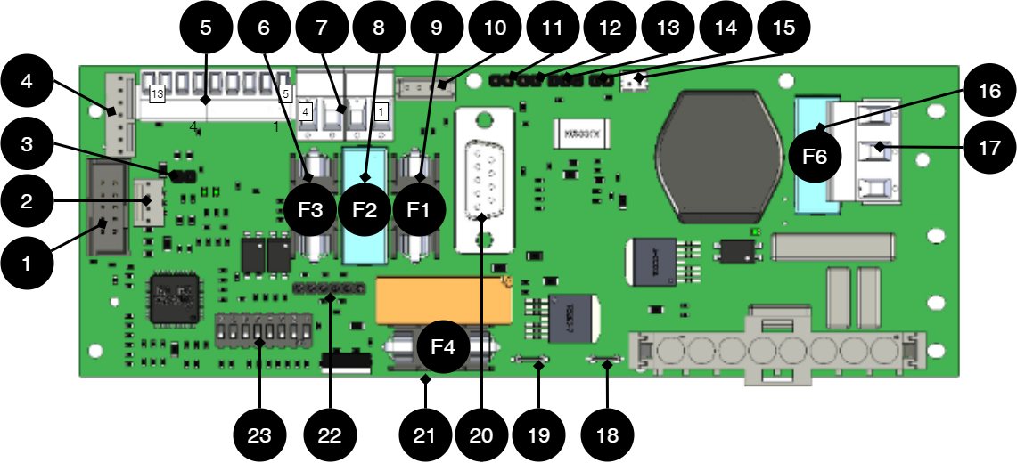
PRO1 - Moderkort
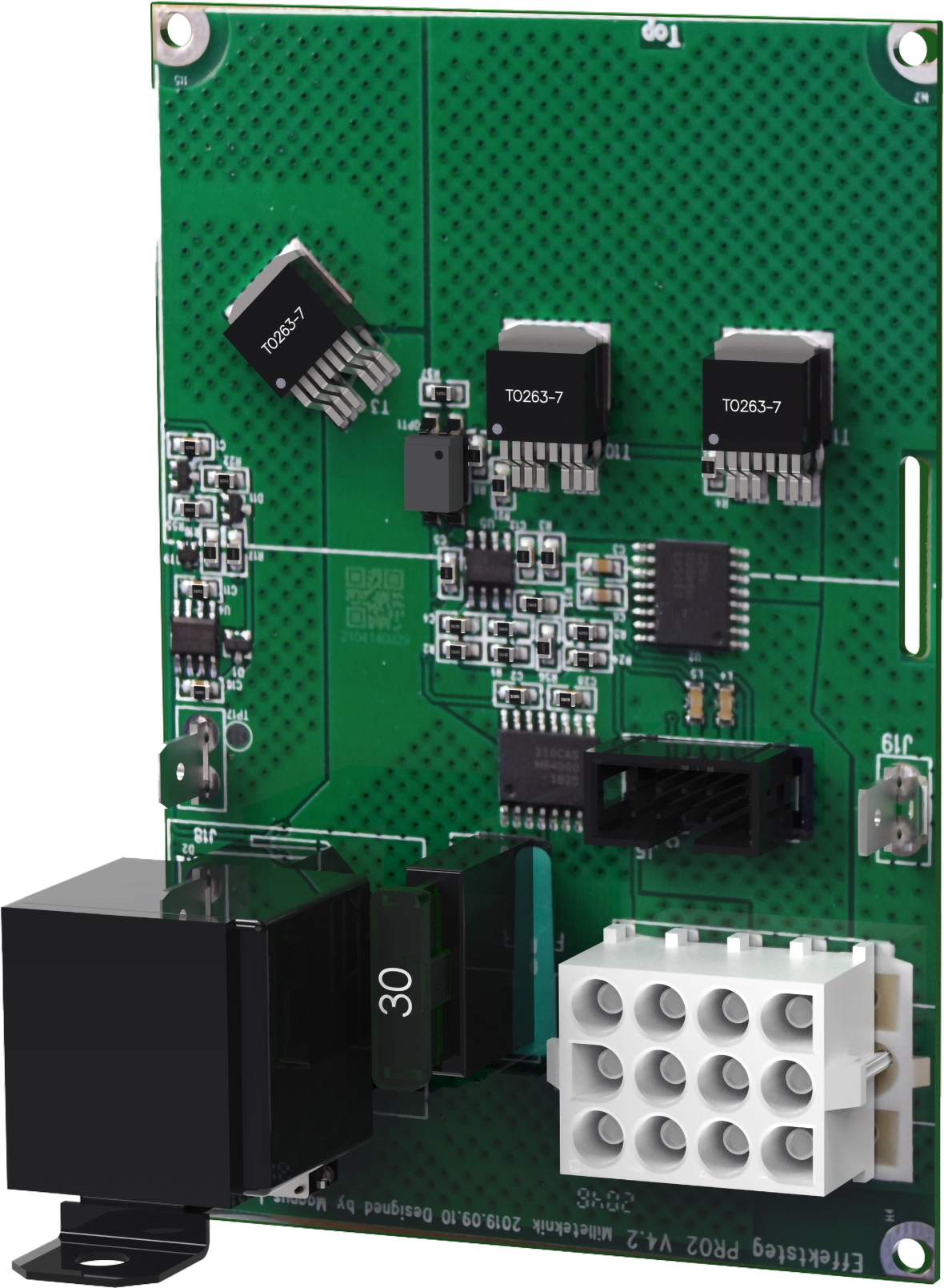
Motherboard - description
Motherboard controls the device, distributes power and communicates with other systems. See technical data for more information.
No . | On circuit board | Explanation |
|---|---|---|
1 | PGM1 | Port for firmware update. |
2 | J12 | Connection indicator diode. |
3 | J5 | Termination by jumper, (at over 120 Ω, RS-485). |
4 | J9 | Effect card connection. |
5 | P2:5-13 | Connection for communication. |
6 | F3 | Fuse, load 2 +. (5A and 10A units.) |
7 | P2:1-4 | Load outputs for 5 A and 10 A units only. |
8 | F2 | Fuse, load 1 -. (5A and 10A units.) |
9 | F1 | Fuse, load 1+. (5A and 10A units.) |
10 | J2 | Connection to fan. |
11 | J11 | Tamper switch connection. |
12 | J7 | Connection tamper switch from battery box. |
13 | JU2 | Input from external fuse card, NO. |
14 | J15 | Input from external fuse card, NC. |
15 | J13 | Connection to external alarm. Optional card. |
16 | F6 | See fuses. |
17 | P1:1-3 | Incoming mains, (230 V). Line, Phase, PE. |
18 | J16 | Power resistor connection. |
19 | J4 | Power resistor connection. |
20 | D-sub | Connection option card via D-sub. |
21 | F4 | Battery fuse. |
22 | J8 | Connection to relay/communication card. |
23 | S1 | Dip switch 1-8 |
Fuses
Fuses | Type | Explanation |
|---|---|---|
F1 | See table: fuses | Fuse, load 1 plus +. |
F2 | Fuse, load 1 minus -. | |
F3 | Fuse, load 2 plus +. | |
F4 | Battery fuse. | |
F6 | Mains fuse. |
Fuse Replacement Warning (A)
There is a risk of damage if the fuse is changed to a larger one than what the unit is delivered with. The function of the fuse is to protect the connected load and cables against damage and fire. It is not possible to change the fuse to a larger one to increase the power output.
Fuse | Type |
|---|---|
10 A | T10A |
15 A | T15A |
25 A | T25A |
Mains fuse for 24 V units up to 15 A | T2.5AH250V. Ceramic. |
Mains fuse for 24 v units over to 15 A | T4AH250V. Ceramic. |
Connect the mains to the motherboard (PCB)
Connect mains
Pull wiring through the cable entry on the cabinet.
If possible, secure the mains cable with cable ties where possible.
Electrical network cabling shall be kept separate from other cabling to avoid EMC interference.
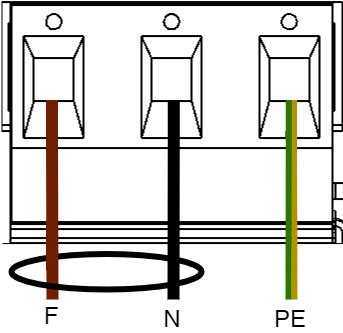
Connect the mains cable to the terminal before it is put back on the motherboard. Secure F and N with cable ties for electrical safety.
Letter | Explanation |
|---|---|
F | Phase |
N | Neutral |
PE | Protective earth |
Electrical mains connection 230 V AC on circuit board
Check that the marking on the circuit board matches the cable arrangement on the terminal block.
Connect load
Max current
The maximum current must not be exceeded. Max current is indicated on nameplate on the device.
If there are one or more connection cards (to increase the number of load outputs), load must be connected there and not on the main board.
Circuit board number | Explanation |
|---|---|
P2: 1 | Connection for load 1 + |
P2: 2 | Connection for load 1 - |
P2: 3 | Connection for load 2 + |
P2: 4 | Connection for load 2 - |
Connection of load 15 A - 25 A units
For units with a effect card, which is available to handle the higher currents (15 ampere and above), the load must be connected on an optional board.
See documentation for option board for how to connect load.
Warning
Load must not be connected to the motherboard if the device is a 15 A or 25 A, as it will be destroyed during commissioning. Motherboards that are faulty due to incorrect connections are not covered by warranty.
The effect card increases the current for 15 A and 25 A units.
Dip-switch - S1
The contact on the dip switch has two positions, ON and OFF.
Dip-switch S1 | Explanation |
|---|---|
5 | Sets the fan speed. |
5-7 | Battery capacity setting. |
8 | For software reset. |
Note
NEO cannot be connected to communication/UC.
Reboot to confirm changes in address, battery and alarm settings to parent system
After the dip-switch has been set for various parameters, the device's software needs to be restarted. This is for the new settings to be stored and take effect.
Important
Rebooting according to this procedure does not interrupt the output voltage.
Restarting the device software is done by turning Dip-switch 8: OFF-ON-OFF (PRO1)
Important
Reboot must be done every time a change is made to the device.
NEO cannot be connected to communication/UC.
Fan speed - setting, Dip-switch 5
Dip-Switch 5 sets the fan speed. (As of software V 4.27.)
Dip-5 | Mode | Temperature limit | Benifit | Drawback |
|---|---|---|---|---|
OFF | Normal mode (factory setting). | High speed above 30°C, restores normal mode when the temperature is 25°C. | Best for battery life. | Louder noise from the fan. |
ON | Office environment mode. | High speed at 35°C, restores normal mode when the temperature is 30°C. | Lower noise level. | Shortens the lifespan of the batteries. |
Battery capacity setting, Dip switch 5-7
The device is set for the battery capacity that the product can handle the most (largest batteries). If other batteries are to be installed, the battery capacity setting needs to be changed so that alarms and functions works as intended.
Setting the new battery capacity is done by keeping the tamper switch pressed while Dip-switch 5-7 is changed and the unit is commissioned.
Open the device and let it operate normally.
Press the tamper switch on the door frame. The device is now in write mode for battery capacity setting.
Set the connected battery capacity on the Dip switch, according to the table.
Release the tamper switch in the door frame. Battery capacity is now stored.
Batteries | Dip 5 | Dip 6 | Dip 7 |
|---|---|---|---|
7,2 Ah | OFF | OFF | OFF |
14 Ah | ON | OFF | OFF |
20 Ah | OFF | ON | OFF |
28 Ah | ON | ON | OFF |
45 Ah | OFF | OFF | ON |
60 Ah | ON | OFF | ON |
90 Ah | OFF | ON | ON |
120 Ah and above | ON | ON | ON |
Resetting data after battery change (Dip-switch 8)
In order for the system to measure the capacity of new batteries, the unit needs to clean up previous battery capacity. Dip-switch 8 makes a software set that, among other things, resets alarms.
Important
The action clears the memory on the card immediately.
Dip-switch 8 must be switched to: OFF-ON-OFF
Alarm card for PRO1
Relay card - description, connections and alarm outputs.
All fault alarm relays must be in the drawn state. Make sure the connection between CO and NC is at closure. Put the measuring instrument on continuity measurement and test closure. This should then indicate a short circuit.
All relay outputs are normally live and give an alarm in the event of no voltage.
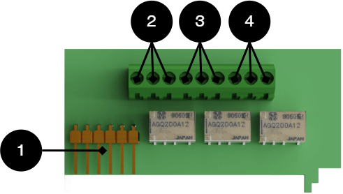 |
No . | Relay (Terminal no.) | The relay is normally energized. | Alarm type or explanation |
|---|---|---|---|
1 | J12 | - | Connection to motherboard. |
2 | J14:1-3 | NC, COM, NC | Power outage alarm. |
3 | J14:4-6 | NC, COM, NO | Alarm for: Fuse failure, tamper switch*, charger failure overvoltage, charger failure undervoltage, cell failure/battery not connected, low battery voltage in case of mains failure and aged battery*. |
4 | J14:7-9 | NO, COM, NC | Alarm for: Low system voltage. |
Via communication on PRO1 card: All alarms and alarms for: Fan fault, overtemperature, subtemperature, short battery life left, overcurrent 100% of minute average, overcurrent 80% daily average and overcurrent 175% second average. * Optional on units that are not certified. | |||
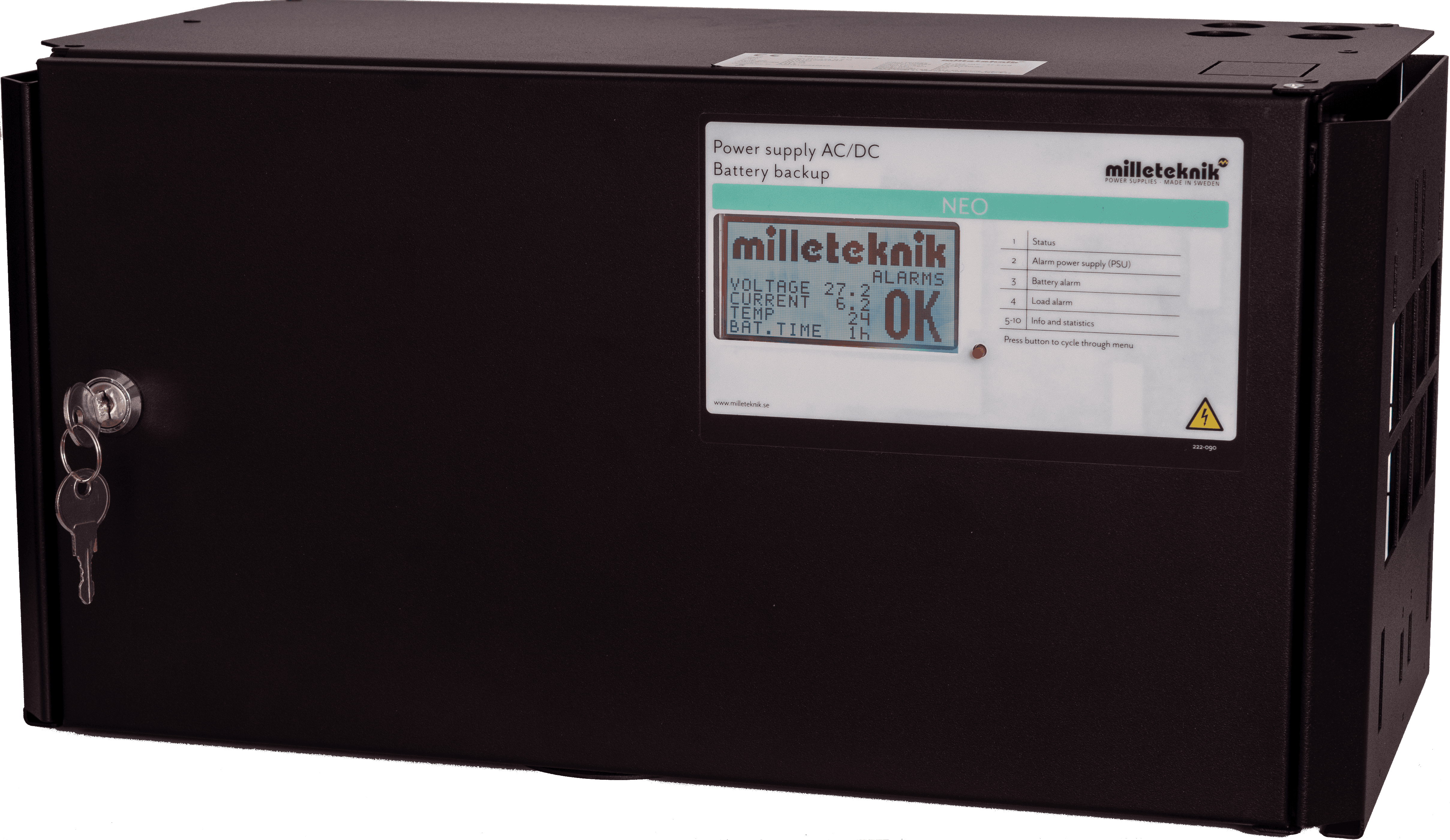
NEO display
Display on cabinet door
On NEO with display, battery capacity can be set and alarms and battery backup status can be displayed. By pressing the button, the battery capacity can be set and the status can be read. Press the button to scroll between the pages on the screen.
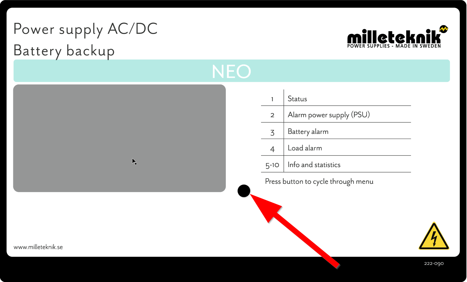
The push button scrolls between the screens and is used to set the battery capacity.
Language on display

The language shown on the display is English.
It is not possible to change the language.
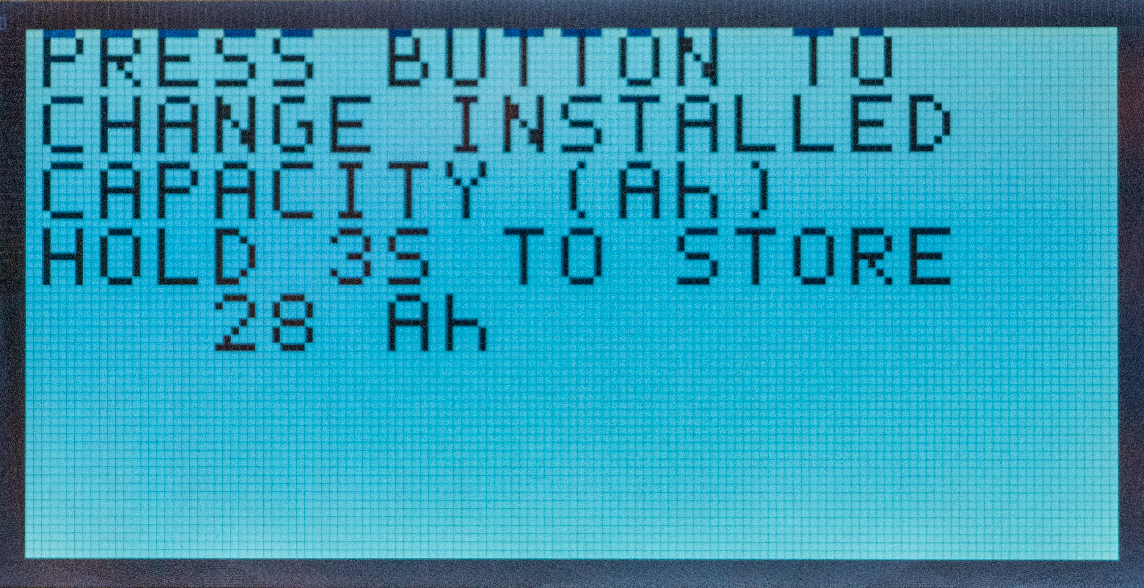
Settings screen (page 1/10)
When the device is turned on, the settings screen will first appear. Battery capacity is set here. Press the button until the same battery installed appears. Then press and hold the button for 3 seconds to save the change.
The settings screen is in English.
On display | Translation / |
|---|---|
PRESS BUTTON TO CHANGE THE INSTALLED CAPACITY (Ah) | Hold the button to change the installed (battery) capacity (Ah). |
HOLD 3S to STORE | Hold the button for 3 seconds to store value. |
28 Ah | 28 Ah / By holding down the button, the value for the set battery will change. |
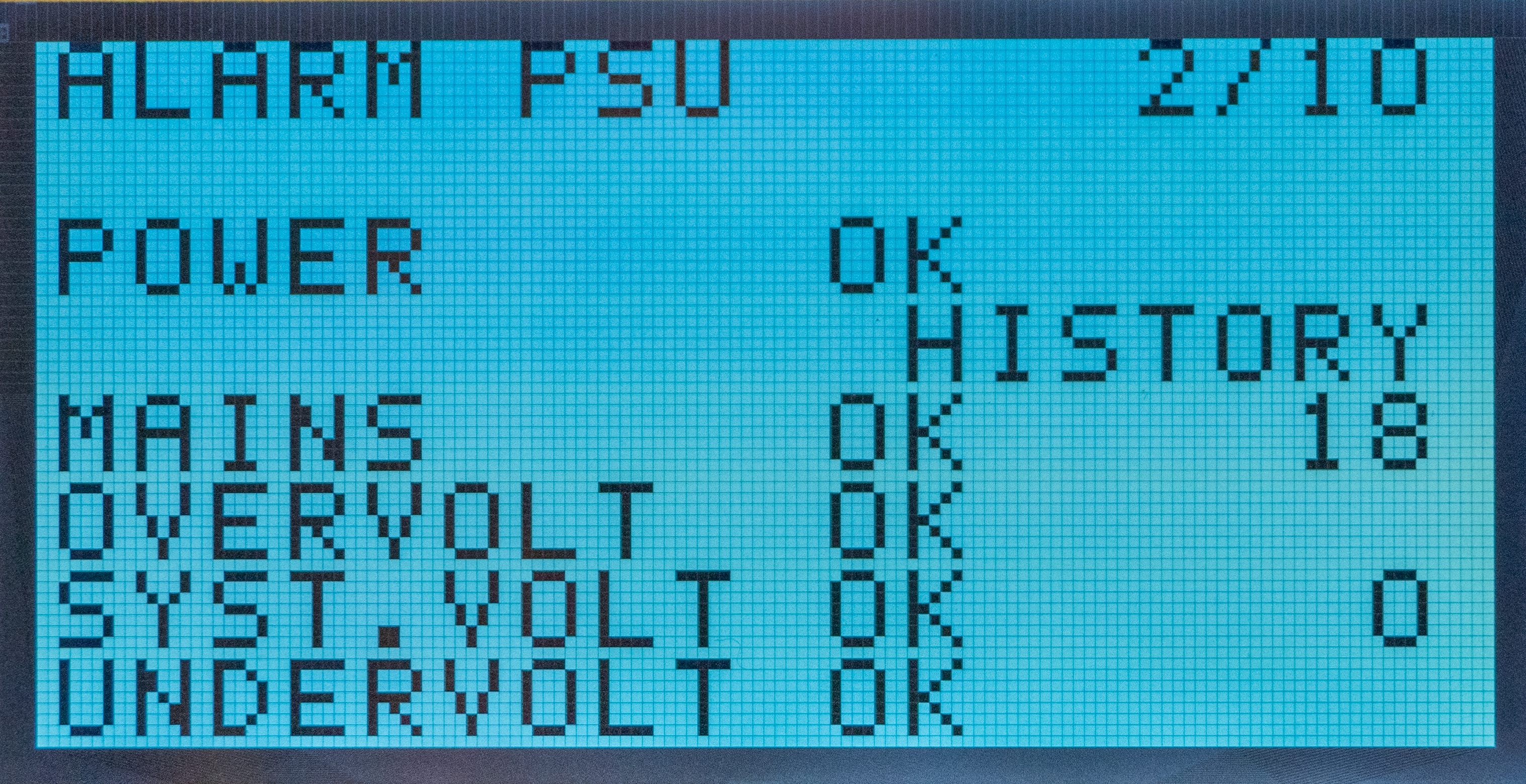
Alarm from the battery backup power supply (page 2/10)
Name on display | Status on display | Translation | Explanation |
|---|---|---|---|
ALARM PSU 2/10 | - | Alarm from power supply | 2/10 is page 2 of 10 shown on the display |
POWER | OK | Power | Overall power supply status. |
HISTORY | 18 | History | Number of alarms since the device was started. |
MAIN | OK | Mains voltage | 230 V mains voltage. |
OVERVOLT | OK | Overvoltage | Number of alarms since the device was started. |
SYS. VOLT | OK/0 | System voltage | Number of alarms since the device was started. |
UNDERVOLT | OK | Undervoltage | Number of alarms since the device was started. |
OK=OK FAIL=Error | |||
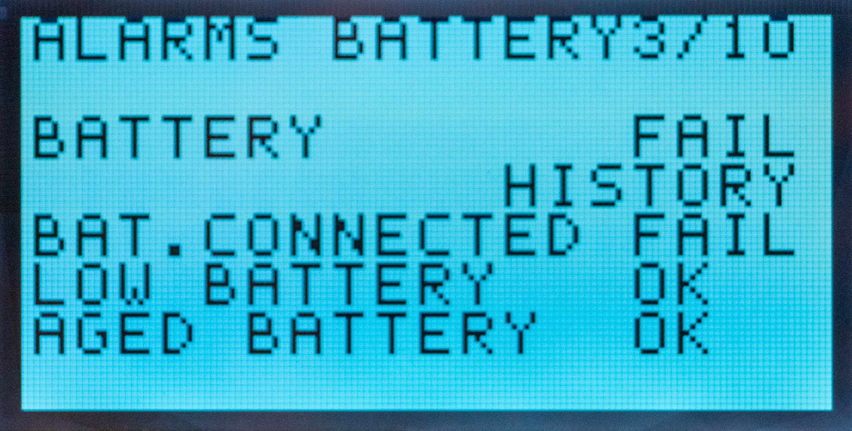
Alarm from batteries (page 3/10)
Name on display | Status on display | Translation | Explanation |
|---|---|---|---|
ALARMS BATTERY | - | Alarm from batteries | 3/10 is page 3 of 10 shown on the display |
BATTERY | OK/FAIL | Battery | Overall battery status |
HISTORY | - | History | Shows the number of alarms since the battery backup was first started. |
BAT.CONNECTED | OK/FAIL | Battery connected | Shows if battery is connected. |
LOW BATTERY | OK/FAIL | Low battery voltage | Gives an alarm when the battery voltage drops below XXX in mains operation. This alarm does not appear when the unit is running on battery power. |
AGED BATTERY | OK/FAIL | Aged battery | Battery age status. |
OK=Ok FAIL=Error | |||
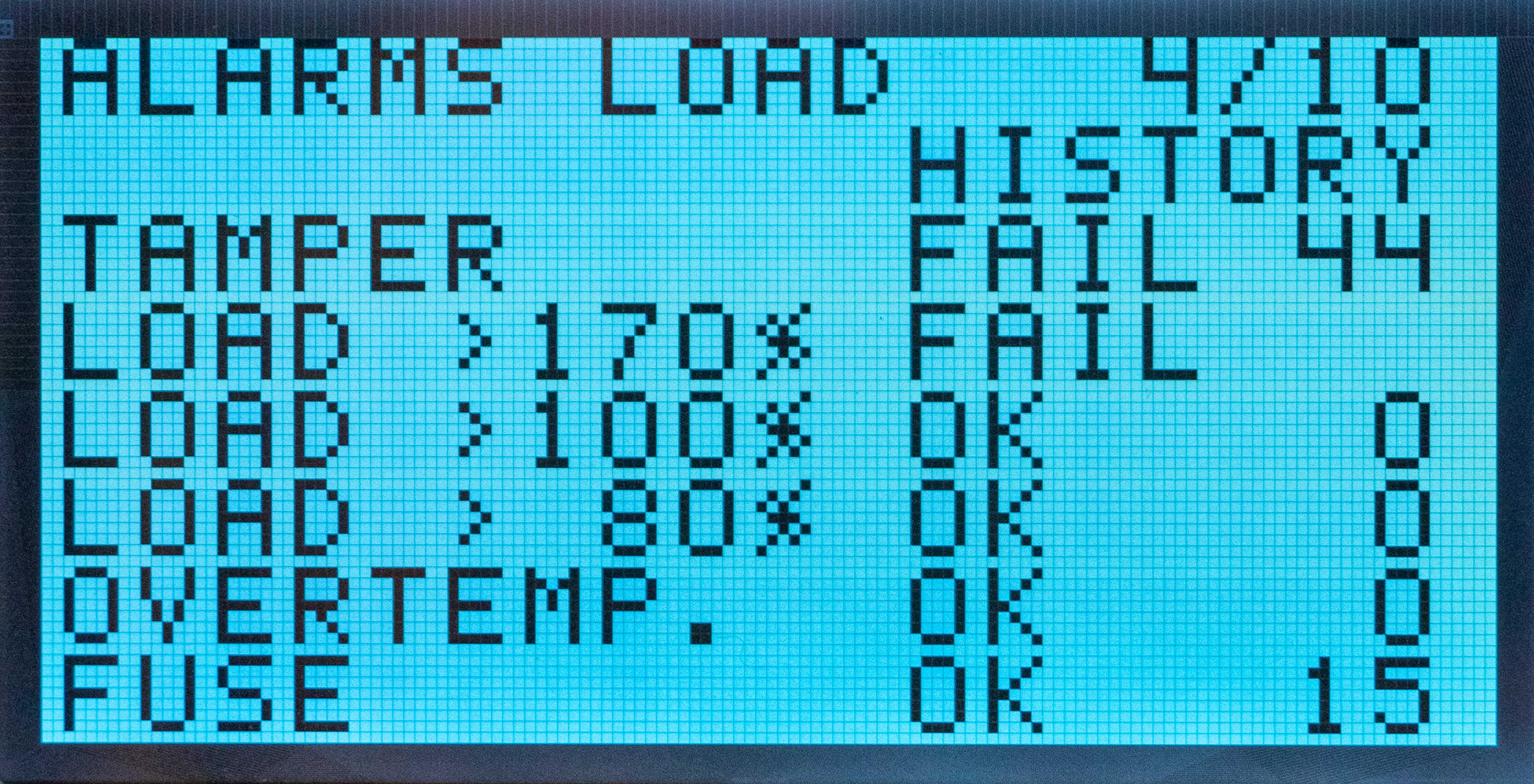
Alarm from tamper contact, load, temperature and fuse (page 4/10)
Name on display | Status on display | Number on display | Translation | Explanation |
|---|---|---|---|---|
ALARMS LOAD | - | 4/10 | Alarm load | 4/10 is page 4 of 10 shown on the display |
HISTORY | - | 44 | History | Number shows the number of errors (44 times in the image example) that have occurred in the battery backup since start. |
TAMPER | OK/FAIL | 0 | Battery connected | Shows if battery is connected. |
LOAD >170% | OK/FAIL | 0 | Load above 170% | Numbers show the number of times the load has exceeded the limit value. |
LOAD >100% | OK/FAIL | 0 | Load over 100% | Numbers show the number of times the load has exceeded the limit value. |
LOAD >80% | OK/FAIL | 0 | Load over 80% | Numbers show the number of times the load has exceeded the limit value. |
OVERTEMP. | OK/FAIL | 0 | Over temperature | Temperature alarm for the device. Numbers show the number of times the load has exceeded the limit value. |
FUSE | OK/FAIL | 15 | Fuse | Number shows the number of times the fuse has tripped. (15 times in the image example) |
OK=Ok FAIL=Error | ||||
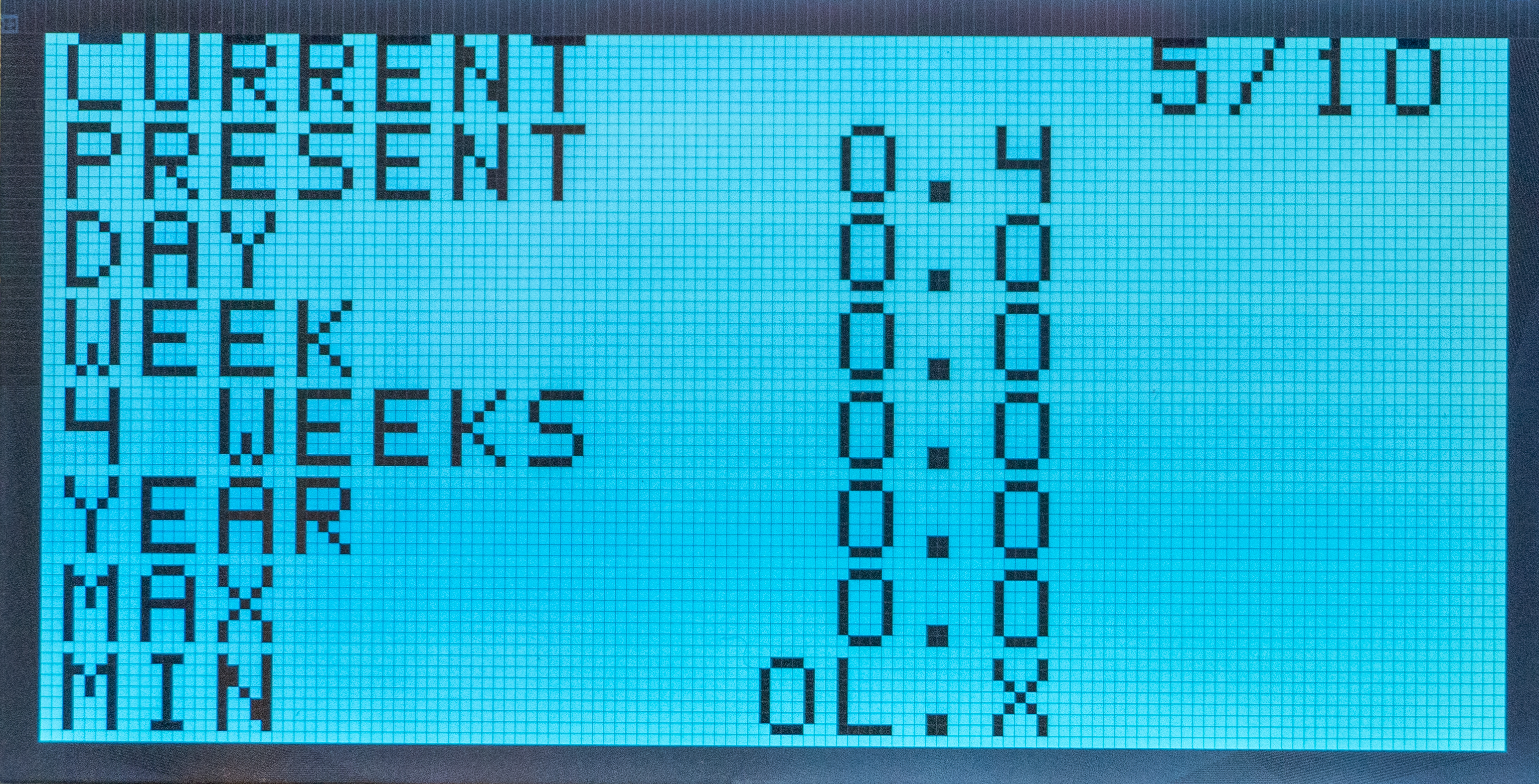
Current measurement (page 5/10)
Name on display | Number on display | Translation | Explanation |
|---|---|---|---|
CURRENT | 5/10 | Current | 5/10 is page 5 of 10 shown on the display |
GIFT | 0,4 | Current | Shows the device's current current measurement in real time. |
DAY | 0 | Day | Shows the device's power consumption for the last 24 hours, (avg |
WEEK | 0 | Week | Shows the device's power consumption for the last seven days, (average value). |
4 WEEKS | 0 | Four weeks | Shows the device's power consumption for the last 30 days, (average value). |
YEAR | 0 | Year | Shows the device's power consumption for the last 365 days, (average value). |
MAX | 0 | Max | Shows the maximum current the device has had since it was put into operation. |
MY | 0L.X | My | Shows the minimum power the device has had since it was put into operation. |
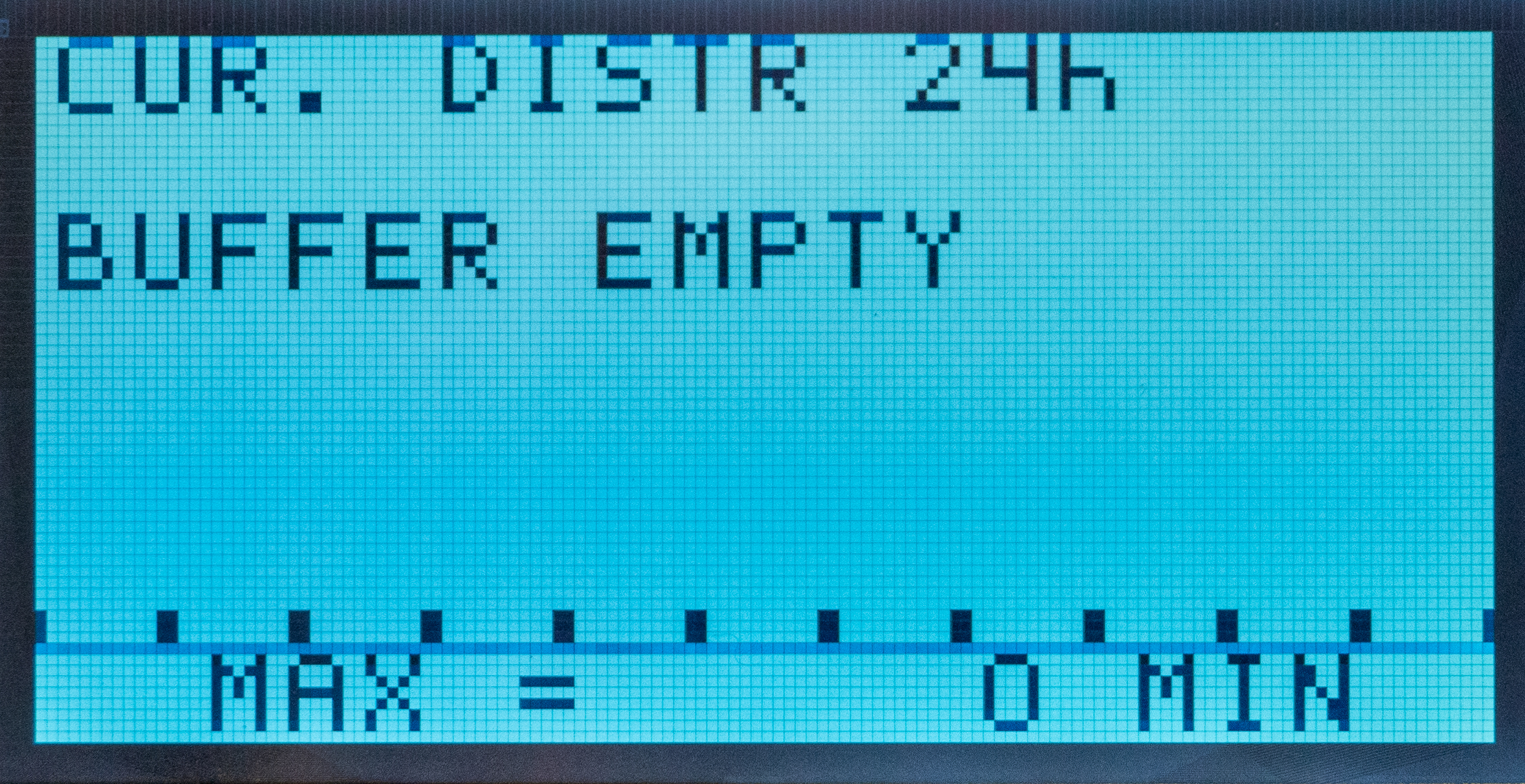
Current measurement - graph (page 6/10)
Name on display | Number on display | Translation | Explanation |
|---|---|---|---|
CUR. DIST | 24h | Current | Displays current measurement (in a graph) for the last 24 hours. |
BUFFER EMPTY | XX/Empty | Buffer | Shows how long the device can be operated in battery mode with the current load. |
MAX= | 0 MIN | Max= | Indicates the number of minutes the device can be operated on batteries, (with current load). |
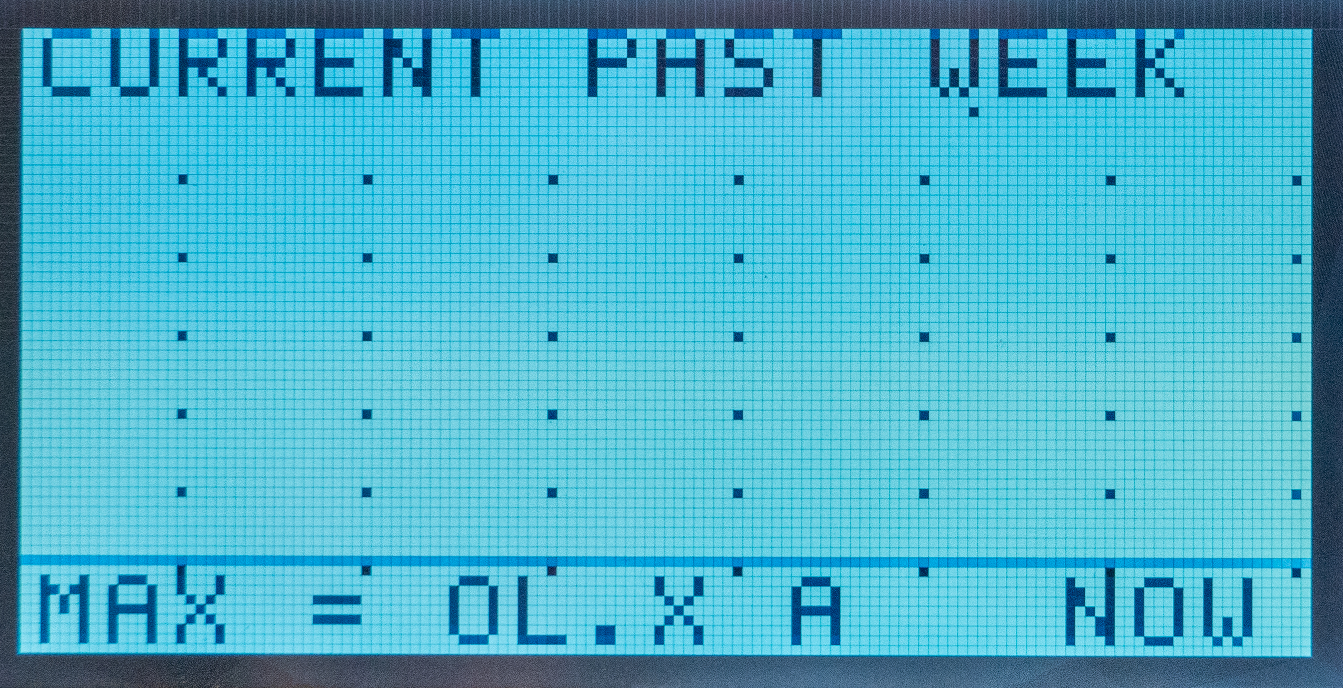
Current measurement - weekly graph (page 7/10)
Note
This is inactive and not in use.
Display will not show anything.
Name on display | Number on display | Translation | Explanation |
|---|---|---|---|
CURRENT PAST WEEK | - | Current last week | Shows current measurement (in a graph) for the last 7 days. |
MAX= | 0 MIN | Max= | Indicates the number of minutes the device can be operated on batteries, (with current load). |
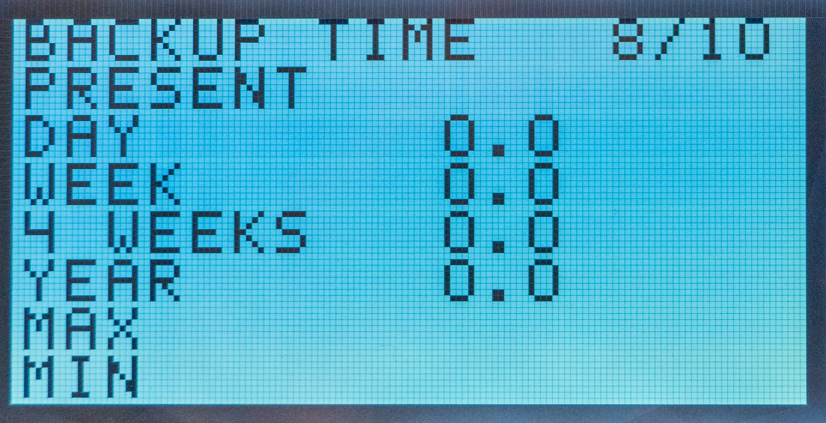
Standby time (page 8/10)
Name on display | Number on display | Translation | Explanation |
|---|---|---|---|
BACKUP TIME | 8/10 | Current | 8/10 is page 8 of 10 shown on the display |
GIFT | 0 | Current | Displays the device's current reserve drive time in real time. |
DAY | 0 | Day | Shows the device's current standby time for the last 24 hours, (average value). |
WEEK | 0 | Week | Shows the device's current standby time for the last seven days, (average value). |
4 WEEKS | 0 | Four weeks | Shows the device's current standby time for the last 30 days, (average value). |
YEAR | 0 | Year | Shows the device's current standby time for the last 365 days, (average value). |
MAX | 0 | Max | Shows the highest reserve operating time the device has had since it was put into service. |
MY | 0L.X | My | Shows the minimum spare operating time the device has had since it was put into service. |
Voltage (page 9/10)
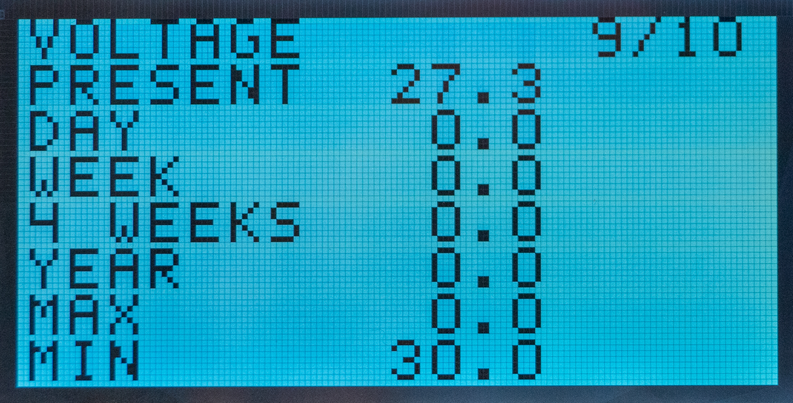
Name on display | Number on display | Translation | Explanation |
|---|---|---|---|
VOLTAGE | 9/10 | Volt | 9/10 is page 9 of 10 shown on the display |
GIFT | 27,3 | Current | Displays the device's current current voltage in real time. |
DAY | 0 | Day | Shows the voltage of the device for the last 24 hours, (average value). |
WEEK | 0 | Week | Shows the voltage of the device for the last seven days, (average value). |
4 WEEKS | 0 | Four weeks | Shows the voltage of the device for the last 30 days, (average value). |
YEAR | 0 | Year | Shows the voltage of the device for the last 365 days, (average value). |
MAX | 0 | Max | Shows the highest voltage the device has had since it was put into operation. |
MY | 30.0 | My | Shows the minimum voltage the device has had since it was put into operation. |
Voltage (page 10/10)
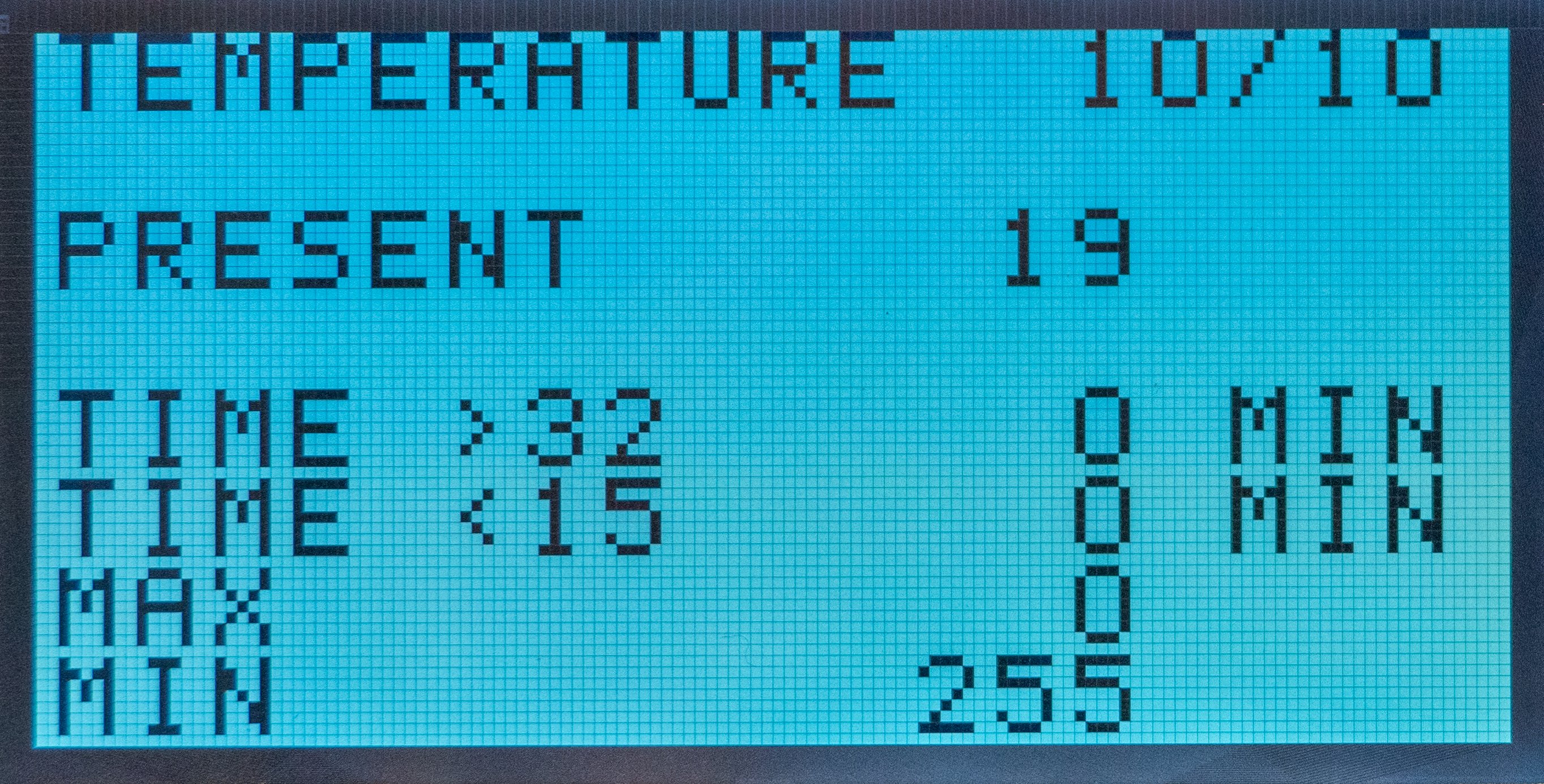
Name on display | Number on display | Translation | Explanation |
|---|---|---|---|
TEMPERATURE | 10/10 | Temperature | 10/10 is page 10 out of 10 shown on the display |
GIFT | 19 | Current | Displays the device's current current temperature in real time. |
TIME > | 32/0 | Time, highest | Shows the highest temperature and how long the highest temperature lasted (in minutes). |
TIME < | 15/0 | Time, minimum | Shows minimum temperature and how long the minimum temperature lasted (in minutes). |
MAX | 0 | Max | Shows the highest temperature the unit has had since it was put into operation. |
MY | 30.0 | My | Shows the minimum temperature the unit has had since it was put into operation. If the lowest temperature shows 255, it means that the temperature sensor is not connected. |
Commissioning - how to start the unit
Connect batteries
Connect / switch on fuses
connect load, alarm and possibly. other connections.
Screw the mains cable into the terminal block and attach the terminal block to the motherboard.
Switch on mains voltage.
The unit works normally when the indicator LED on the outside of the cabinet door lights up with a solid green light. See front panel for other status indications.
It may take up to 72 hours before the batteries are fully charged.
Panel description
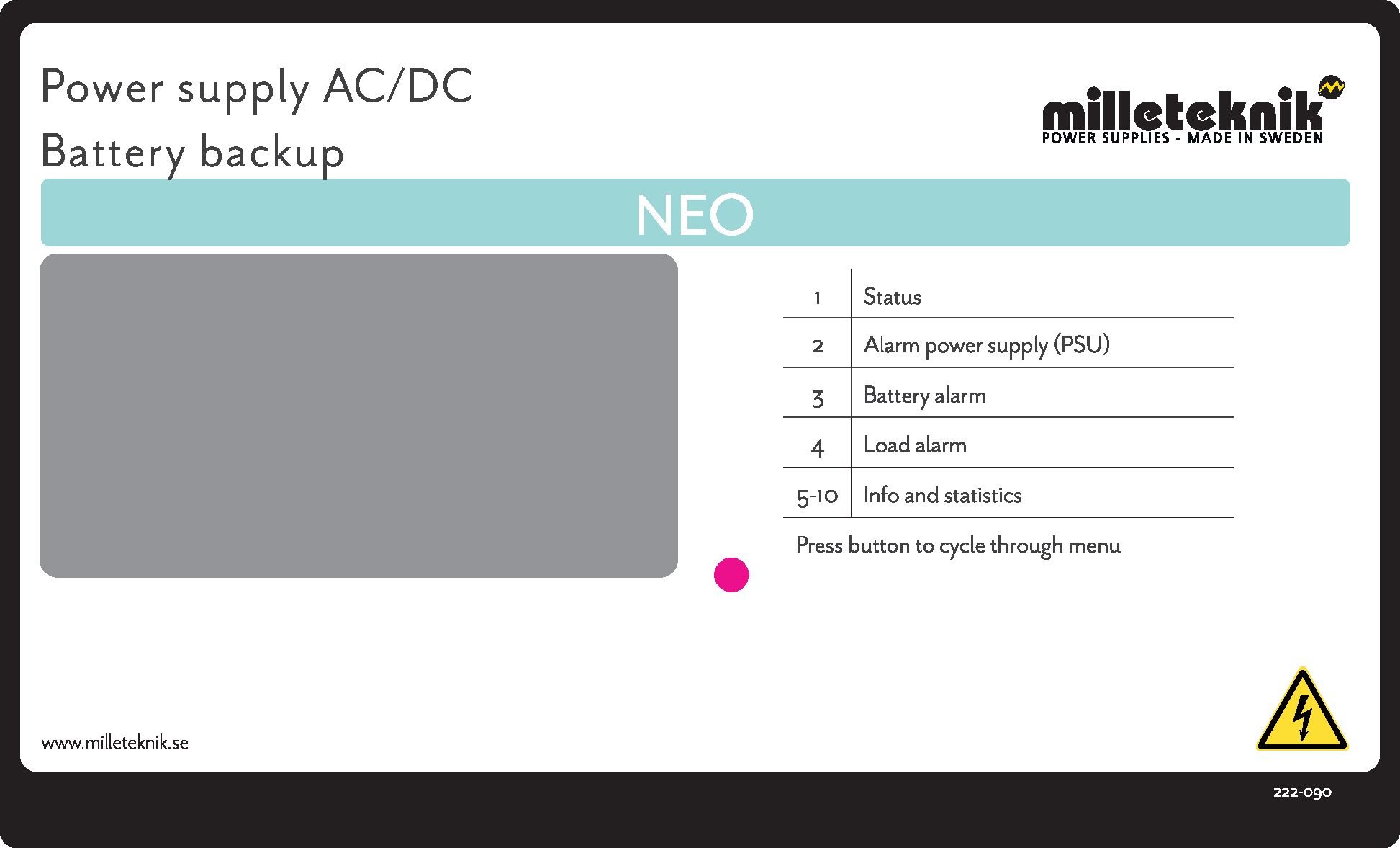
Screen no | Explanation |
|---|---|
1 | Status screen |
2 | Alarm from power supply |
3 | Battery alarm |
4 | Load alarm |
5-10 | Information and statistics |
More information about the status from the screen can be found in the section which describes each screen.
NEO Product Sheet
NEO Battery backup with more alarm functions
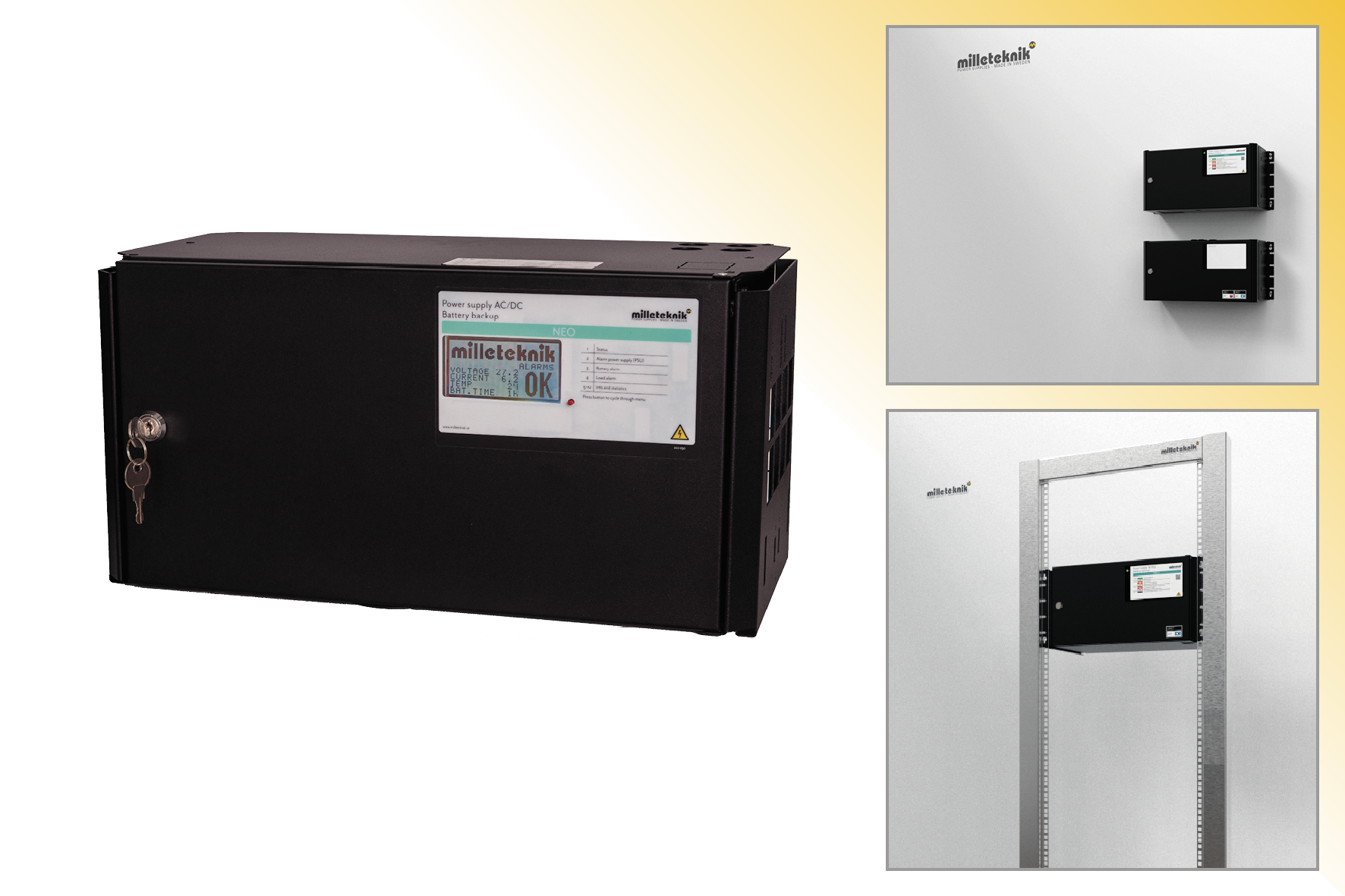 |
NEO FLX M Display is available in 24 V and can be mounted on a wall or in a 19" rack.
Technical specifications
These technical specifications are subject to change without notice.
NEO - Name, article number and e-number
Name | Article number | E-number (SV) |
|---|---|---|
NEO 24V 5A FLX M Display | FM01P10024P050-DSP1 | 52 136 32 |
NEO 24V 10A FLX M Display | FM01P10024P100-DSP1 | 52 136 33 |
NEO 24V 15A FLX M Display | FM01P10024P150-DSP1 | 52 136 34 |
NEO 24V 25A FLX M Display | FM01P10024P250-DSP1 | 52 136 35 |
NEO battery backup for security installations
NEO is normally used in facilities where the requirements are higher regarding greater flexibility, more alarm functions, longer backup operating times or when the battery backup needs to handle higher loads. The NEO series offers controlled charging (intelligent charging), which means that when the batteries are fully charged, they will be electronically disconnected for standby mode for up to 20 days or when the batteries have reached 26.7 V (24 V). By discharging the batteries and recharging them continuously (instead of never using them), the system extends the life of the battery by up to 50%. The batteries automatically connect in less than 50 microseconds when needed.
NEO with display
NEO with display has an external display for status readings and battery capacity setting.
Flexibility
NEO FLX S can have an extra battery box. NEO FLX M and NEO FLX L with 1-4 extra battery boxes. NEO FLX M and NEO FLX L with battery shelves in 19 ”rack *. * The battery boxes and shelves are connected via a 9-pin connector. The battery box has room for up to 2 pcs. 45 Ah batteries per battery box. Battery shelves have room for 2 pcs. 45 Ah batteries (Medium) and up to 2 pcs. 150 Ah batteries (Large) per each battery shelf.
Area of use
NEO supplies power to access systems, alarm systems or other security products in a building that are powered by 24 V DC. The rectifier in the power supply converts 230 V DC down to 24 V DC. Batteries, for example the access system, continue when the power grid goes down. Long life, energy efficient and support is available if something goes wrong, now or in 10 years.
Fixed installation
The product is intended for fixed installation. The battery backup must be installed by a qualified installer.
Regulations and certifications
Requirements that the product meets
EMC: | EMC Directive 2014 / 30EU |
Electricity: | Low voltage directive: 2014/35 / EU |
CE: | CE directive according to: 765/2008 |


Expected operating time in the event of a power failure ( with new batteries)
System voltage | Number of batteries | Battery type | Unit + battery box * | Load: 2 A | Load: 4 A | Load: 8 A | Load: 10 A | Load: 14 A | Load: 18 A |
|---|---|---|---|---|---|---|---|---|---|
24 V | 2 pcs | 20 Ah | 1+0 | 9 h | 3.5 h | 1.5 h | 1 h | 30 min. | 20 min. |
24 V | 2 pcs | 45 Ah | 1+1 | 21 h | 12 h | 4 h | 3 h | 2 h | 1.5 h |
24 V | 4 pcs | 45 Ah (90 Ah) | 1+2 | 42 h | 20 h | 12 h | 8 h | 5 h | 3.5 h |
24 V | 6 pcs | 45 Ah (135 Ah) | 1+3 | 64 h | 30 h | 15 h | 12 h | 9 h | 6 h |
24 V | 8 pcs | 45 Ah (180 Ah) | 1+4 | 82 h | 42 h | 20 h | 16 h | 12 h | 10 h |
* Example: 1 + 2 means that there is 1 battery backup with 2 battery boxes connected. 1 + 0 means that it is a battery backup without a battery box. | |||||||||
Circuit boards - Technical data
Technical data, motherboard: PRO 1
Info | Explanation |
|---|---|
Short name: | PRO 1 |
Product description | Main PCB in battery backup with advanced functions and communication to parent system. |
Own consumption, with relay card | Less than 210 mA. 100 mA without power stage with all relays retracted on external alarm card in normal mode. |
Switching time from mains voltage to battery operation | When batteries are idle: <5 microseconds. When batteries are in charge cycle: 0 (none). Batteries rest for 20-day cycles, after which a charging cycle picks up and charges the batteries for 72 hours. If there is a power failure when batteries are in the charge cycle, there is no switching time. |
Incoming electricity network | 230 V AC -240 V AC, 47-63 Hz. |
Fuse on mains | See table: Fuses. |
Indication | Indicator diode on circuit board / cabinet door |
Alarm
Alarm displayed on indicator LED on the front of the cabinet.
Cell fault in battery or unconnected battery.
Charger fault, undervoltage.
Charger fault, overvoltage.
Low system voltage, system voltage below 24.0 V in mains operation.
Low battery voltage, below 24.0 V DC in case of mains failure.
Power failure alarm.
Sabotage switch.
Fuse fault.
Aged battery
Expanding alarm functions are available via communication or with alarm cards.
Info | Explanation |
|---|---|
Alarm on alternating relay? (Yes No) | Yes |
Load outputs, number | 2 |
Voltage at load output | 27.3 V DC |
Voltage limit, upper, on load output | 27.9 V DC |
Voltage limit, lower, on load output. For battery operation and disconnected mains voltage. | 20 V DC |
Priority (always voltage) load outputs (Yes / No) | |
Maximum load, per output | 10 A |
Maximum load, total, (must not be exceeded). | 10 A |
Load output plus (+) secured? (Yes No) | Yes |
Load output minus (-) secured (Yes / No) | Load output 1 = Yes Load passage 2 = No. |
Fuses on output | Yes, see table: Fuses. |
Fuse | Type |
|---|---|
10 A | T10A |
15 A | T15A |
25 A | T25A |
Mains fuse for 24 V units up to 15 A | T2.5AH250V. Ceramic. |
Mains fuse for 24 v units over to 15 A | T4AH250V. Ceramic. |
Electrical protection | |
|---|---|
Deep discharge protection (Yes / No) | Yes. 12 V units protection at 10V, +/- 0.5 V. 24 V units protection at 20, +/- 0.5 V. |
Surge protection (Yes / No) | Yes |
Overtemperature protection (Yes / No) | Yes |
Short circuit protected = (Yes / No) | Yes |
Technical data, motherboard: PRO 1
Info | Explanation |
|---|---|
Card name: | PRO 1 alarm card |
Version: | 3 |
Product description | Alarm card for PRO1 with alarm on changeover relay. All relays are normally energized and give an alarm in a voltage-free position. |
Own consumption | 30 mA. |
Alarm overview in alphabetical order | Relay 1 * / Alarm output 1 | Relay 2 * / Alarm output 2 | Relay 3 * / Alarm output 3 | Communication (J14: 1-9) | Indicator LED on main card, PCB and LED on door. |
|---|---|---|---|---|---|
Network outages | X | - | - | X | X |
Fuse fault | - | X | - | X | X |
Sabotage switch | - | X | - | X | X |
Fan fault | - | - | - | X | - |
Charger fault, overvoltage | - | X | - | X | X |
Charger fault, undervoltage | - | X | - | X | X |
Cell fault or unconnected battery | - | X | - | X | X |
Low system voltage. ** | - | - | X | X | X |
Low battery voltage (<24.0 V DC) or power failure | - | X | - | X | X |
Overtemperature | - | - | - | X | - |
Undertemperature | - | - | - | X | - |
Undertemperature | - | - | - | X | - |
Short battery life left | - | - | - | X | - |
Aged battery | - | X | - | X | X |
Overcurrent 100%, minute average | - | - | - | X | - |
Overcurrent 80%, daily average | - | - | - | X | - |
Overcurrent 175%, seconds average | - | - | - | X | - |
* Alarm on potential-free relay contact. ** System voltage in mains operation is below 24.0 V. | |||||
Power supply
Power supply - Technical Data LRS-150-24
In: |
|---|
NEO 24V 5A FLX M Display |
Info | Explanation |
|---|---|
Output voltage | 27.3 V |
Output current: | 0 A - 6.5 A |
Output voltage, ripple | 200 mVp-p |
Overvoltage | 28.8 V - 33.6 V |
Voltage recharge, ripple / current limitation | Less than 0.6 Vp-p |
Efficiency | 89% |
Current limitation | 110% - 140% |
Constant voltage | +/- 0.5% |
Regulatory accuracy | + / - 1.0% |
Input current (230 V) | 1,7 A |
Mains voltage frequency | 47 Hz- 63 Hz |
Mains voltage | 230 V AC - 240 V AC |
Brand effect | 156 W |
Temperature range | -30°C - +70°C |
Humidity range | 20% - 90% RH non-condensed |
Power supply - Technical Data RSP-320-24
In: |
|---|
NEO 24V 10A FLX M Display |
NEO 24V 15A FLX M Display |
Info | Explanation |
|---|---|
Output voltage | 27.3 V |
Output current | 0 A - 13.4 A |
Output voltage, ripple | 150 mVp-p |
Overvoltage | 27.6 V - 32.4 V |
Voltage recharge, ripple / current limitation | Less than 1.2 Vp-p |
Efficiency | 89% |
Current limitation | 105% - 135% |
Constant voltage | +/- 0.5% |
Regulatory accuracy | +/- 1.0% |
Input current (230 V) | 2 A |
Mains voltage frequency | 47 Hz- 63 Hz |
Mains voltage | 230 V AC - 240 V AC |
Brand effect | 321.6 W |
Temperature range | -30°C - +70°C |
Humidity range | 20% - 90% RH non-condensed |
Power supply - Technical Data HRP-600-24
In: |
|---|
NEO 24V 25A FLX M Display |
Info | Explanation |
|---|---|
Output voltage | 27.3 V |
Output current | 0 A - 27 A |
Output voltage, ripple | 150 mVp-p |
Overvoltage | 30 V - 34.8 V |
Voltage recharge, ripple / current limitation | Less than 1.2 Vp-p |
Efficiency | 88% |
Current limitation | 105% - 135% |
Constant voltage | +/- 0.5% |
Regulatory accuracy | +/- 1.0% |
Input current (230 V) | 3,6 A |
Mains voltage frequency | 47 Hz- 63 Hz |
Mains voltage | 230 V AC - 240 V AC |
Brand effect | 648 W |
Temperature range | -30°C - +70°C |
Humidity range | 20% - 90% RH non-condensed |
Technical data enclosures
Enclosures - Technical Data FLX M
Info | Explanation |
|---|---|
Name | FLX M |
Enclosure class | IP 32 |
Measure | Height: 224 mm, width 438 mm, depth 212 mm |
Height units | 5 HE |
Mounting | Wall or 19 "rack |
Ambient temperature | + 5 ° C - + 40 ° C. For best battery life: + 15 ° C to + 25 ° C. |
Environment | Environmental class 1, indoors. 20% ~ 90% relative humidity |
Material | Powder coated sheet |
Color | Black |
Cable entries, number | 4 |
Batteries that fit | 2 pieces 12 V, 20 Ah. |
Fan | Yes |
Link to the latest information
Products and software are subject to updates, you will always find the latest information on our website.
Warranty, support, country of manufacture and country of origin
Warranty
The product has a two-year warranty, from the date of purchase (unless otherwise agreed). Support during the warranty period can be reached at support@milleteknik.se or telephone, +46 31-34 00 230. Compensation for travel and / or working hours in connection with locating faults, installing repaired or replaced goods is not included in the warranty. Contact Milleteknik for more information. Milleteknik provides support during the product's lifetime, however, no later than 10 years after the date of purchase. Switching to an equivalent product may occur if Milleteknik deems that repair is not possible. Support costs may (at Milleteknik's discretion) occour after the warranty period has expired.
Support
Do you need help with installation or connections? Our support phone is available: Monday-Thursday 08: 00-16: 00 and Fridays 08: 00-15: 00. Telephone support is closed between 11: 30-13: 15.
You will find answers to many questions at: www.milleteknik.se/support
Phone: +46 31-340 02 30
Support is open: Monday-Thursday 08:00-16:00, Fridays 08:00-15:00. Closed 11:30-13:15.
Spare parts
Contacted support for questions about spare parts.
Support after the warranty period
Milleteknik provides support during the life of the product, but no longer than 10 years after the date of purchase. Replacement for an equivalent product may occur if the manufacturer deems that repair is not possible. Costs for support and replacement are added after the warranty period has expired.
Questions about product performance?
Contact sales: 46 31-340 02 30, e-mail: sales@milleteknik.se
Contact us
Milleteknik AB
Ögärdesvägen 8 B
S-433 30 Partille
Sweden
+46 31-34 00 230
www.milleteknik.se
Country of manufacture
Country of manufacture / country of origin is Sweden. For more information, contact your seller.
Designed and produced by: Milleteknik AB
Designed and produced by Milleteknik AB
Batteries - recommended, not included
Batteries are not included they are sold separately
Batteries are sold separately.
20 Ah, 12 V AGM battery
Fits in | Number of batteries |
|---|---|
NEO 24V 5A FLX M | 2 |
NEO 24V 10A FLX M | 2 |
NEO 24V 15A FLX M | 2 |
NEO 24V 25A FLX M | 2 |
Battery type | V | Ah |
|---|---|---|
Maintenance-free AGM, lead-acid battery. | 12 V | 20 Ah |
Article number | E-number | Article name | Terminal | Measure. Height width depth | Weight per piece | Make |
|---|---|---|---|---|---|---|
MT113-12V20-01 | 5230538 | UPLUS 12V 20Ah 10+ Design Life battery | M5 Bult | 182x77x168 mm | 6.0 kg | UPLUS |
Reserve operating times for different alarm classes - overview
The table shows the requirements for backup operating time and recharging of batteries for different alarm classes.
Important
This is a guide and all times are approximate and may differ from actual times. Load, temperature and other factors come into play, which is why exact time can not be provided.
Applies to new batteries.
Amperage and batteries vary with configuration, check if the configuration can handle batteries and amperage.
Medium current | 7.2 Ah | 14 Ah | 28 Ah | 45 Ah |
|---|---|---|---|---|
Loading | Backup operating time (approx.), Minutes | |||
0.5 A | 450 | 820 | 1650 | 2350 |
1 A | 260 | 485 | 970 | 1460 |
2 A | 150 | 280 | 560 | 920 |
4 A | 90 | 165 | 335 | 550 |
6 A | 67 | 125 | 245 | 405 |
8 A | 57 | 105 | 210 | 350 |
10 A | 44 | 80 | 160 | 270 |
12 A | 38 | 70 | 140 | 235 |
14 A | 33 | 60 | 120 | 200 |
16 A | 28 | 50 | 100 | 170 |
18 A | 25 | 45 | 89 | 150 |
20 A | 23 | 42 | 84 | 142 |
Medium current | 28 Ah | 42 Ah | 65 Ah | 70 Ah |
|---|---|---|---|---|
- | 4 batteries (14 Ah) | 6 batteries (14 Ah) | 4 batteries (20Ah + 45 Ah) | 10 batteries (7 Ah) |
Loading | Backup operating time (approx.), Minutes | |||
0.5 A | 1650 | 2090 | 5574 | 3440 |
1 A | 970 | 865 | 3252 | 2118 |
2 A | 560 | 815 | 1770 | 1329 |
4 A | 335 | 490 | 930 | 864 |
6 A | 245 | 360 | 600 | 605 |
8 A | 210 | 310 | 426 | 544 |
10 A | 160 | 240 | 342 | 414 |
12 A | 140 | 210 | 270 | 363 |
14 A | 120 | 180 | 234 | 311 |
16 A | 100 | 150 | 204 | 286 |
18 A | 90 | 130 | 150 | 254 |
20 A | 84 | 126 | 138 | 241 |
Medium current | 90 Ah | 110 Ah | 135 Ah | 155 Ah |
|---|---|---|---|---|
- | 4 batteries (45 Ah) | 6 batteries (20 Ah + 45 Ah) | 6 batteries (45 Ah) | 8 batteries (20 Ah + 45 Ah) |
Loading | Backup operating time (approx.), Minutes | |||
0.5 A | 4705 | 5796 | 7056 | 8215 |
1 A | 2928 | 3582 | 4392 | 5070 |
2 A | 1836 | 2247 | 2754 | 3230 |
4 A | 1183 | 1438 | 1762 | 2018 |
6 A | 788 | 959 | 1175 | 1345 |
8 A | 748 | 861 | 1048 | 1150 |
10 A | 570 | 689 | 839 | 920 |
12 A | 499 | 603 | 699 | 765 |
14 A | 427 | 516 | 629 | 655 |
16 A | 404 | 499 | 592 | 590 |
18 A | 359 | 444 | 526 | 520 |
20 A | 340 | 420 | 498 | 495 |
Medium current | 180 Ah | 200 Ah | 225 Ah |
|---|---|---|---|
- | 8 batteries (45 Ah) | 10 batteries (20 Ah + 45 Ah) | 10 batteries (45 Ah) |
Loading | Backup operating time (approx.), Minutes | ||
0.5 A | 9408 | 12972 | 11760 |
1 A | 5856 | 7872 | 7320 |
2 A | 3672 | 4548 | 4590 |
4 A | 2365 | 2670 | 2945 |
6 A | 1577 | 1780 | 1960 |
8 A | 1500 | 1558 | 1800 |
10 A | 1140 | 1246 | 1410 |
12 A | 950 | 1038 | 1200 |
14 A | 855 | 890 | 1055 |
16 A | 810 | 902 | 995 |
18 A | 715 | 802 | 885 |
20 A | 680 | 722 | 840 |
Subject to typos.
Address and contact details
Milleteknik AB |
Ögärdesvägen 8 B |
S-433 30 Partille |
Sweden |
+46 31 340 02 30 |
info@milleteknik.se |
www.milleteknik.com |