Warnings and instructions - Read this first!
Read and follow all warnings and instructions below. Failure to heed the warnings and follow the instructions can result in property damage, electrical accidents, fire or serious personal injury.
It is forbidden to carry and transport the device with the batteries installed and connected. If this is not followed, serious internal errors may occur and functional safety may be compromised.
Installation and connection work may only be carried out when the batteries are removed.
Connect the batteries with the correct polarity - check that the battery polarity corresponds to the marking of the battery terminals.
Keep the ventilation openings clear. There must be at least 10 cm of free space on both sides of the unit for the unit's ventilation needs to be met. Inadequate ventilation can lead to damage to the device or to shortened battery life.
The unit must be installed indoors in a non-condensing environment.
The unit must be connected to a protectively grounded network.
Check that all connections are made correctly before turning on the unit.
The device may cause interference in nearby, sensitive radio and TV equipment.
Service and repair of the device may only be performed by the manufacturer or a service representative authorized by the manufacturer.
Warranty and support
The product has a two-year warranty, from the date of purchase. We provide free support by phone, 031-313 45 42 and e-mail, (support@milleteknik. se) during the warranty period. Reimbursement for travel/working time in connection with fault location, installation of repaired or replaced goods is not included in the guarantee.
Milleteknik provides support during the life of the product, but no longer than 10 years after the date of purchase. Costs for support are added after the warranty period has expired.
User manual
Units for uninterrupted power supply of fire, smoke and heat detection systems as well as automatic fire protection and fire extinguishing systems according to EN 54-4 and EN 12101-10
Article | Article number | Product Name i certification | Certificate of Continuity of Performance | Certificate of Conformity |
|---|---|---|---|---|
EN54 24V 1.5A MX S | C000P00024- P015-EN54 | ZSP100-1.5A-07 | CNBOP-PIB No. 1438-CPR-0454 | CNBOP-PIB No. 4271/2021 |
EN54 24V 5.5A MX M | C010P00024- P055-EN54 | ZSP100-5.5A-18 | ||
EN54 24V 7.5A MX L | C010P00024- P075-EN54 | ZSP100-7.5A-40 |
Product description
The power supply units are intended for uninterrupted power supply of 24 V powered fire protection systems, and meet the requirements of the standards
EN 54-4+A1+A2 and EN 12101-10. The reserve power supply is taken from two 12 V valve regulated batteries with lead/acid cells (Valve Regulated Lead Acid, VRLA). The power supply units are intended for wall mounting.
Table 1: Version overview | |||||
|---|---|---|---|---|---|
Article | Power supply, (mains unit). | Charging current | License plate | Battery capacity | |
Imax b | Imax a | ||||
EN54 24V 1.5A MX S | ZSPM-75-05 | 0.5 A | 1.5 A | 1.1 A | 7-9 Ah |
EN54 24V 5.5A MX M | ZSPM-150-10 | 1.0 A | 5.5 A | 4.6 A | 7-20 Ah |
EN54 24V 7.5A MX L | ZSPM-200-33 | 2.0 A | 7.5 A | 5.6 A | 17-45 Ah |
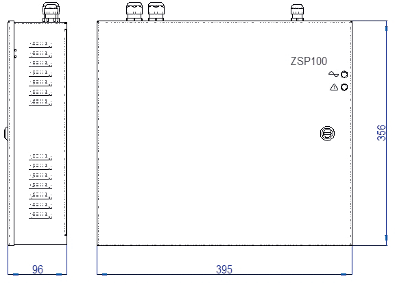 |
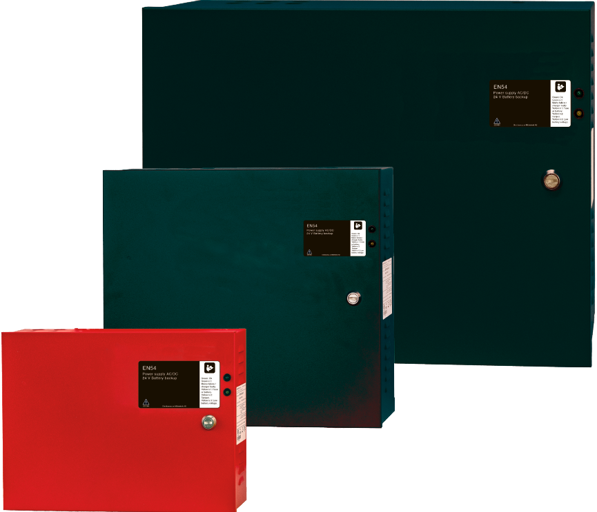
Fig. 1: Product example – EN54 24V 5.5A MX M
The cabinet has knock-out cable entries at the top and on the right side as well as a rectangular opening on the back (side
against the wall) for cabling. Before installing the cabinet, select and determine the routing and location of the cables, break out the cable glands to be used and install the necessary cable glands.
Table 2: Dimensions and weight | |||
|---|---|---|---|
EN54 24V 1.5A MX S | EN54 24V 5.5A MX M | EN54 24V 7.5A MX L | |
External dimensions (W x H x D) (mm) | 340 x 250 x 80 mm | 395 x 356 x 96 mm | 455 x 356 x 187 mm |
Mounting holes, distance: | |||
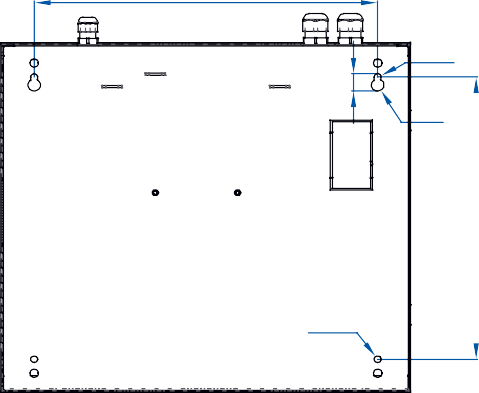
Inside the cabinet (W x H) (mm) | 276 x 182 mm | 350 x 282 mm | 410 x 282 mm |
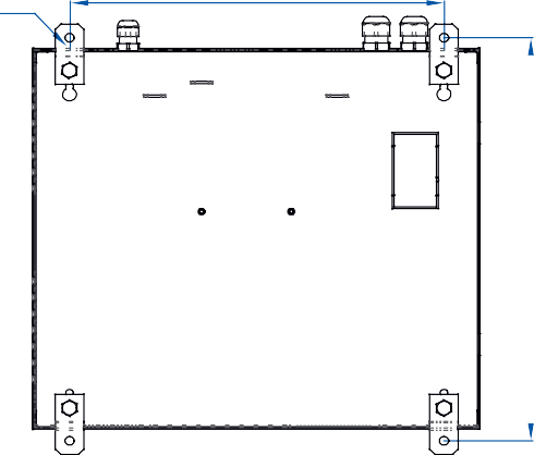
External brackets (W x H) (mm) | 276 x 270 mm | 350 x 370 mm | 410 x 370 mm |
Max. weight without batteries (kg) | 3.1 kg | 4.9 kg | 7.6 kg |
Max. weight with batteries (kg) | 8.4 kg | 17.2 kg | 36.6 kg |
Cable entries on the top | 6 pcs. DW20-RM, 1 pc. DW16-RM | ||
Cable entries on the left side | 3 pcs. DW20-RM, 1 pc. DW16-RM | 6 pcs. DW20-RM, 1 pc. DW16-RM |
 350
350
Fig. 2: Product example - installation dimensions for EN54 24V 5.5A MX M
The cabinet must be attached to the wall with 4 screws. Do not use plastic expander plugs. Unscrew the two screws in the bottom of the cabinet, angle the block out slightly and take it out downwards.
Table 3: Electrical and operating environment data | EN54 24V 1.5A MX S / EN54 24V 5.5A MX M | EN54 24V 7.5A MX L |
|---|---|---|
Rated voltage *1) | 110 / 230 V +10/–15% | |
Nominal output voltage *2) | 27.1V | |
Control range output voltage *3) | 21.0-28.8V | |
Quiescent current consumption from batteries | Max. 17mA | Max. 25mA |
Power consumption from the mains with charged batteries | About 1.7 W | |
Efficiency at rated load with charged batteries | 89% | |
Max. resistance in the battery circuit, (1.5 A and 5.5 A )*4 | 250 mΩ | 100 mΩ |
Number of monitored batteries | 2 | |
Number of separately secured outputs | 2 | 5 |
Ambient temperature in operation | -5 to +55 °C | |
Enclosure class according to EN 60529:2003 | IP 42 | |
Functional class according to EN 12101-10:2007 | A | |
Environmental class according to EN 12101-10:2007 | 2 | |
Protection class according to EN 62368-1:2014 +A11:2017 | I |
*1) If power supply unit ZSP100 consisting of power supply module ZSPM-150 is to be fed from 110 V mains, the mains voltage switch must be placed in position 115 V (this is not necessary for ZSP100 versions with ZSPM-75, ZSPM-200, ZSPM-320).
*2) Applies to operation in trickle charge mode at 25°C.
*3) The control range extends from the start of the constant current charge to the end of the equalization charge.
*4) Fault indication is triggered when the battery circuit resistance reaches this value. Installation and connection
Installation and connection
The power supply unit must be installed firmly with a three-conductor cable, whose phase, neutral and protective earth conductor, (PE) must be connected according to the marking of the terminals. Transient protection is recommended. The mains voltage to the power supply unit must not be interrupted by the fire protection system
main switch. An external installation switch with a rated current of at least 3 A must be installed in the supply to the power supply unit. The supply and the switch must be marked red and provided with clear numbering. Each power supply unit must have its own separate switch.
The batteries must be connected last, after all other connections have been made (24 V outputs and indication circuits) and after connecting the
indicator diode wiring and possible tamper switch. Place the batteries in place on the floor of the cabinet and then place the temperature sensor in place
between the batteries so that it rests against both battery casings. Then connect the battery cables with the correct polarity: red to the positive pole (+) of one battery, black to the negative pole (–) of the other battery. Finally, connect the connection cable between the two batteries.
Power supply EN54 24V 1.5A MX S and EN54 24V 5.5A MX M
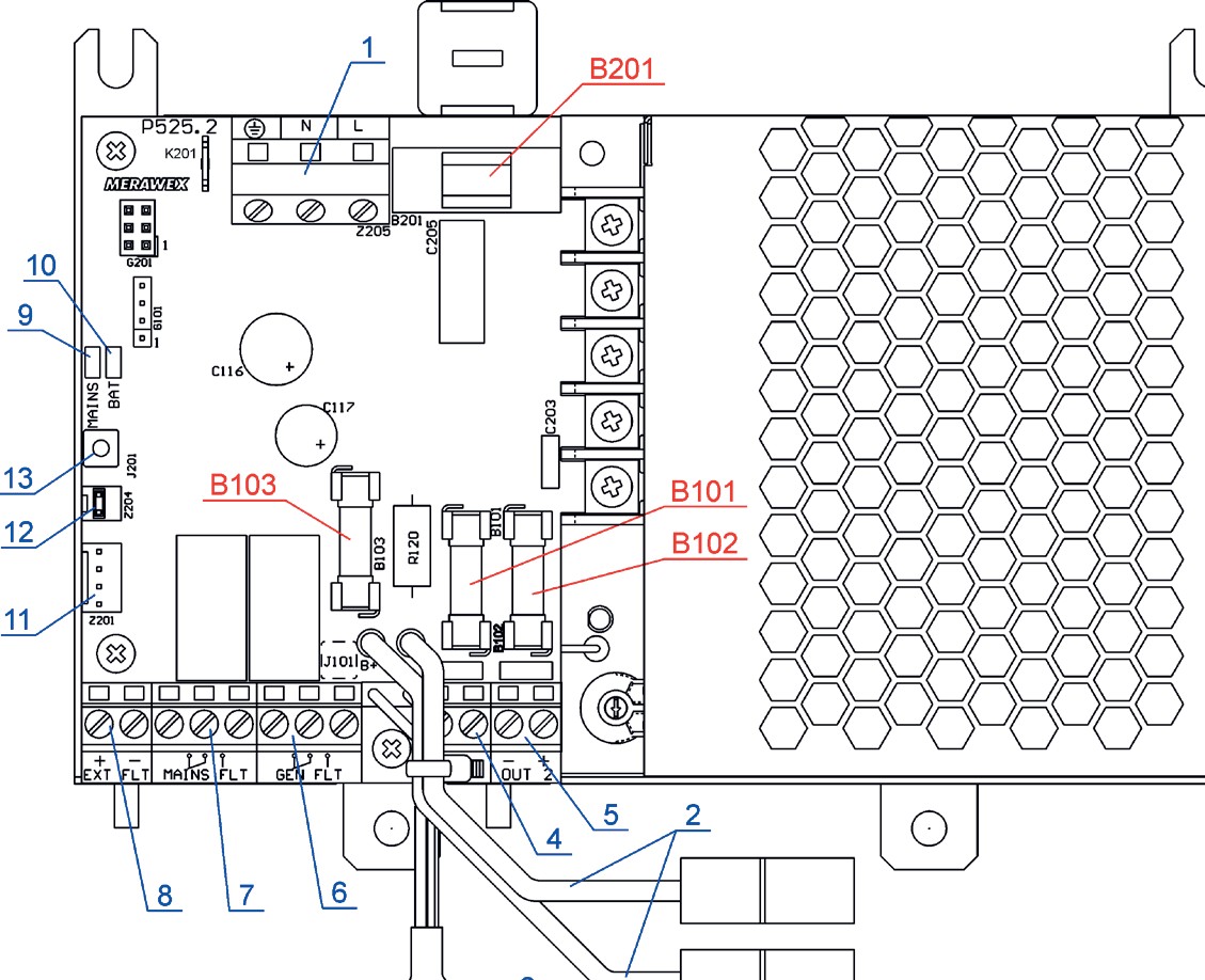 |
Fig. 3: Component location in power supply module ZSPM-75
Table 5: Fuses | |||
|---|---|---|---|
ZSPM-75-05 | ZSPM-150-10 | ||
B201 | Mains voltage input | 4 A sluggish | 6.3 A sluggish |
B101, B102 | Outputs | 3.15 A fast | 6.3 A fast |
B103 | Battery circuit | 6.3 A fast | 8 A fast |
Table 4: Component parts list for ZSPM module (numbering according to Fig. 3) | |||
|---|---|---|---|
No | Name | Marking | Recommended cable |
1 | Mains connection terminal | L, N, | 3-conductor cable with solid conductors and insulation with halogen-free flame retardant *) 0.75–1.5 mm2 |
2 | Battery cables |

3 | Temperature sensor | ||
|---|---|---|---|
4 | Connection terminal load 1 | OUT 1 | 2-conductor cable with solid conductors and insulation with halogen-free flame retardant *) 1 mm2 - 2.5 mm2 |
5 | Connection terminal load 2 | OUT 2 | |
6 | Error signal output, general error | GEN FLT | Relay output. 2-conductor cable for communication, with solid conductors and insulation with flame retardant *) 1 x 2 x 0.8 mm2 |
7 | Error signal output, mains voltage error | MAIN FLT | |
8 | Error signal input, external error | EXT FLT | Optocoupler output. 2-conductor cable for communication, with solid conductors and insulation with flame protection *) 1 x 2 x 0.8 mm2 |
9 | Internal indicator light, green | MAIN | |
10 | Internal indicator lamp, yellow | BAT | |
11 | Connection for indicator diodes | Z201 | |
12 | Connection for tamper switch | Z204 | Factory installed jumper |
13 | Input for indication from set of additional fuse cards | J201 |
*) Cable types for power supply and control of fire protection systems may be prescribed in laws, building codes and other regulations.
Notes
Each fault indication output has 3 relay contacts. The description of the relay connection reflects the conditions when mains voltage is switched off (relay coil de-energized).
The negative pole (–) of the external error input (8) is connected to the battery negative pole (B–). Fault indication is triggered if a short circuit (voltage 0 V) is detected. In this state, approximately 0.25 mA flows between the positive (+) and negative (–) terminals of the input.
If the unit is to be equipped with the tamper contact, connect the tamper contact to the sensor (tamper) on the factory-set jumper on the Z204.
The only user replaceable components are the fuses as per the table below. The replacement fuses must have the same tripping current and
Power supply EN54 24V 7.5A MX L
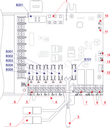 |
Fig. 4: Component location in power supply module ZSPM-200
Table 5: Fuses | ZSPM-200 | |
|---|---|---|
B201 | Mains voltage input | 6.3 A sluggish |
B101 | Battery circuit | 10 A fast |
B301 ... B304 | Load securing 1-4 | 2 A fast |
B305 | Load securing 5 | 10 A fast |
Table 5: Component parts list for ZSPM-200 (numbering according to Fig. 4) | |||
|---|---|---|---|
No | Name | Marking | Recommended cable |
1 | Mains connection terminal | L, N, | 3-conductor cable with solid conductors and insulation with halogen-free flame retardant *) 0.75–1.5 mm2 *1) |
2 | Battery cables | *3) | |
3 | Temperature sensor | ||
4 | Connection terminal load 1,2,3 4 | OUT 1 ... 4 | 2-conductor cable with solid conductors 1.5 mm2 - 2.5 mm2 *1) |
5 | Connection terminal load 5 | OUT 5 | 2-conductor cable with solid conductors 2.5 mm2 - 4 mm2 *2) |
6 | LEDs for tripped output fuses 1 ... 5 | ||
7 | Error signal output, general error | GEN FLT | 2-conductor cable with solid conductors 1x2x0.8 mm2 *2) |
8 | Error signal output, mains voltage error | MAIN FLT | |
9 | Error signal input, external error | EXT FLT | |
10 | Internal indicator light, green | MAIN | |
11 | Internal indicator lamp, yellow | BAT | |
12 | Connection for indicator diodes | Z306 | Factory package with LED package |
13 | Connection for tamper switch | Z202 | Factory installed jumper |
14 | Input for indication from package with additional outputs | J210 |
*1) The connection must be made with a flame-protected halogen-free cable.
*2) The connection should be made with a telecom flame retardant cable for permanent installation.
*3) Connection with cables provided by the power supply manufacturer.
Notes
Each fault indication output has 3 relay contacts. The description of the relay connection reflects the conditions when mains voltage is switched off (relay coil de-energized).
The negative terminal of the external fault input (–) is connected to the negative terminal of the battery (B–
). Fault indication is triggered if a short circuit (voltage 0 V) is detected. In this state, approximately 0.25 mA flows between the positive (+) and negative (–) terminals of the input. If the unit is to be equipped with the tamper contact, connect the tamper contact to the sensor (tamper) on the factory-set jumper on the Z202.
The only user replaceable components are the fuses as per the table below. The replacement fuses must have the same tripping current and tripping characteristic as the replaced fuses.
tripping characteristic as the replaced fuses.
First start
When the power supply is turned on and no errors are present, the status indications according to the Correct Start column in the table below should be displayed. If the indications deviate from this, there are incorrect connections or other errors - see the error descriptions in the appendix.
Before using the power supply unit, two more tests must be carried out.
Uninterruptible power supply test
Switch off the mains voltage with the installation switch. The power supply unit must switch to battery operation and maintain unchanged voltage on both of its outputs. The voltage at the outputs can be checked with a voltmeter.
If the mains voltage is interrupted by removing the mains fuse B201, the mains voltage interruption is only detected after 10 minutes. The fault relay GEN
FLT reacts with a 5 second delay.
Battery circuit monitoring test
Check that the power supply unit is connected to mains voltage, then break the battery circuit by disconnecting one of the battery cables. The battery circuit break is detected at the next test, (detection can take up to 10 minutes).
Table 6: Indications during test | Correct start | Test of mains interruption power supply | Test of battery circuit monitoring | |
|---|---|---|---|---|
Indicator diodes on the cabinet door | ||||
230 V AC | Green | Turn on | Blinks | Turn on |
ALARM | Yellow | Turned off | Turn on | Turn on |
Indicator diodes on the device's motherboard | ||||
MAINS (mains) | Green | Turn on | Turned off | Turn on |
BAT (battery) | Yellow | Turned off | Turned off | Blinks *) |
Indication relays | ||||
MAIN FLT | Mains voltage error | The move | Not drawn | The move |
GEN FLT | General error | The move | Not drawn | Not drawn |


*) If the battery circuit remains disconnected for more than 12 minutes, the BAT indicator light turns solid.
During testing, verify that the GEN FLT fault indication is indeed transmitted correctly to the fire alarm panel.
Operation and maintenance
After installation, the power supply unit only requires regular reading of error indications.
Output voltages and indication levels are factory set.
Do not connect the battery negative pole (B–) with the negative poles of the outputs OUT1 (–) and OUT2 (–)*.
* • Do not connect the minus pole of the battery (B-) to the minus poles OUT1 and OUT2 (-) for each other 1.5 ÷ 5.5 A and
to the negative terminals OUT1 ... OUT5 (-) for version 7.5 ÷ 12 A
The battery pack is connected to the power supply unit only when mains voltage is present and when the battery voltage exceeds 21.6 V. In case of battery failure (the terminal voltage of an individual battery lower than 10 V), the battery is not detected. The alarm indicator light ALARM will flash rapidly when the voltage is between these limits, but the battery will not be connected.
In battery operation mode in case of mains failure, the batteries are automatically disconnected by the low voltage disconnect device (LVDD) when the batteries are discharged below 21 V. After LVDD disconnection, the power supply unit still draws a very small current for internal needs.
The batteries must therefore not be left in this state for any length of time, as they can then be discharged to such a low voltage that they will not be reconnected when the mains voltage returns.
If the power supply unit is to be disconnected from mains voltage for a long time, the batteries must be disconnected. Otherwise, deep discharge can occur, which shortens the life of the batteries.
Battery life shortens drastically with increasing temperature. Every 8 to 10 °C increase in temperature halves battery life.
CNBOP and VdS recommend battery replacement every 4 years of operation, regardless of the condition of the batteries.
The tests described in the section First start, (see page 11.), should be repeated once a year to verify the operation and condition of the power supply unit.
Appendix
Table 7: Indicator diodes on the outside of the power supply cabinet (the door) | |
|---|---|
230 V AC | Green |
0 | Mains voltage missing, battery disconnected (voltage-free state) |
1 | Mains voltage is present, power supply unit/charger is working |
0/1 flashes | Battery operation: mains voltage missing or power supply unit/charger defective*1) |
ALARM | Yellow |
0 | No errors |
1 flashes | Battery operation: mains voltage missing or power supply unit/charger defective*1) Battery circuit break/battery missing or any battery has a pole voltage lower than 10 V and the batteries have been disconnected by the undervoltage protection (LVDD) Battery circuit resistance too high (more than 250 mΩ) or battery fuse blown Load output fuse tripped Fuse in additional fuse module tripped (if connected) Low system voltage - lower than 22 V when mains voltage is present *2) |
0/1 short blinks | External alarm or internal alarm, (if tamper contact is installed). |
0/1 short blinks | Battery detected (U > 10 V) but the battery voltage is too low (U < 21.6 V), which is why the undervoltage protection (LVDD) prevents connection. |
*1) Failure of the power supply unit/charger is detected no later than 10 minutes after the failure occurred (checking is done at the same time as the battery circuit resistance is measured).
*2) This condition can occur when mains voltage returns and battery charging has just started.
Table 8: Indicator diodes on the device motherboard | ||
|---|---|---|
MAINS (mains) Green | 0 | Mains voltage is missing |
1 | Mains voltage available, power supply unit/charger works | |
0/1 flashes | Mains voltage present, power supply unit/charger error *1) | |
BAT (battery) Yellow | 0 | Battery status correct |
1 or | Battery circuit resistance exceeds 250 mΩ (incl disconnected battery or broken battery fuse*2) | |
0/1 flashes | Disconnected battery or broken battery fuse*3. |
*1) Failure of the power supply unit/charger is detected no later than 10 minutes after the failure occurred (checking is done at the same time as the battery circuit resistance is measured).
*2) Measurement of the battery circuit resistance, including checking for battery circuit interruption and tripped battery fuse, takes place every 10 minutes. When excessive battery circuit resistance is detected three times in a row, the indicator lamp BAT lights up and the relay indicator GEN FLT is triggered. This monitoring function allows the system to be checked (eg for maintenance purposes) by temporarily disconnecting the battery circuit without triggering any fault indication, if the battery circuit is reconnected within 2 minutes.
*3) To test this alarm, the battery and battery fuse need to be disconnected and then a single measurement as step *2 describes needs to be made. This allows testing of function without generating a GNT FLT (if reconnection occurs within 2 minutes).
Table 9: Indication relays (0 = relay not pulled, 1 = relay pulled) | |
|---|---|
MAIN FLT | Mains voltage error |
0 | – Mains voltage is missing (only fault in the supply from the mains, does not react to fault in the power supply unit/charger) |
1 | – Mains voltage is present, power supply unit/charger is working |
GEN FLT | General error |
0 | – Always when the alarm indicator light ALARM is lit or flashing *1), *2) |
1 | - No errors |
*1) Failure of the power supply unit/charger is detected no later than 10 minutes after the failure occurred (checking is done at the same time as the battery circuit resistance is measured).
*2) When the mains voltage returns after a mains voltage failure, this indication is given with a 5 s delay.
Recycling of packaging, used product and batteries
 The product packaging is made of recyclable and non-environmentally and health-damaging materials (wood, paper, cardboard and plastic). Packaging materials that are no longer needed must be sorted at source and handed over for recycling.
Products with this label must not be disposed of together with ordinary household waste, but must be handed over to electronics recycling. Used batteries are classified as hazardous waste and must be disposed of in accordance with current regulations for hazardous waste.
1438 | |
|---|---|
MERAWEX Sp. z o. o. - Toruńska 8, 44-122 Gliwice, Poland 16 1438-CPR-0454 | |
EN 54-4:1997 + AC:1999 + A1:2002 + A2:2006, EN 12101-10:2005 + AC:2007 Power supply for fire applications such as smoke hatches & external alarm devices in fire alarm systems. Power supplies for fire indication, heat and smoke control systems, fire protection and fire automation devices ZSP100-1.5A-07, ZSP100-1.5A-18, ZSP100-2.5A-07, ZSP100-2.5A-18 ZSP100-4.0A-07, ZSP100-4.0A-18, ZSP100-4.0A-40 ZSP100-5.5A-07, ZSP100-5.5A-18, ZSP100-5.5A-40 ZSP100-7.5A-18, ZSP100-7.5A-40, ZSP100-7.5A-75 ZSP100-10A-18, ZSP100-10A- 40, ZSP100-10A-75 ZSP100-12A-18, ZSP100-12A-40, ZSP100-12A-75 DWU / DoP: DWU-MX-08 Other technical data: see operational manual |

Milleteknik AB, Ögärdesvägen 8 B, 433 30 Partille
031-34 00 230 www.milleteknik.se