About
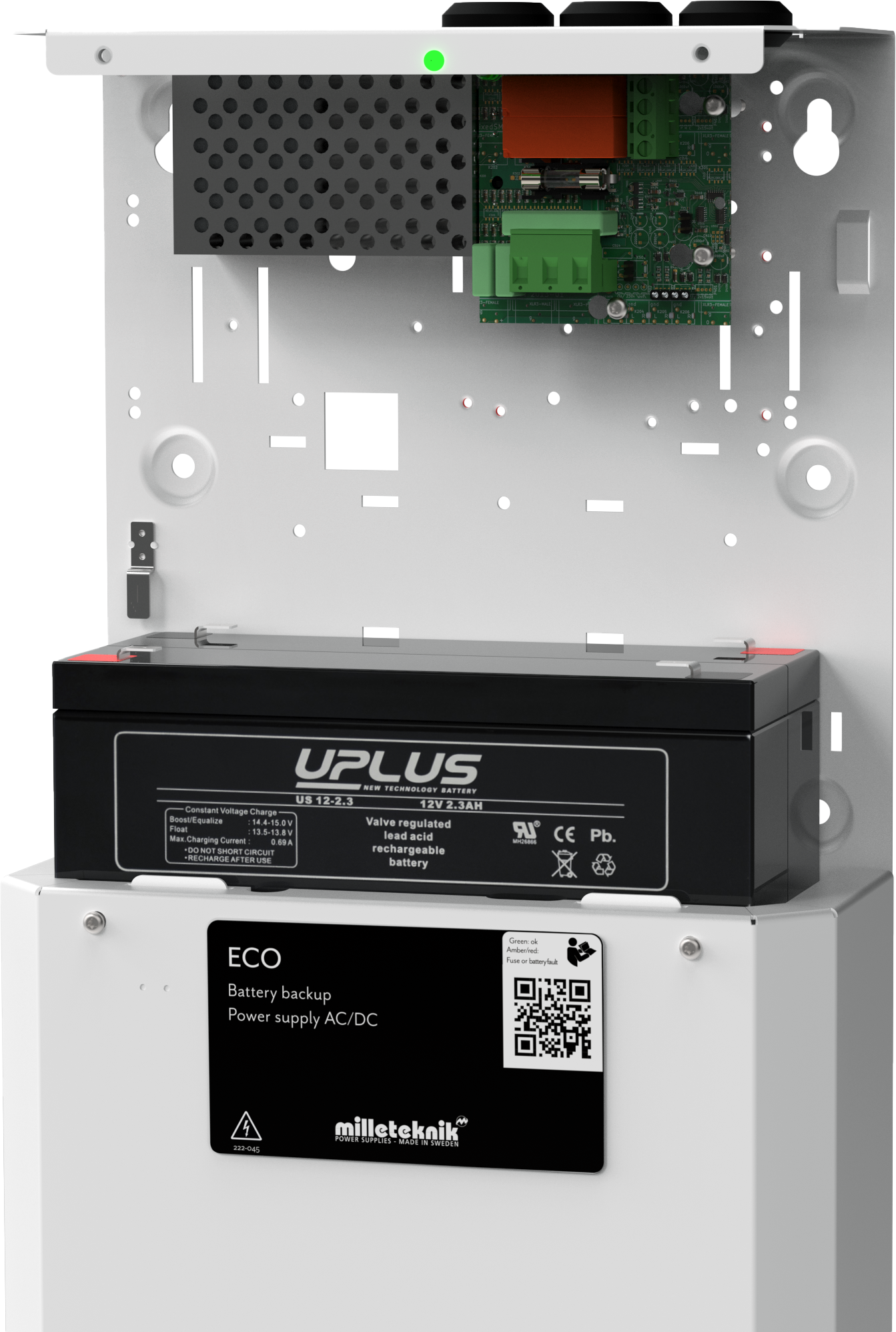
ECO 24V 1A S is a flexible battery backup for use in controlling loads that require a simple and reliable battery backup.
Name, article number and e-number
Name | Article number | E-number (SV) |
|---|---|---|
ECO 24V 1 A S | SM01C10324P010B02 | 52 136 59 |
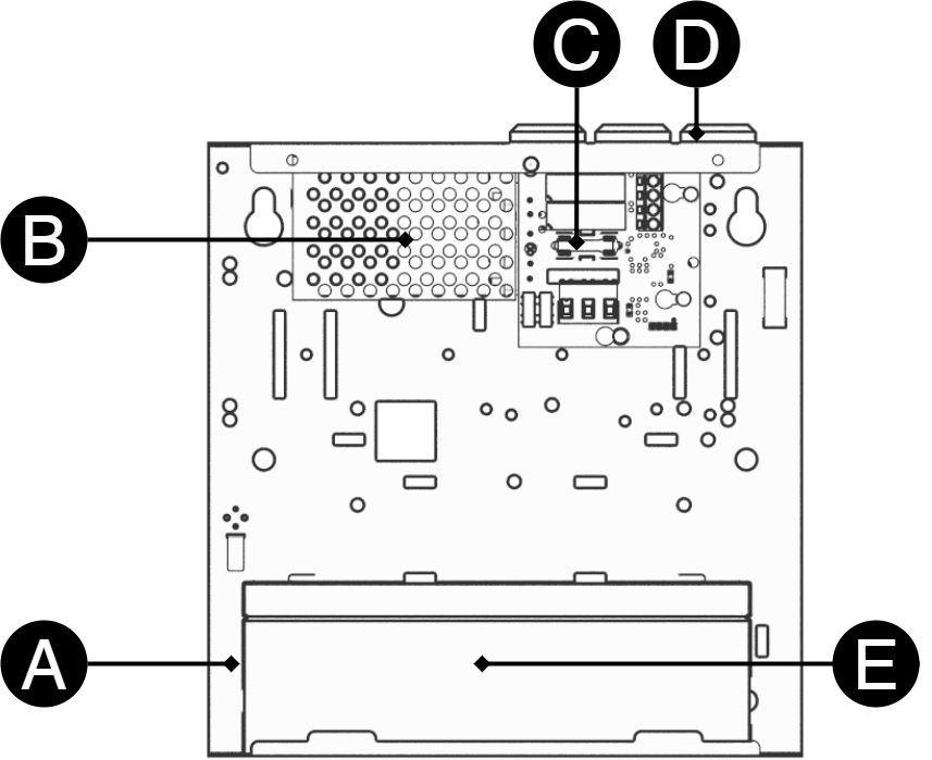
Component overview ECO 24V 1A S
Letter | Explanation |
|---|---|
A | Cabinet in powder-coated sheet metal. |
B | Power supply. |
C | Motherboard. |
D | Cable entries. |
E | Batteries. |
Technical data: CEO 3
Danger
Mains voltage must be disconnected when working with stripped cables. It is the installer's responsibility to ensure that the correct skills are available for connecting 230 V to the unit. Maximum cable area is 4 mm2
Nr | In short | Explanation |
|---|---|---|
1 | P1: 1-3 | Connection to mains, 230 V. |
2 | F6 | Load securing: T2A. |
3 | D1 | Indicator diode, see table below. |
4 | P2: 3-4 | Connect remote control of load output. Shipped assembled with jumper. If the jumper is removed, the load output, see 5 below, is switched off (becomes de-energized) |
5 | P2: 1-2 | Connect load. |
6 | JU2 | JU2 with jumper = 24.0 V. JU 2 without jumper = 26.5 V. The unit is delivered without jumper on JU2. |
7 | JU1 | JU1 with jumper = alarm on buzzer. The unit is delivered with jumper on JU1. The device is delivered without a buzzer. JU1 without jumper = No alarm on buzzer. |
Nr | In short | Indicator diode | Buzzer | Explanation |
|---|---|---|---|---|
3 | D1 | Green | No | OK - normal operation. |
Yellow / orange | Yes if JU1 has a jumper. | Power failure / low battery voltage. Controlled via jumper on JU2. | ||
RED | Yes if JU1 has a jumper. | Triggered load securing |
Commissioning - how to start the unit
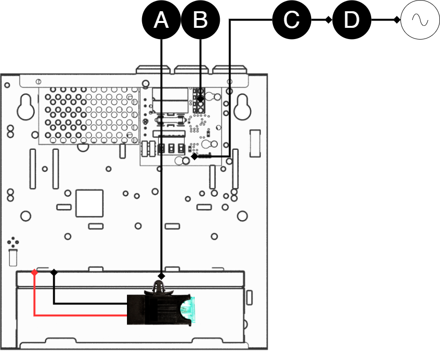
After connection, start-up must take place in the following steps:
Step | Explanation |
|---|---|
A | Insert the fuse into the fuse holder. |
B | Connect load, alarm and other connections. |
C | Connect mains. Screw the mains cable into the terminal block and attach the terminal block to the motherboard. |
D | Switch on mains voltage. |
The unit works normally when the indicator LED on the outside of the cabinet door lights up with a solid green light. See front panel for other status indications.
Charging time for batteries
It can take up to 72 hours before batteries are fully charged during new installation, battery replacement, power outage, or when the device is running on battery power.
Technical data and Product sheets
Product sheet / technical data
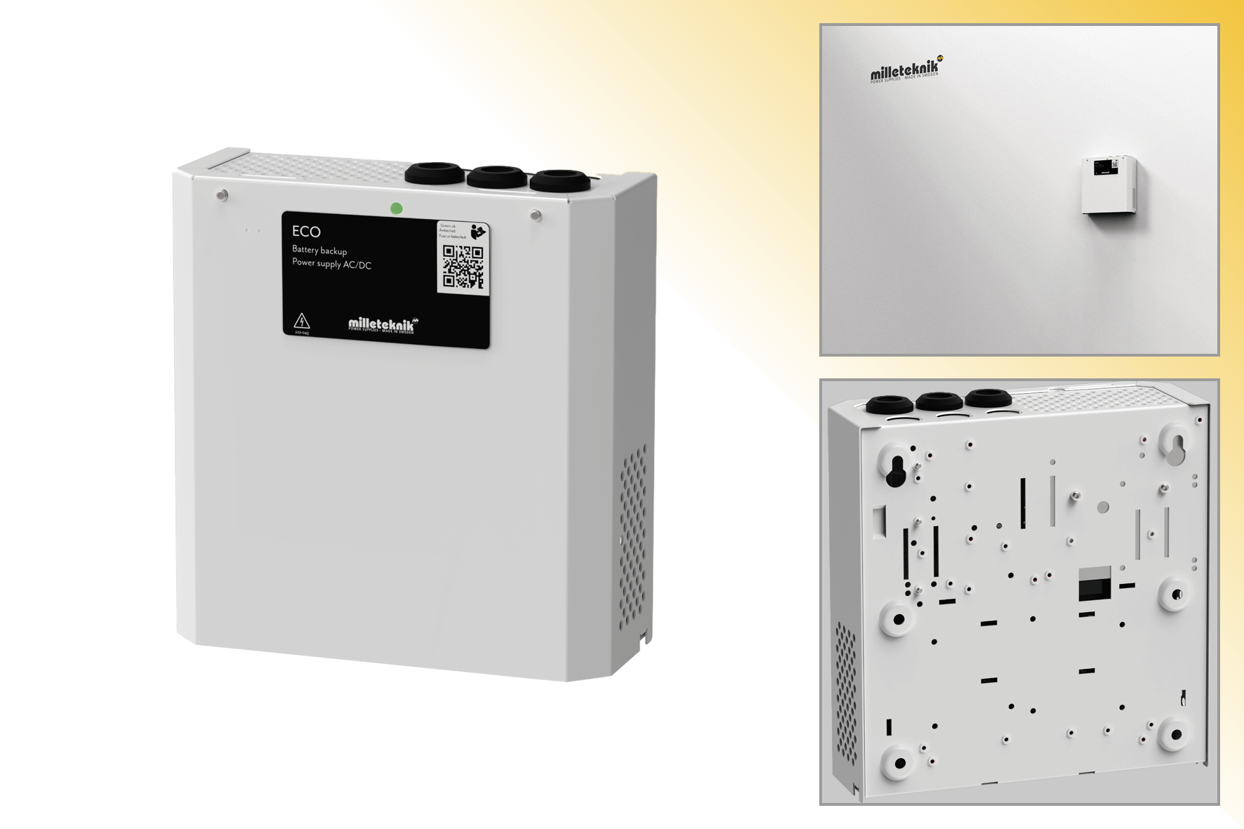
ECO S The unit must be wall-mounted.
Technical specifications
These technical specifications are subject to change without notice.
Name, article number and e-number
Name | Article number | E-number (SV) |
|---|---|---|
ECO 24V 1 A S | SM01C10324P010B02 | 52 136 59 |
About
The ECO series are reliable and smaller battery backups for use with access control systems, locking systems and other loads. The battery backups have controlled charging *.
* Controlled charging prevents batteries from being overcharged, which significantly extends their service life.
Unique for ECO 24V 1A S
ECO 24V 1A S has the option of being supplemented with an external control to cut off the current at the load output.
ECO 24V 1A S is delivered including 2 pcs. 2.3 Ah 6+ Design Life batteries.
Note
Note that ECO 24V 1A S has no alarm output, only visual alarm via LED.
Areas of use
Most used in:
Test before installation of 230 V
"Cold start" means that the battery backup can be commissioned with only the batteries connected without the battery backup being connected to 230 V. This is practical if the installer is not a qualified electrician but still wants to be able to test the system.
Fixed installation
The product is intended for fixed installation. The battery backup must be installed by a qualified installer.
Regulations and certifications
Requirements that the product meets
EMC: | EMC Directive 2014 / 30EU |
Electricity: | Low voltage directive: 2014/35 / EU |
CE: | CE directive according to: 765/2008 |


Expected operating time in the event of a power failure ( with new batteries)
System voltage | Number of batteries | Battery type | Load: 0.1 A | Load: 0.3 A | Load: 0.6 A | Load: 1 A | Load: 1.5 A | Load: 2 A |
|---|---|---|---|---|---|---|---|---|
24 V | 2 pcs | 2.3 Ah | 12 h | 4 h | 2 h | 1 h | 40 min | 20 min |
24 V | 2 pcs | 4.5 Ah | 24 h | 8 h | 4 h | 2 h | 1.5 h | 40 min |
Circuit boards - Technical data
Technical data: CEO 3
Info | Explanation |
|---|---|
Article title | CEO3 |
Measure | 120 x 55 mm x 52 mm |
Own consumption | 40 mA |
Outputs | Output: four load outputs 1-4 which are prioritized load outlets. (= always voltage). |
Insurance | Load output: + secured. |
Max load | Maximum load is 1 A per load output, (T2A is mounted from the factory). |
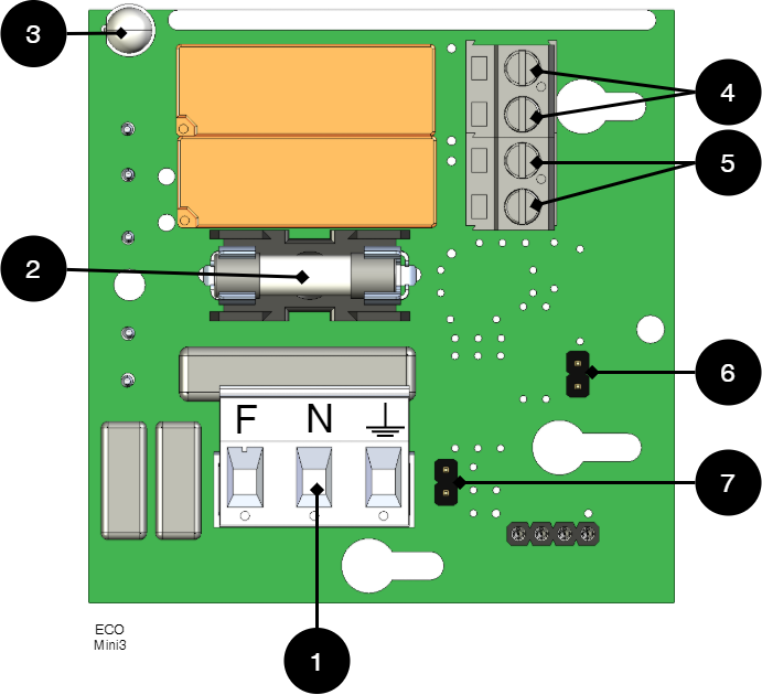
Technical data: CEO 3
Danger
Mains voltage must be disconnected when working with stripped cables. It is the installer's responsibility to ensure that the correct skills are available for connecting 230 V to the unit. Maximum cable area is 4 mm2
Nr | In short | Explanation |
|---|---|---|
1 | P1: 1-3 | Connection to mains, 230 V. |
2 | F6 | Load securing: T2A. |
3 | D1 | Indicator diode, see table below. |
4 | P2: 3-4 | Connect remote control of load output. Shipped assembled with jumper. If the jumper is removed, the load output, see 5 below, is switched off (becomes de-energized) |
5 | P2: 1-2 | Connect load. |
6 | JU2 | JU2 with jumper = 24.0 V. JU 2 without jumper = 26.5 V. The unit is delivered without jumper on JU2. |
7 | JU1 | JU1 with jumper = alarm on buzzer. The unit is delivered with jumper on JU1. The device is delivered without a buzzer. JU1 without jumper = No alarm on buzzer. |
Nr | In short | Indicator diode | Buzzer | Explanation |
|---|---|---|---|---|
3 | D1 | Green | No | OK - normal operation. |
Yellow / orange | Yes if JU1 has a jumper. | Power failure / low battery voltage. Controlled via jumper on JU2. | ||
RED | Yes if JU1 has a jumper. | Triggered load securing |
Power supply
Power supply - Technical Data RS-25-24
In: |
|---|
ECO 24V 1A S |
Output voltage | 27.3 V |
Output current | 0 A - 1.1 A |
Output voltage, ripple | 120 mVp-p |
Overvoltage | 22 V - 27.64 V |
Voltage recharge, ripple / current limitation | Less than 0.6 Vp-p |
Efficiency | 84 % |
Current limitation | 110% - 180% |
Constant voltage | +/- 1.0% |
Regulatory accuracy | * / - 0.5% |
Input current (230 V) | 0,4 A |
Mains voltage frequency | 47 Hz- 63 Hz |
Mains voltage | 85 V AC - 264 V AC |
Brand effect | 26.4 W |
Temperature range | -20°C - +70°C |
Humidity range | 20% - 90% RH non-condensed |
2.3 Ah, 12 V AGM battery
Battery type | V | Ah |
|---|---|---|
Maintenance-free AGM, lead-acid battery. | 12 V | 2.3 Ah |
Article number | E-number | Article name | Terminal | Measure. Height width depth | Weight per piece | Make |
|---|---|---|---|---|---|---|
MT113-12V02-01 | 5230578 | UPLUS 12V 2.3Ah 6+ Design Life battery | Flat pin 4.8 mm | 60x178x35 mm | 1.0 kg | UPLUS |
Technical data enclosures
Enclosures - Technical Data S
Info | Explanation |
|---|---|
Name | S |
Enclosure class | IP 20 |
Measure | Height: 230 mm, width: 216 mm, depth: 85 mm. |
Height units | - |
Mounting | Wall |
Ambient temperature | + 5 ° C - + 40 ° C. For best battery life: + 15 ° C to + 25 ° C. |
Environment | Environmental class 1, indoors. 20% ~ 90% relative humidity |
Material | Powder coated sheet |
Color | White |
Cable entries, number | 3 |
Batteries that fit | 1 pc 12 V 2.3 Ah or 2 pcs 12 V 2.3 Ah or |
Place for fan | No |
Link to the latest information
Products and software are subject to updates, you will always find the latest information on our website.
Warranty, support, country of manufacture and country of origin
Warranty
The product has a two-year warranty, from the date of purchase (unless otherwise agreed). Support during the warranty period can be reached at support@milleteknik.se or telephone, +46 31-34 00 230. Compensation for travel and / or working hours in connection with locating faults, installing repaired or replaced goods is not included in the warranty. Contact Milleteknik for more information. Milleteknik provides support during the product's lifetime, however, no later than 10 years after the date of purchase. Switching to an equivalent product may occur if Milleteknik deems that repair is not possible. Support costs may (at Milleteknik's discretion) occour after the warranty period has expired.
CE marking
Each product has a CE label with information about the product and contact information for the manufacturer. If you are missing something or need more information, you should firstly turn to retailers who will also be able to answer questions about warranty and support. You can always contact the manufacturer if you have questions about the product's performance.
 |
Support
Do you need help with installation or connection?
You will find answers to many questions at: www.milleteknik.se/support
Phone: +46 31-340 02 30
Support is open: Monday-Thursday 08:00-16:00, Fridays 08:00-15:00. Closed 11:30-13:15.
Spare parts
Contacted support for questions about spare parts.
Support after the warranty period
Milleteknik provides support during the life of the product, but no longer than 10 years after the date of purchase. Replacement for an equivalent product may occur if the manufacturer deems that repair is not possible. Costs for support and replacement are added after the warranty period has expired.
Questions about product performance?
Contact sales: 46 31-340 02 30, e-mail: sales@milleteknik.se
Contact us
Milleteknik AB
Ögärdesvägen 8 B
S-433 30 Partille
Sweden
+46 31-34 00 230
www.milleteknik.se
Country of manufacture
Country of manufacture / country of origin is Sweden. For more information, contact your seller.
Designed and produced by: Milleteknik AB
Designed and produced by Milleteknik AB