About translation of this document
User manual in original language in Swedish. Other languages are machine translated and not reviewed, errors may occur.
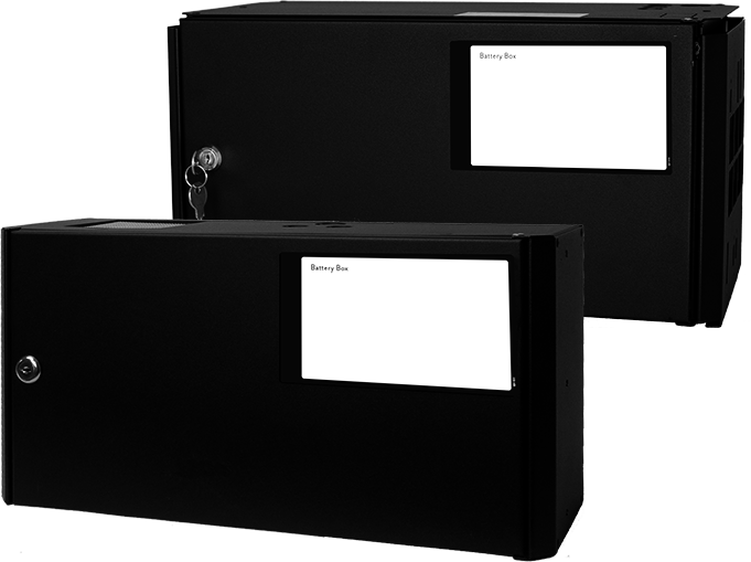
Battery box 24V FLX S
Battery box 24V FLX S has room for four batteries and is mounted under the battery backup on the wall or in a 19" rack.
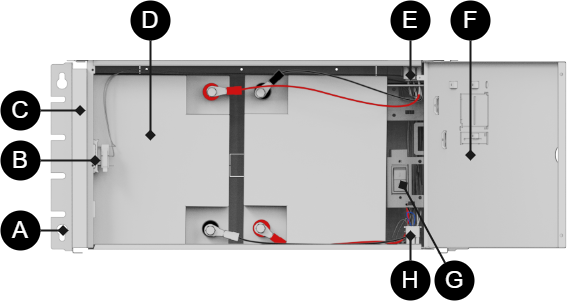
Component overview
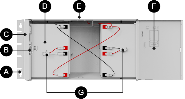 |
Batteries should be placed as in the picture. The picture also gives an overview of connection points for battery cables and battery fuse.
Number | Explanation |
|---|---|
A | Battery cabling for connection to battery backup. |
B | Batteries |
C | Battery fuse |
D | Cabinet in powder-coated sheet metal. Lockable door. |
E | Reversible brackets (4 pcs) for mounting the unit on a wall or in a 19 "rack. |
F | Lockable door. |
G | Battery fuses. |
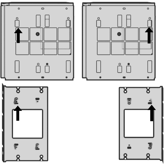
Mounting on a wall or in a 19 "rack
The unit can be mounted in a 19" rack or on a wall. The supplied brackets can be attached in two ways: When mounting on a wall, the brackets must sit backwards, against the wall. When mounting in a 19" rack, the console must be attached at the front of the unit.
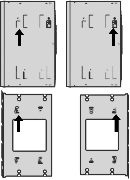
Left bracket facing the front for mounting in a 19 "rack.
Right bracket facing the back for wall mounting.
Important
Leave 100 mm free around the air vents.
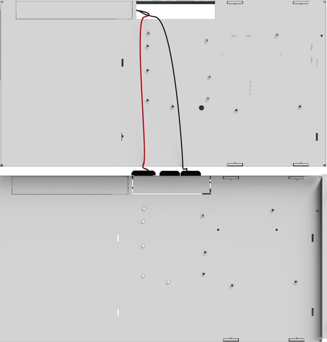
Mounting Battery box 24V FLX S for battery backup in FLX S housing
The battery box is mounted on a wall or in a 19" rack, below the battery backup.
Cable entries are located at the top of the housing and in the middle on its back.
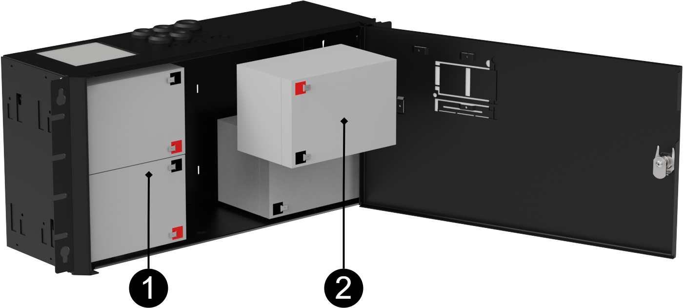
Placement of batteries in Battery box 24V FLX S
No . | Explanation |
|---|---|
1 | Insert in the the first batteries. If there is a tamper contact here, the battery must be pushed in behind the tamper contact. |
2 | Insert the other two batteries. |
Connection battery box with battery backup
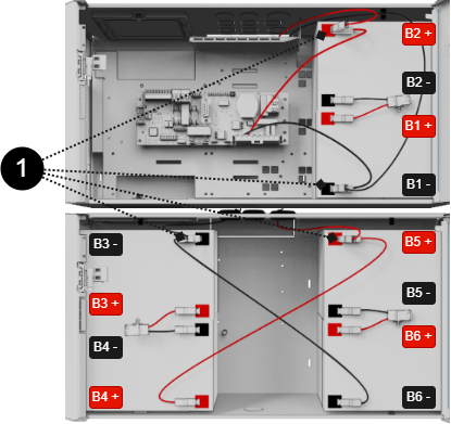
The picture shows a battery backup with extra battery box with 2 batteries.
The picture also gives an overview of connection points for battery cables and battery fuses.
Battery cables | Explanation |
|---|---|
B1+ | Connects to fuse |
B1- | Cable from motherboard is connected to battery |
B2+ | Cable from motherboard is connected to battery |
B2- | Connects to fuse |
B3+ | Connects to fuse |
B3- | Connected via connector to battery in battery backup |
B4+ | Connected via connector to battery in battery backup |
B4- | Connects to fuse |
B5+ | See B4+ |
B5- | Connects to fuse |
B6+ | Connects to fuse |
B6- | See B3- |
Number | Explanation |
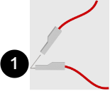
|---|---|
1 | Dual cabling, one for motherboard and one for connection connector. |
Battery box 24V FLX M
Battery box 24V FLX M has room for two 45 Ah batteries and is mounted below the battery backup on a wall or in a 19 "rack.
Batteries and certificates
Batteries must be new during installation and battery replacement in order to maintain warranty and certified standards.
Always use the same (type and manufacturer) batteries with which the device is certified.
Component overview
 |
Batteries should be placed as in the picture. The picture also gives an overview of connection points for battery cables and battery fuse.
Number | Explanation |
|---|---|
A | Bracket, reversible for wall mounting or 19 "rack. |
B | Sabotage contact, If alarm class 3 (SSF) is to be met, the sabotage contact must be on the wall. |
C | Cabinet in powder-coated sheet metal. Lockable door |
D | Batteries. |
E | Connection to battery backup. |
F | Lockable door. |
G | Battery fuse. |
H | Connection to the next battery box |
Mounting on a wall or in a 19 "rack
The unit can be mounted in a 19 ”rack or on a wall. The included brackets can be attached in two ways: When mounting on a wall, the brackets must sit backwards, against the wall. When mounting in a 19 ”rack, the console must be at the front edge of the unit.
Left bracket facing the front for mounting in a 19 "rack.
Right bracket facing the back for wall mounting.
Important
Leave 100 mm free around the air vents.
Mounting battery box with battery backup
The battery box is pushed in during the battery backup, (or previous battery box). The battery box is then screwed to a rack or wall. The two enclosures must meet each other without gap.
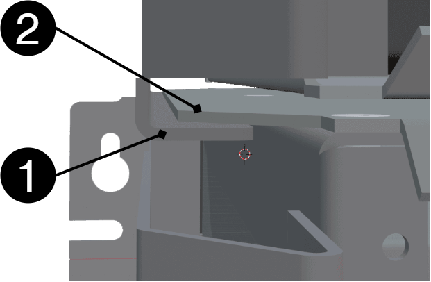
Nr | Explanation |
|---|---|
1 | Track in battery backup. |
2 | Protruding part on the roof of the battery box. |
Placement of batteries
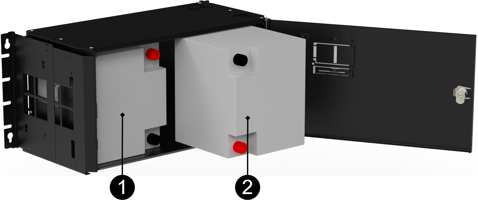
No | Explanation |
|---|---|
1 | Slide the first battery. If there is a tamper connector here, the battery must be pushed in behind the tamper connector. |
2 | Slide in the second battery. |
Connection to batterybox
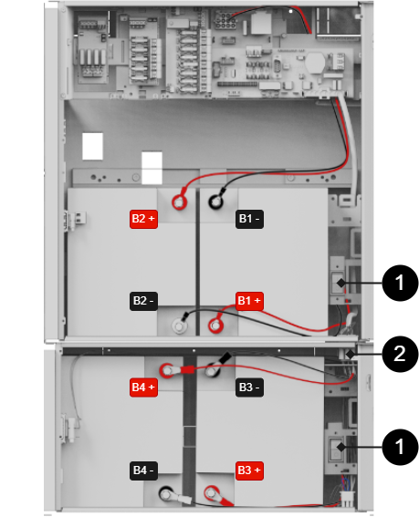
The picture also gives an overview of connection points for battery cables and battery fuses.
Battery cables | Explanation |
|---|---|
B1+ | Connects to fuse . |
B1- | Cable from motherboard is connected to battery . |
B2+ | Cable from motherboard is connected to battery . |
B2- | Connects to fuse . |
B3+ | Connects to fuse . |
B3- | Connected via connector to battery in battery backup . |
B4+ | Connected via connector to battery in battery backup . |
B4- | Connects to fuse . |
Number | Explanation |
|---|---|
1 | Battery fuse. |
2 | Connect battery backup and battery box with white square connector. |
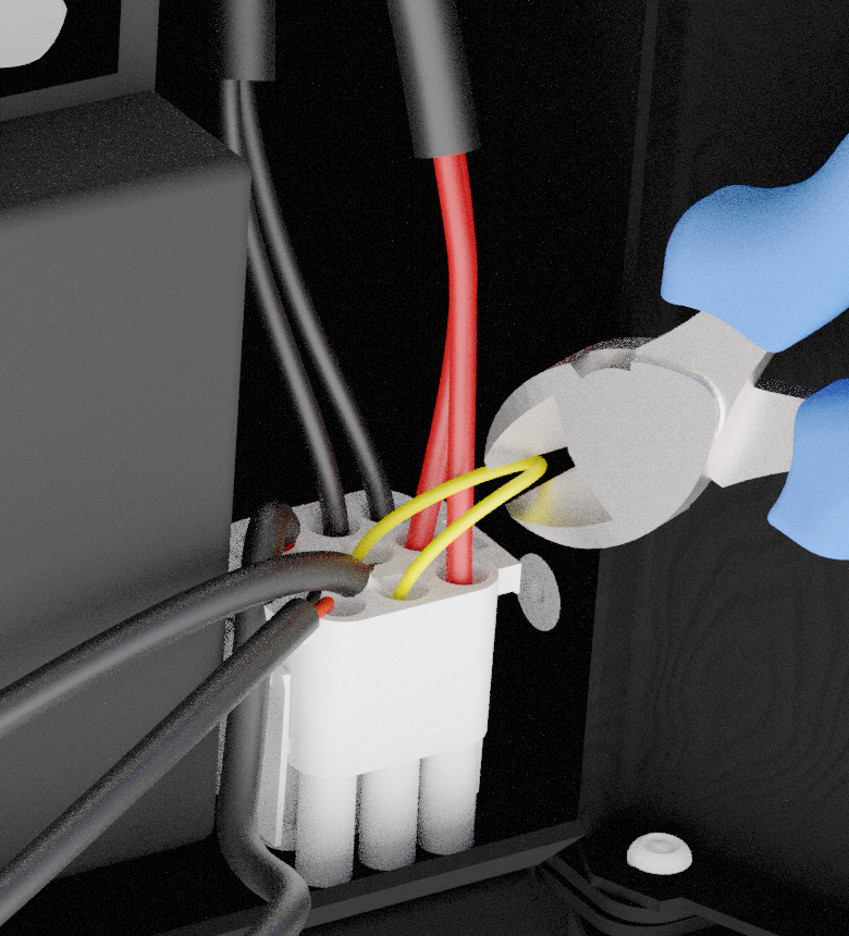
Wiring diagram and jumper
Alarms for tamper contact are connected in series and therefore the loop must be unbroken to the last battery box wiring. Jumper closes the loop on each wiring that goes from battery backup to battery box and in order for an alarm to be given on the tamper connector in the battery box, a yellow jumper on wiring must be cut. Do not cut the jumper on the last wiring in the battery box, as sabotage alarms will not be given in any connected battery backup or battery box.
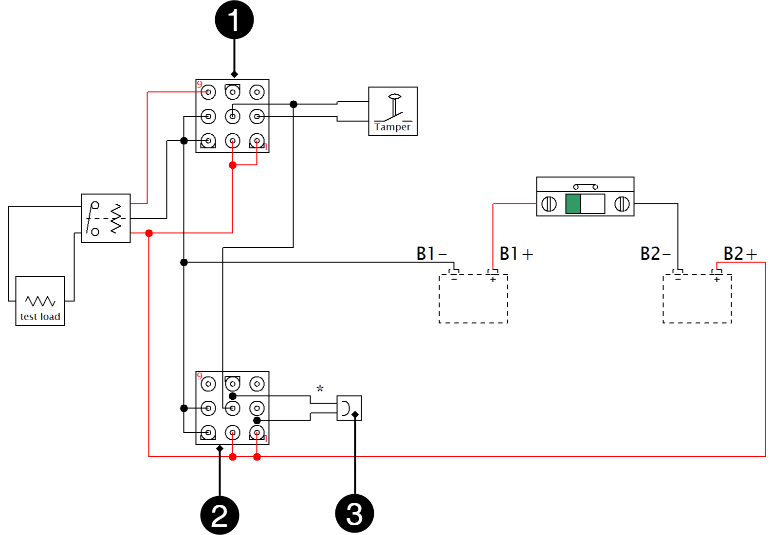
Number | Explanation |
|---|---|
1 | IN - incoming connection |
2 | OUT - outgoing connection |
3 | Jumper on base on outgoing connection |
Devices | Yellow jumper - where to cut / not cut | Where the end of the loop should be |
|---|---|---|
Battery backup without battery box | Do not cut the jumper | Jumper should remain in battery backup |
Battery backup + 1 battery box | Cut jumper from battery backup | Jumper must remain in battery box 1 |
Battery backup + 2 battery boxes | Cut jumper in battery backup and from battery box 1 | Jumper must remain in battery box 2 |
Adjustment of tamper switch
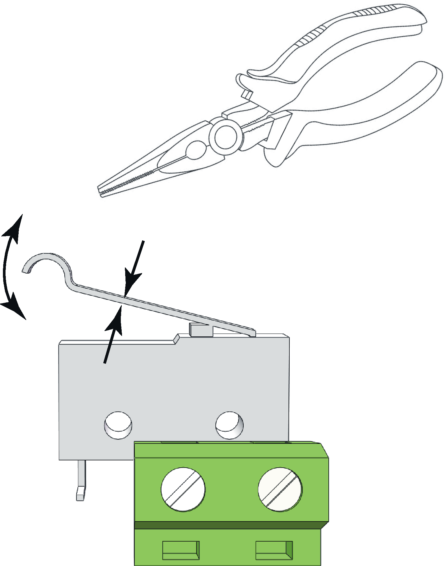 |
The tamper switch lever must be in the closed position when the cabinet door is closed. If the alarm goes off ("tamper alarm"), the lever may needs to be adjusted.
The lever is adjusted by the following steps:
Pinch with pliers in the middle of the lever.
Carefully adjust the lever in the desired direction (up / down).
Check by closing the door. A click is heard when the contact is closed.
Notice
Tamper switch will not give an alarm when closed and locked the door.
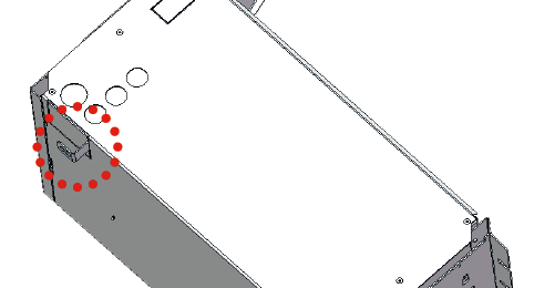
Tamper switch and alarm class 3/4 according to SSF1014
Tamper switch must be attached to the wall to comply with alarm class 3/4 according to SSF1014.
The tamper switch must be connected to the system board.
If the distance is long from the wall when mounting in a rack, for example, a spaccer is needed. It is the installer's responsibility to install the appropriate spacer. The tamper switch in the cabinet must end when the cabinet door is closed. If the alarm goes off ("tamper alarm" / alarm to the control panel), the lever may need to be adjusted.
Tolerance levels for tamper contact: Alarm must be triggered when: Opening the cabinet door; > 1 mm. Breaking unit from wall:> 2.5 mm.
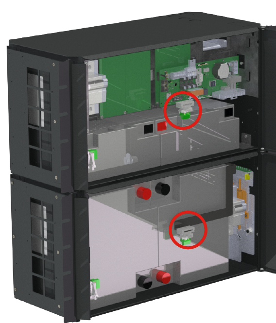
The picture shows location in battery backup and battery box.
Maintenance
The system with the exception of batteries is maintenance-free when installed in an indoor environment.
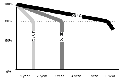
About batteries
Batteries generate electricity through a chemical process and there is thus a natural degradation of capacity. The biggest factor in battery life is temperature. The higher the temperature, the shorter the battery life. The date of manufacture stamped on the battery and the service life (as stated by the battery manufacturer). An ideal temperature is 20 °C both in operation and in storage. Higher ambient temperature greatly reduces the service life. Thus, actual lifespan varies when used. Batteries should be replaced after half specified (from the battery manufacturer) lifetime for safe operation. Batteries purchased through the manufacturer of the battery backup have a lifespan (from the battery manufacturer) of between 10-12 years with recommended replacement after 5-6 years.
battery change
If possible, disconnect mains (voltage) when replacing the battery.
Disconnect battery cables. Note how battery cables are mounted before removing them.
Remove battery fuse between batteries.
Insert and fasten the new batteries.
Connect the battery cables in the same way as before.
Connect battery fuse between batteries.
Switch on mains voltage. The indicator LED may not be green (up to 72 hours), until the batteries are charged.
In order for the system to measure the capacity of new batteries, the device needs to clear previous battery capacity. Dip-switch 8 performs a software reset which, among other things, resets alarms. See Resetting data after battery change (Dip-switch 8)
Test the system by briefly disconnecting the mains voltage, (= the load is driven by the batteries), and then switch on the mains voltage again.
Battery recycling
All batteries must be recycled. Return to manufacturer or return to recycling station.

Maintenance schedule batteries
The maintenance schedule applies to batteries made by UPLUS and with the following serial names: US, USL, USF, and for batteries made by XLENT POWER with serial names XLT and XLL. For maintenance instructions see separate document "care instructions valve-regulated lead-acid battery”.
Series designation | Battery type | Replace battery after |
|---|---|---|
XLT | 3-5 years | 2-3 years |
US | 6-9 years | 3-5 years |
USL | 10-12 years | 5-7 years |
USF | 12 years | 8-10 years |
* battery life depends mainly on ambient temperature and charging current. An AGM battery should never be charged with more than 30% of its rated capacity. The battery will be fully charges, but the charning current must not excced 30% of its rated capacity. | ||
Charging voltage from power supply | 12 V units | 24 V units | 48 V units |
|---|---|---|---|
Minimum charging voltage | 13.6 V | 27.2 V | 54.4 V |
Maximum charging voltage | 13.7 V | 27.4 V | 54.8 V |
Tolerance | +/- 0.5% | +/- 0.5% | +/- 0.5% |
terminal voltage | After 15 minutes of rest / charging. |
|---|---|
Minimum terminal voltage | 12.9 V |
Maximum allowable difference between battery pairs | 0.5 V |
New battery with terminal voltage below 12.0 V is defective and should be reported to the supplier. | |
Temperature in battery backup | Temperature |
|---|---|
Lowest | 15 ° C |
Recommended | 20 ° C - 25 ° C |
Highest | 32 ° C |
Warranty is valid only if the temperature is within these levels. | |
Installation control batteries
Check that the battery is completely clean and that the terminals are free from corrosion.
Check and note the temperature in the battery compartment.
Check the terminal voltage of each battery before installation. If the difference between the batteries exceeds 0.5 V, the battery loop should be equalized in connection with installation. If any battery has a terminal voltage of less than 12V, this battery must be replaced with a new battery and reported to the supplier.
Connect the battery and check the charging voltage. The charging voltage should be between 2.25 V - 2.27 V per cell = between 13.5 V - 13.62 V for a 12 V system and between 27.0 V - 27.24 V for a 24 V system.
Year-round inspection
Check that the battery is completely clean and that the terminals are free from corrosion. If there is corrosion on the terminals: Check that the battery does not leak acid. Then clean the terminals and reconnect the battery. Then lubricate with battery terminal grease over the connected terminal.
Check and note the temperature in the battery compartment.
Check and note the average current.
Check that all connections are securely fastened and that there is no gap in the connection.
Check that the fan (if units have a fan) is working properly. Clean the fan if necessary.
Check the charging voltage by measuring with a multimeter between the connection points + & amp; -. The charging voltage should be between 2.25-2.27 volts per cell = between 13.5-13.62V for a 12V system and between 27-27.24V for a 24V system.
Turn off the rectifier and let the batteries rest for 10 - 15 minutes. Then measure the terminal voltage of each battery. After resting, the terminal voltage must be between 12.9 V - 13.5 V.
Product sheet / Technical data: Battery box 24 V FLX S, Battery box 24 V FLX M
Copyright © Milleteknik AB
Alla uppgifter publiceras med reservation för fel. Ny dokumentation publiceras utan föregående meddelande.
Technical specifications: Battery box 24V FLX S and Battery box 24V FLX M - area of use
The battery box can be mounted in a 19" rack or on a wall. The enclosure is lockable and two pairs of keys are included.
A battery box is used to extend the reserve operating time of a battery backup or to allow for higher currents in a rated system. You can find more about possible average currents in the battery backup's manual.
Batteries and certificates
Batteries must be new during installation and battery replacement in order to maintain warranty and certified standards.
Always use the same (type and manufacturer) batteries with which the device is certified.
Manufacturer support
Manufacturers provide support for the life of the product, however, for a maximum of 10 years after the date of purchase. Switching to an equivalent product may occur if the manufacturer deems that repair is not possible. Support costs will be added after the warranty period has expired.
Product life cycle, environmental impact and recycling
The product is designed and constructed for a long service life, which reduces the environmental impact. The product's service life depends on, among other things, environmental factors, mainly ambient temperature, unforeseen load on components such as lightning strikes, external damage, handling errors, and more. Products are recycled by being handed over to the nearest recycling station or sent back to the manufacturer. Contact your distributor for more information. Costs that arise in connection with recycling are not reimbursed.

Tekniska data Battery box 24V FLX S Battery box 24V FLX M
System voltage: | 24 V. |
Battery capacity, Battery box 24V FLX S | Two 7.2 Ah or two 14 Ah. |
Battery capacity, Battery box 24V FLX M | Two 45 Ah. |
Battery type: | AGM lead acid. |
Enclosure: | Powder coated sheet. |
Mounting: | Wall or 19 "rack. |
Country of manufacture | Sweden |
Battery box warranty
The product has a five-year warranty, from the date of purchase. Support during the warranty period is reached via the contact information on the CE label. Compensation for travel and / or working hours in connection with locating faults, installing repaired or replaced goods is not included in the guarantee. Batteries are not covered by the warranty.
CE marking
Each product has a CE label with information about the product and contact information for the manufacturer. If you are missing something or need more information, you should firstly turn to retailers who will also be able to answer questions about warranty and support. You can always contact the manufacturer if you have questions about the product's performance.
 |
Technical data enclosures
Enclosures - Technical Data FLX S
Info | Explanation |
|---|---|
Name | FLX S |
Enclosure class | IP 32 |
Measure | Height: 222 mm, width 437 mm, depth 145 mm |
Height units | 5 HE |
Mounting | Wall or 19 "rack |
Ambient temperature | + 5 ° C - + 40 ° C. For best battery life: + 15 ° C to + 25 ° C. |
Environment | Environmental class 1, indoors. 20% ~ 90% relative humidity |
Material | Powder coated sheet |
Color | Black |
Cable entries, number | 4 |
Batteries that fit | 2 pcs 7.2 Ah or 4 pcs 14 Ah. |
Place for fan | Yes |
Enclosures - Technical Data FLX M
Info | Explanation |
|---|---|
Name | FLX M |
Enclosure class | IP 32 |
Measure | Height: 224 mm, width 438 mm, depth 212 mm |
Height units | 5 HE |
Mounting | Wall or 19 "rack |
Ambient temperature | + 5 ° C - + 40 ° C. For best battery life: + 15 ° C to + 25 ° C. |
Environment | Environmental class 1, indoors. 20% ~ 90% relative humidity |
Material | Powder coated sheet |
Color | Black |
Cable entries, number | 4 Knockout for Battery connector |
Batteries that fit |
2 pcs 12 V, 45 Ah. |
Technical data: Tamper switch
Name | T-Tamperswitch |
Type | Microswitch |
Voltage | 12 V / 24 V |
Battery recycling
All batteries must be recycled. Return to manufacturer or return to recycling station.
Batteries - recommended, not included
Batteries are not included they are sold separately
Batteries are sold separately.
Battery combinations withBattery box 24V FLX S, (14 Ah batteries)
Battery capacity (Ah) | Battery type | Number of batteries | Batteries in unit |
|---|---|---|---|
14 Ah | 14 Ah | 2 pcs. | 2 in Battery Backup |
42 Ah | 14 Ah | 6 pcs | 2 in Battery Backup 4 in Battery Box |
70 Ah | 14 Ah | 10 pieces. | 2 in Battery Backup 4 in Battery Box 4 in battery box 2 |
Battery combinations Battery box 24V FLX M and battery backup (20 Ah batteries)
Battery capacity (Ah) | Battery type | Number of batteries | Batteries in unit |
|---|---|---|---|
20 Ah | 20 Ah | 2 pcs | 2 in Battery Backup |
45 Ah | 45 Ah | 2 pcs | 0 in Battery Backup 2 in Battery Box 1 |
65 Ah | 20 Ah + 45 Ah | 4 st | 2 in Battery Backup 2 in Battery Box 1 |
90 Ah | 45 Ah | 4 st | 0 in Battery Backup 2 in Battery Box 1 2 and Batteribox 2 |
110 Ah | 20 Ah + 45 Ah | 6 st | 2 in Battery Backup 2 in Battery Box 1 2 and Batteribox 2 |
135 Ah | 45 Ah | 6 st | 0 in Battery Backup 2 in Battery Box 1 2 and Batteribox 2 2 and Batteribox 3 |
155 Ah | 20 Ah + 45 Ah | 8 st | 2 in Battery Backup 2 in Battery Box 1 2 and Batteribox 2 2 and Batteribox 3 |
180 Ah | 45 Ah | 8 st | 0 in Battery Backup 2 in Battery Box 1 2 and Batteribox 2 2 and Batteribox 3 2 and Batteribox 4 |
200 Ah | 20 Ah + 45 Ah | 10 pieces | 2 in Battery Backup 2 in Battery Box 1 2 and Batteribox 2 2 and Batteribox 3 2 and Batteribox 4 |
Battery combinations Battery box 24V FLX M and battery backup (45 Ah batteries)
Battery capacity (Ah) | Battery type | Number of batteries | Batteries in unit |
|---|---|---|---|
45 Ah | 45 Ah | 2 pcs. | 2 in Battery Backup |
90 Ah | 45 Ah | 4 pcs | 2 in Battery Backup 2 in Battery Box 1 |
155 Ah | 45 Ah | 6 pcs | 2 in Battery Backup 2 in Battery Box 1 2 and Batteribox 2 |
180 Ah | 45 Ah | 8 pcs | 0 in Battery Backup 2 in Battery Box 1 2 and Batteribox 2 2 and Batteribox 3 |
225 Ah | 45 Ah | 10 pieces. | 2 in Battery Backup 2 in Battery Box 1 2 and Batteribox 2 2 and Batteribox 3 2 and Batteribox 4 |
Certified with battery type
The device is certified with a UPLUS battery that must be used to maintain the certificate.
7.2 Ah, 12 V AGM battery
Fits in | Number of batteries |
|---|---|
Batterybox 24V FLX S | 4 |
Battery type | V | Ah |
|---|---|---|
Maintenance-free AGM, lead-acid battery. | 12 V | 7.2 Ah |
Article number | E-number | Article name | Terminal | Measure. Height width depth | Weight per piece | Make |
|---|---|---|---|---|---|---|
MT113-12V07-01 | 5230536 | UPLUS 12V 7.2Ah 10+ Design Life battery | Flat pin 6.3 mm | 151 x 65 x 100 mm. | 2.4 kg | UPLUS |
14 Ah, 12 V AGM battery
Fits in | Number of batteries |
|---|---|
Batterybox 24V FLX S | 4 |
Battery type | V | Ah |
|---|---|---|
Maintenance-free AGM, lead-acid battery. | 12 V | 14 Ah |
Article number | E-number | Article name | Terminal | Measure. Height width depth | Weight per piece | Make |
|---|---|---|---|---|---|---|
MT113-12V14-01 | 5230537 | UPLUS 12V 14Ah 10+ Design Life battery | Flat pin 6.3 mm | 151x98x101 mm | 4.2 kg | UPLUS |
45 Ah, 12 V AGM battery
Fits in | Number of batteries |
|---|---|
Batterybox 24V FLX M | 2 |
Battery type | V | Ah |
|---|---|---|
Maintenance-free AGM, lead-acid battery. | 12 V | 45 Ah |
Article number | E-number | Article name | Terminal | Measure. Height width depth | Weight per piece | Make |
|---|---|---|---|---|---|---|
MT113-12V45-01 | 5230546 | UPLUS 12V 45Ah 10+ Design Life battery | M5 Bult | 197x165x170 mm | 14.5 kg | UPLUS |
Reserve operating times for different alarm classes - overview
The table shows the requirements for backup operating time and recharging of batteries for different alarm classes.
Important
This is a guide and all times are approximate and may differ from actual times. Load, temperature and other factors come into play, which is why exact time can not be provided.
Applies to new batteries.
Amperage and batteries vary with configuration, check if the configuration can handle batteries and amperage.
Medium current | 28 Ah | 42 Ah | 65 Ah | 70 Ah |
|---|---|---|---|---|
- | 4 batteries (14 Ah) | 6 batteries (14 Ah) | 4 batteries (20Ah + 45 Ah) | 10 batteries (7 Ah) |
Loading | Backup operating time (approx.), Minutes | |||
0.5 A | 1650 | 2090 | 5574 | 3440 |
1 A | 970 | 865 | 3252 | 2118 |
2 A | 560 | 815 | 1770 | 1329 |
4 A | 335 | 490 | 930 | 864 |
6 A | 245 | 360 | 600 | 605 |
8 A | 210 | 310 | 426 | 544 |
10 A | 160 | 240 | 342 | 414 |
12 A | 140 | 210 | 270 | 363 |
14 A | 120 | 180 | 234 | 311 |
16 A | 100 | 150 | 204 | 286 |
18 A | 90 | 130 | 150 | 254 |
20 A | 84 | 126 | 138 | 241 |
Medium current | 90 Ah | 110 Ah | 135 Ah | 155 Ah |
|---|---|---|---|---|
- | 4 batteries (45 Ah) | 6 batteries (20 Ah + 45 Ah) | 6 batteries (45 Ah) | 8 batteries (20 Ah + 45 Ah) |
Loading | Backup operating time (approx.), Minutes | |||
0.5 A | 4705 | 5796 | 7056 | 8215 |
1 A | 2928 | 3582 | 4392 | 5070 |
2 A | 1836 | 2247 | 2754 | 3230 |
4 A | 1183 | 1438 | 1762 | 2018 |
6 A | 788 | 959 | 1175 | 1345 |
8 A | 748 | 861 | 1048 | 1150 |
10 A | 570 | 689 | 839 | 920 |
12 A | 499 | 603 | 699 | 765 |
14 A | 427 | 516 | 629 | 655 |
16 A | 404 | 499 | 592 | 590 |
18 A | 359 | 444 | 526 | 520 |
20 A | 340 | 420 | 498 | 495 |
Medium current | 180 Ah | 200 Ah | 225 Ah |
|---|---|---|---|
- | 8 batteries (45 Ah) | 10 batteries (20 Ah + 45 Ah) | 10 batteries (45 Ah) |
Loading | Backup operating time (approx.), Minutes | ||
0.5 A | 9408 | 12972 | 11760 |
1 A | 5856 | 7872 | 7320 |
2 A | 3672 | 4548 | 4590 |
4 A | 2365 | 2670 | 2945 |
6 A | 1577 | 1780 | 1960 |
8 A | 1500 | 1558 | 1800 |
10 A | 1140 | 1246 | 1410 |
12 A | 950 | 1038 | 1200 |
14 A | 855 | 890 | 1055 |
16 A | 810 | 902 | 995 |
18 A | 715 | 802 | 885 |
20 A | 680 | 722 | 840 |
Subject to typos.